Considerations Regarding the Proper Loading of Vibratory Finishing Bowls for Optimal Quality, Performance and Throughput Efficiency
Available since the late 1950s, traditional vibratory bowl processing has advanced in recent years from being a generic deburring tool to being able to achieve high-quality, isotropic superfinishes on critical, dimensionally-challenged workpieces. This paper is a peer-reviewed and edited version of a presentation delivered at NASF SUR/FIN 2013 in Rosemont, Ill., on June 11, 2013.
#nasf #surfin #research
by William P. Nebiolo, REM Surface Engineering
Editor’s Note: This paper is a peer-reviewed and edited version of a presentation delivered at NASF SUR/FIN 2013 in Rosemont, Ill., on June 11, 2013. A printable PDF version is available by clicking HERE.
Featured Content
ABSTRACT
Available since the late 1950s, traditional vibratory bowl processing has advanced in recent years from being a generic deburring tool to being able to achieve high-quality, isotropic superfinishes on critical, dimensionally-challenged workpieces. This paper generically reviews the loading of vibratory equipment relative to bowl size and part metallurgy. Additionally, a review of part geometry relative to its effect on loading and the rolling pattern of the workpieces in the media mass is discussed. The effect on the quality of finish that can be achieved and part rolling patterns as related to assorted vibratory bowl designs is explained. Finally, the basics of part dimensions, relative to calculating an efficient loading rate for vibratory equipment are presented.
Keywords: vibratory finishing, isotropic superfinishes, effect of bowl loading, effect of bowl design, effect of part metallurgy, effect of part geometry
Introduction
Available since the late 1950s, traditional vibratory bowl processing has advanced in recent years from being a generic deburring tool to being able to achieve high-quality, isotropic superfinishes on critical, dimensionally-challenged workpieces. To accomplish these advances and to achieve the critical quality levels now demanded by isotropic superfinishing, proper loading of the vibratory bowl must be understood. Loading is a significant variable that must be properly controlled with a good understanding of the consequences and the potential pitfalls that wait if it is disregarded.
A basic understanding of the metallurgy of the basis metal being vibratory finished, is a prime requirement to achieving good quality workpieces. For example, hardened steels parts will be loaded into a vibratory bowl at a different ratio when compared with metallurgically-softer copper or brass components. Likewise, part size, shape and weight will have an impact on the achievable quality of the workpieces concomitant with proper loading of the machinery.
From a cost and quality standpoint, the mathematical calculations related to loading efficiency must be tempered against operator familiarity with the workpieces that is only gained by hands-on work experience. As an additional concern, part shape is critical to the flow pattern of parts in the media mass and the potential occurrence of part-on-part contact damage.
This paper will generically review the loading of vibratory equipment relative to bowl size and part metallurgy. Additionally, a review of part geometry relative to its effect on loading and the rolling pattern of the workpieces in the media mass will be investigated. The effect on the quality of finish that can be achieved and part rolling patterns as related to assorted vibratory bowl designs will be explained. Finally, the basics of part dimensions, relative to calculating an efficient loading rate for vibratory equipment, will be presented.
Theoretical vs. Actual Working Capacity
First and foremost in the understanding of vibratory bowl loading efficiency is a basic understanding of theoretical versus actual working capacity of the machine. Figure 1 shows the difference between the theoretical and actual working volume of a vibratory bowl. Vibratory equipment manufacturers design and quote vibratory equipment by the equipment’s total volumetric displacement, also known as the equipment’s theoretical volume. As shown in orange in Fig. 1, the theoretical volume represents the volume of mass that will completely fill the bowl’s operating channel to the brim.
Under practical operating circumstances, the theoretical volume can never be achieved because, when the machine is started, the media mass will overflow the brim of the bowl. Therefore, when considering the choice of vibratory equipment, the operator must be cognizant of the actual working volume. Referring again to Fig. 1, the actual working volume is less than the theoretical volume. The working volume of a vibratory bowl is 80% of its theoretical volume.1
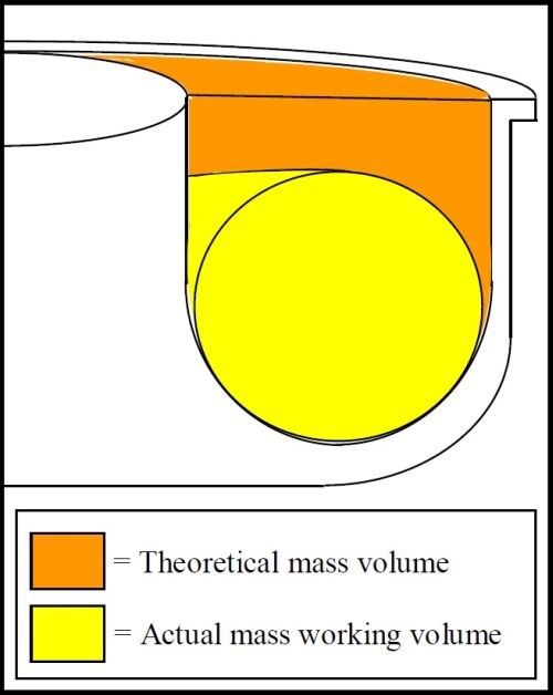
Figure 1 - A cross-sectional view of a vibratory bowl processing channel showing the differences between the theoretical bowl volume and the actual working volume.
Detailed in Table 1 are the differences between the theoretical volumes and actual working volumes of traditionally-sized vibratory bowls.1
Table 1 - Theoretical volumes of traditionally-sized vibratory bowls vs. their actual working volumes.1
|
Theoretical |
Actual |
|
1 |
0.8 |
|
5 |
4.0 |
|
10 |
8.0 |
|
15 |
12.0 |
|
20 |
16.0 |
|
25 |
20.0 |
|
30 |
24.0 |
Determining Vibratory Bowl Volume
The shape of the operating channel in a vibratory bowl is that of a toroid or the shape of a bagel, as shown in Fig. 2.
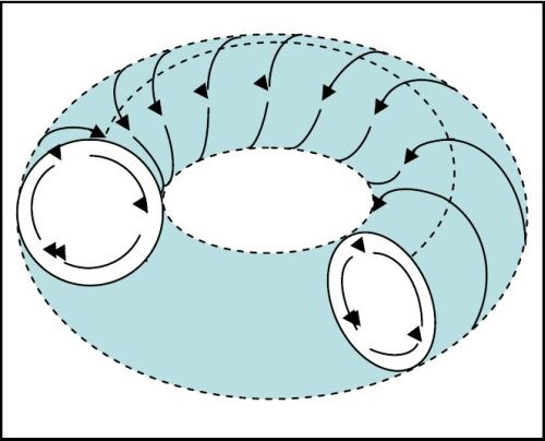
Figure 2 - The toroid-shaped mass and rolling pattern of parts in a traditional vibratory bowl.
Referring to Fig. 3, when the volume of a vibratory bowl is unknown (sometimes used equipment is purchased and the original operating manual has been misplaced), it is possible to calculate the bowl volume, using the volume formula for a toroid as follows:1
Toroid volume = (1)
Where R = distance from OD wall to toroid center
r = distance from ID wall to toroid center
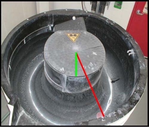
Figure 3 - Typical vibratory bowl on which the toroid formula R and r dimensions have been superimposed. R is the red line, measuring 26.875 inches in this photo; r is the green line, measuring 8.875 inches in this photo.
Using the bowl dimensions in Fig. 3, the volume of this bowl can be calculated using the toroid formula as follows:
1. Volume =
2. = 26.875 in. + 8.875 in. = 35.75 in.
3. = (26.875 in. – 8.875 in.)2 = (18 in.)2 = 324 in.2
4. = (0.25)(3.14)2 = (0.25)(9.86) = 2.47
5. (2.47)(35.75 in.)(324 in.2) = 28,610 in.3
6. 28,610 in.3 ÷ 1,728 in.3/ft.3 = 16.56 ft.3
Calculating Part Volume
The first step in determining the proper loading rate for vibratory bowl finishing operations is to determine the volumetric displacement of the parts to be processed. Therefore the part length, width and height must be accurately measured (Figs. 4 - 6).
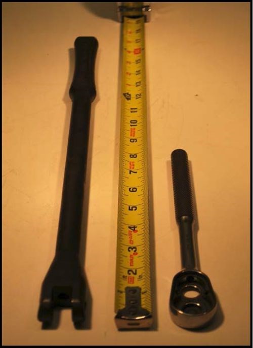
Figure 4 - Two parts being measured for length: 16.5 in. left-side part and 8 in. right-side part.
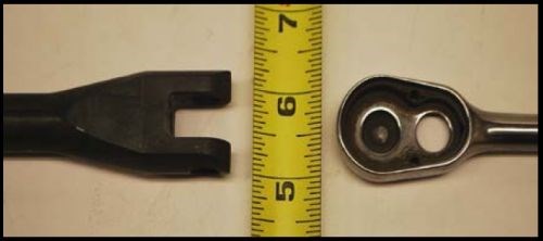
Figure 5 - Same parts being measured for width: 1.125 in. left-side part and 1.125 in. right-side part.
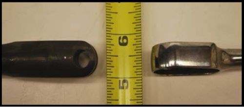
Figure 6 - Same two parts being measured for height: 0.75 in. left-side part and 0.625 in. right-side part.
Once these dimensions have been obtained, it is possible to determine the volumetric displacement of the parts.
For left-side part:
Length = 16.5 in., width = 1.125 in., height = 0.75 in.;
Volume = (16.5 in.)(1.125 in.)(0.75 in.) = 13.92 in.3
For right-side part:
Length = 8.0 in., width = 1.125 in., height = 0.625 in.;
Volume = (8.0 in.)(1.125 in.)(0.625 in.) = 5.63 in.3
Determining Part Loading per Cubic Foot of Volume
The question now remains, how many pieces can be placed into a cubic foot of volume, as the answer to this question will determine the practical loading limitations for the vibratory bowl. Using purely mathematical calculations, this load number can be determined as follows:
One cubic foot volume:
1 ft3 = (12 in.)(12 in.)(12 in.) = 1,728 in.3
For left-side part:
1,728 in.3/ft.3 ÷ 13.92 in.3/pc. = 124 pcs/ft.3
For right-side part:
1,728 in.3/ft.3 ÷ 5.63 in.3/pc. = 307 pcs/ft.3
These simple volumetric calculations can be applied to steel parts which traditionally represent approximately 80% of workloads in vibratory finishing. However not all steel parts can be fit into this loading calculation model. Although they can be processed by vibratory finishing, there are parts that, because of their geometrical shape, metallurgical softness or weight density, have to be processed with additional considerations relative to potential damage that may be occur during their finishing cycle.
Part Dimensional and Weight Considerations and How They Affect Vibratory Loading
Handling long or skinny-shaped parts
Part dimensions and part weight will have an impact on the efficiency with which a vibratory bowl can be loaded. Both part dimensions and weight can affect the rolling pattern possible in the vibratory bowl and the propensity for the part to cause part-on-part damage should it strike other parts during the processing cycle.
Parts that are exceptionally long are problematic in that their length can cause a phenomenon known as log-jamming in the vibratory bowl. This is exceptionally true if the overall length of the part matches the width of the channel, as shown in Fig. 7. Here, the wrench is exactly the perfect length to lodge across the width of the channel resulting in a build-up of media and parts behind the jam and their spill over the brim of the channel. When this occurs, parts can and will jam sideways in the channel to create a dam behind which other parts and media will build up. The result is an overflow of media and parts over the bowl channel brim and onto the shop floor.
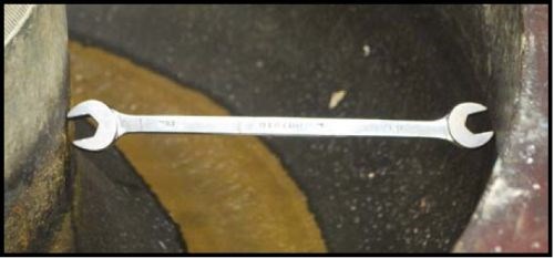
Figure 7 - A wrench jammed into a vibratory bowl channel.
To minimize this from occurring, a long-radius vibratory bowl is typically used when finishing long, skinny parts, as shown in Fig. 8.1 When compared to the traditional style vibratory bowl shown in Fig. 3, the center hub of a long-radius machine has a wider diameter versus the width of the operating channel. The narrow channel physically prevents long-shaped parts from turning sideways and jamming the channel.
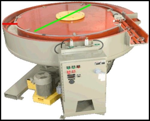
Figure 8 - A long-radius bowl with a wide center hub (green line) versus a narrow channel width (red line).
The helical roll of parts in a long radius bowl is akin to a javelin in flight. Figure 9 shows an overhead view of a 40 ft.3, long-radius style vibratory bowl. The center hub diameter on this bowl is 105 in. It has a channel width of 19 in. The parts being processed in this bowl are 24 in. long. Despite its slight arc, any short-length segment of the operating channel in a long radius vibratory bowl is essentially a short-length section of straight channel, as shown in Fig. 10.1
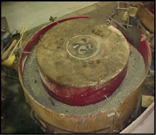
Figure 9 - Overhead view of a 40 ft3, long-radius style vibratory bowl.
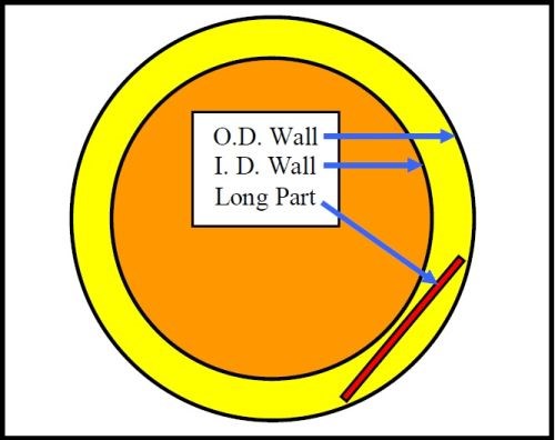
Figure 10 - Overhead view of a long, skinny part in a long-radius bowl channel.
Processing heavy parts
In high-quality decorative finishing applications, parts weighing more than 1 lb. should be processed to avoid part-on-part contact. Lighter weight parts harder than Rc 40 will rarely incur part-on-part damage. Parts; heavier than 10 lb. should be processed in compartmentalized vibratory equipment or processed uniquely to prevent damage, as shown in Fig. 11.
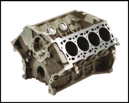
Figure 11 - A cast steel, automotive, V8 engine block weighing approximately 550 lb.
Figures 12 and 13 show a compartmentalized vibratory bowl and tub respectively.1 Both vibratory machines permit multiple part processing in which each part is processed in its own unique compartment. Compartmentalization will ensure 100% total protection against part-on-part damage when either exceptionally heavy, exceptionally delicate, or metallurgically soft parts are being finished.
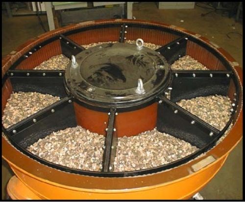
Figure 12 - Overhead view of a compartmentalized vibratory bowl with individual compartments for uniquely heavy or delicate parts; loaded one per compartment.
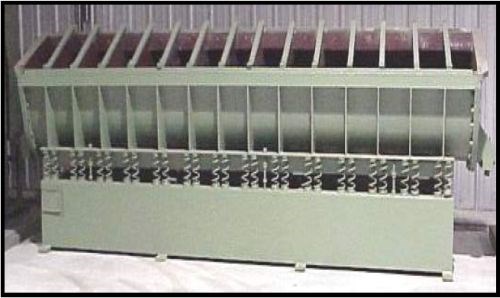
Figure 13 - Compartmentalized vibratory tub that permits multiple part processing, where each part is uniquely processed in its own discrete compartment.
Part orthographic projection
Sometimes when considering vibratory bowl loading, it is important to consider part loading using its orthographic projection. This is exceptionally important when a part is fragile or metallurgically soft. As an illustrative example, Fig. 14 shows a delicate, brass, chandelier trim piece that has been sand-casted and is to be vibratory processed to remove casting flash. The brass trim piece shown is both fragile and metallurgically soft. To avoid part-on-part damage it cannot be processed in high volume. Calculating its true volume and loading rate, as shown earlier, will not represent its practical loading rate because of its delicate nature.

Figure 14 - A delicate, brass, chandelier trim piece that has been sand-casted and is to be vibratory processed to remove casting flash.
When situations like this occur in the vibratory room, the correct way to determine the part loading rate is by calculating its volume using its orthographic projection.1 In an orthographic projection, only the object length is considered as the item’s volume measurement. Using the object length, the part volume is projected as the sphere which would be created if the object were rotated on its X, Y and Z axes, as seen in Fig. 15.
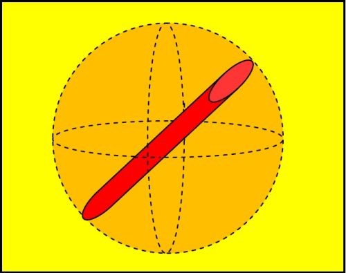
Figure 15 - The orthographic volumetric projection, or sphere that is created, for a long, cylindrical part when the part is rotated on its X, Y and Z axes.
The resulting sphere that is generated during the projection represents the “safe” calculable volume when determining the loading of a delicate part for vibratory processing. The volume of a sphere is given by the following formula:
Sphere volume = (2)
where r = radius of the sphere.
Illustrative calculation:
Let us assume that the long cylinder shown in Fig. 15 is 8 in. in length. This means the radius of the resultant sphere would be 4 in. The orthographic volume for this part would be:
1. (4/3) = 1.33
2. π = 3.14
3. r3 = (4 in.)3 = 64 in.3
4. (1.33)(3.14)(64 in.3) = 267.28 in.3
Knowing that the part occupies an orthographic volume of 267.28 in.3, it is possible to calculate the number of pieces that will occupy 1 ft3 of volume as follows:
5. 1,728 in.3/ft.3 ÷ 267.28 in.3/pc. = 6.47 pcs.
To be safe, the practical loading limit for this part would be 6 pcs./ft.3 of actual vibratory bowl volume.
Part-on-part impingement damage
Without a doubt, the biggest contributor to poor part quality during vibratory finishing is part-on-part impingement damage. Typically, part-on-part damage occurs when the desire to maximize productivity overrides the practical loading limits of the machine based upon part volumetric loading parameters or orthographic loading projections for metallurgically softer metals. The onset of part-on-part impingement damage is additionally exacerbated by the physics of the shape of the toroid and the rolling pattern in the vibratory bowl, as seen in Figs. 16 - 18.
Figure 16 shows a three-quarters view of a vibratory bowl. It is easy to see that the I.D. center hub is a smaller diameter circle than the O.D. wall of a vibratory bowl. As parts roll in the vibratory mass, they move from the O.D. wall toward the center hub. As a result of this rolling action, the parts consequentially get closer together near the smaller diameter center hub.
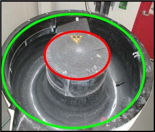
Figure 16 - The center hub of a vibratory bowl (red circle) is a smaller diameter circle that the OD wall of the vibratory bowl (green circle).
Figures 17 and 18 show the differences in two rolling patterns. In Fig. 17, a closed spiral pattern, the parts roll four times per lap around the bowl channel. In Fig. 18, they roll eight times. The coils of the spiral are closer to one another in Fig. 18. We can therefore infer that each discrete, small section of a traditional vibratory bowl channel is actually pie-wedged in shape (Fig. 19).1
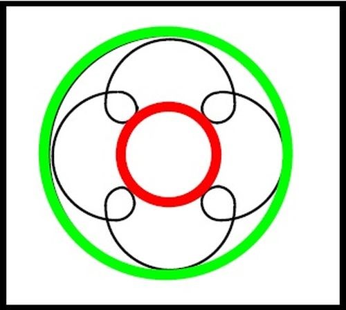
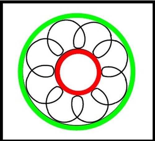
Figure 17 - Open spiral mass rolling pattern. Figure 18 - Closed spiral mass rolling pattern.
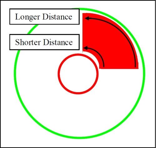
Figure 19 - The pie-wedged channel shape formed by the rolling pattern in Fig. 17.
The pie wedge shown in Fig. 19 consists of one quarter of the toroid volume. The distance from trailing edge-to-leading edge of the pie wedge on the center hub side of the wedge is a shorter distance than the distance on the O.D. side of the wedge. Since parts progress a shorter distance to achieve one quarter of the toroid channel length when they are closer to the center hub, the parts are consequently in closer proximity to one another, fostering the potential of part-on-part contact. This is especially true in heavily loaded vibe bowl situations. Although not shown, the pie wedge for Fig. 18 would be even narrower as the rolling pattern in the figure represents a tighter one-eighth distance of the toroid’s channel volume.
Understanding that this physical constraint results in mechanical complications when loading the machine, the loading of parts must be tempered by the possible adverse consequences relative to machine overloading. Concomitant to this is a general understanding of the metallurgical softness of the parts and the propensity for part-on-part contact to occur.
Suggested loading efficiencies for assorted parts and metals
As noted earlier, certain metals have different metallurgical characteristics. Most important of these relative to vibratory processing is the hardness of the metal (Table 2). As parts roll downward at the center hub of a vibratory bowl, they are under compressive loading from the media mass above. This can result in media impingement on a metallurgically softer metal wherein a piece of media is trapped against the vibratory bowl I.D. wall and the part, in addition to the close part-on-part proximity caused by the pie-wedged shape of that portion of the bowl channel.
Table 2 - Brinell and Rockwell hardness characteristics of typical metals in order of sequential hardness.
|
Metal to be |
Hardness |
Can be |
Maximum |
|
Lead |
Brinnell 1.0 |
No |
0% |
|
Gold |
Brinnell 1.8 |
No |
0% |
|
Babbitt (alloy) |
Brinnell 2.0 |
No |
0% |
|
Silver |
Brinnell 2.4 |
No |
0% |
|
Tin |
Brinnell 2.8 |
No |
0% |
|
Zinc (cast) |
Brinnell 3.0 |
Yes* |
< 5%* |
|
Copper |
Brinnell 12.0 |
Yes* |
< 5%* |
|
Brass |
RB 14 |
Yes* |
5%* |
|
Aluminum |
RB 34 |
Yes |
5% |
|
Bronze |
RB 50 |
Yes |
5% |
|
Cast Iron |
RC 38 |
Yes |
10% |
|
Mild Steel |
RC 40 |
Yes |
20% |
|
Vanadium Steel |
RC 45 |
Yes |
35% |
|
Mild Cr/Ni Stainless |
RC 48 |
Yes |
35% |
|
Hard Cr/Ni Stainless |
RC 52 |
Yes |
50% |
|
Hard Steel |
RC 55 |
Yes |
50% |
|
Carbide Steel |
RC 60 |
Yes |
50% |
|
*Possible but strongly suggested as a poor candidate. |
|||
References
1. W.P. Nebiolo, REM Training Manual Edition No. 8, (April 4, 2012).
2. W.P. Nebiolo, “A Comparison of the Advantages and Disadvantages of Assorted Mass Finishing Techniques,” in Proc. NASF SUR/FIN 2009, NASF, Washington, DC (2009).
RELATED CONTENT
-
Buffing & Polishing: The Need for Speed
The correct peripheral speed is an important consideration in getting the right results from your buffing operation. A buff that is turning too fast or too slow may result in damage to the buff or to the workpiece.
-
Drivers of Change
Is your metal finishing software ready for an upgrade?
-
Achieving a Mirror Finish
New buffing technology minimizes clean-up and improves quality, cycle time and finish on automatic/robotic applications.


