Looking Back - The 24th William Blum Lecture
This article is a re-publication of the 24th William Blum Lecture, presented at the 70th AES Annual Convention in Indianapolis, Indiana, on June 27, 1983. A career retrospective of Mr. Pearlstein’s works, the lecture covered work on electroless plating, chromate conversion coatings, double-layer phenomena and dealing with cyanide wastes.
#surfin
by
Fred Pearlstein
Featured Content
Recipient of the 1982 William Blum
AES Scientific Achievement Award
Editor’s Note: Originally published as Plating & Surface Finishing, 70 (10) 42-16 (1983 and 70 (11), 36-41 (1983), this article is a re-publication of the 24th William Blum Lecture, presented at the 70th AES Annual Convention, SUR/FIN 1983, in Indianapolis, Indiana on June 27, 1983. Originally published in two parts, the lecture was a career retrospective of Mr. Pearlstein’s works. The first part covered work on electroless plating, chromate conversion coatings and double-layer phenomena. The second was devoted to work on dealing with cyanide wastes. A printable PDF version of the complete lecture is available by clicking HERE.
Introduction
I am honored to have been selected as recipient of the AES Scientific Achievement Award and am most pleased to be able to participate in honoring the memory of Dr. William Blum, whom I was privileged to have known quite well; he was indeed a "giant" in advancing the science and technology of electroplating.
I cannot let this opportunity pass without acknowledging that whatever I've been able to accomplish in my career is in large measure owed to my dear wife, Roslyn, for her constant understanding, support and kindness, during the past 27 years. I also wish to thank the AES Philadelphia Branch for the friendships and support and would like to express my gratitude for having had the privilege and pleasure of working with the highly talented AES headquarters staff and society members around the country in association with the AES Education Committee, Intensive Training Course, CEF program, etc.
As the title of this paper implies, I am taking this opportunity to look back over some of my past projects related to plating and surface finishing, not to rehash the old studies, but to focus on some sidelights and highlights of the investigations - some hitherto unpublished in the open literature - that may be of interest.
I can trace my introduction to plating to about 1953 when investigating processes for metallizing plastic dipoles of proximity fuses. I had been intrigued by Brenner's electroless deposition process1 and found that PdCl2 solutions could be used to activate nonconductors for initiating electroless nickel deposition. It seems very mundane now but one of the thrills of my life was observing a piece of white polystyrene initiate gas bubble formation and miraculously become coated with a metallic nickel deposit. Adsorption of a catalytically active species was accomplished by immersion in a warm PdCl2/HCl solution at pH about 4.3, the Tyndall effect indicated presence of a colloid. Unfortunately, this solution had a relatively short useful life, as palladium salt, presumably hydroxide, would soon precipitate out. Certain agents such as gelatin were helpful in temporarily retarding this effect. Immersion in a SnCl2 solution prior to immersion in an acidic PdCl2 bath was a more effective means of activating nonconductors for electroless deposition.2 However, the Shipley colloidal Pd activator3 proved most suitable for commercial use, particularly in the printed circuit industry. Virtually any nonconductor that did not dissolve in the electroless bath could be successfully activated for electroless deposition. An exception was a material identified as "mica-filled phenolic," which resisted all efforts at activation even when visible palladium films were produced on the surface. Apparently, this material contained a potent catalytic poison that prevented successful deposition. Though the phenomenon was not investigated further, it indicated the possibility of preventing deposition where unwanted (e.g., on racks) by incorporating catalytic poisons.
My primary responsibility at that time was the development of a practical process for "electrolytic grinding" of tungsten carbide machine tools. It may be of interest to note that the almost unbelievable current density of more than 450 A/in.2* was obtained at about 6 V, owing to rapid movement of electrolyte and close proximity of tungsten carbide anode and periphery of a rotating copper wheel cathode; a single layer of diamonds bonded to the copper wheel separated the anode and cathode. This work was very interesting and led to a rapid and highly cost-effective process for producing carbide form tools,4 but I was drawn by the mystique of electroless deposition and kept returning to it when I could find an excuse to do so.
Electroless deposition
My work with electroless finishing dealt with nickel alloys, copper alloys, silver, cobalt and palladium, among other metals. The following discussion presents some of the highlights.
Alloy deposits
Electroless plating baths were modified to enable the deposition of ternary and quaternary alloy deposits in order to increase the variety of chemical, physical and mechanical properties that could be utilized for particular applications.5 Autocatalytically deposited alloys such as Ni-W-P and Ni-Re-P are potentially useful for applications where higher temperature or greater chemical resistance is required than can be obtained from conventional Ni-P deposits. Mallory6 has developed numerous interesting and potentially useful polyalloys. I feel that electroless alloy deposits have not yet been fully developed and exploited.
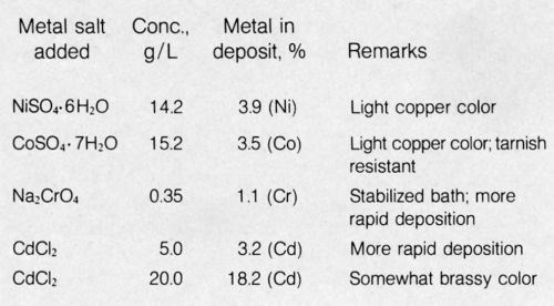
What follows is a summary of some unpublished work on electroless copper alloys using a primitive bath: 69 g/L Rochelle Salt (tetrahydrate) + 20 g/L NaOH + 13.8 g/L CuSO4 + other metal salts. In addition, 40 mL of 36% HCHO (containing 12.5% methanol as preservative) was added per liter of the above bath. See Table 1 for details and remarks.
It is noteworthy that the addition of chromate had a strong stabilizing effect on the bath yet increased the deposition rate significantly. Electroless copper and alloys readily deposited on clean steel, but the presence of chromate in the bath prevented any deposition on steel, probably by passivation; deposition was not inhibited on palladium-activated surfaces. Perhaps this phenomenon could be utilized to achieve selective deposition. The electroless copper-cobalt alloy was strongly adherent to steel, was lighter in color than would have been expected from the cobalt content, and was considerably more tarnish resistant than normal copper deposits. Cadmium is normally considered a catalytic poison in electroless plating baths but exhibited no such characteristics in the electroless copper bath; deposits contained as much as 18.2% cadmium, as shown in Table 1. Additions of a bath stabilizer such as 2-mercaptobenzothiazole (MBT)7 to the electroless copper alloy baths tended to decrease the concentration of the alloying element in deposits, except for cadmium, which was increased. A bath containing 10 g/L CdCl2 and 12 mg/L MBT produced brassy-appearing deposits containing more than 29% Cd. An electroless copper bath based on DMAB reducing agent was developed that produced adherent strike deposits on steel and could be codeposited with 10% tin.8
Table 1 - Electroless copper alloys.
Electroless silver
A bath was developed for electroless silver9 deposition that appears to have found application for coating waveguides of a communications satellite. In order to help elucidate the mechanism of deposition, a divided-cell experiment was conducted.10 This is illustrated diagrammatically in Fig. 1. The work was done after publication of the main studies.
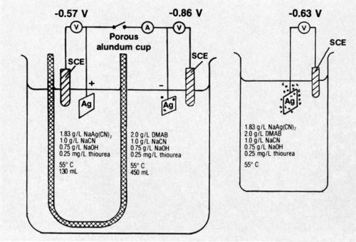
Figure 1 - Diagrammatic representation of divided-cell experiment conducted with electroless silver bath.
The potential of a silver specimen in the solution containing dimethylamine borane (DMAB) but no silver salt was found to be -0.86 V compared to -0.57 V (vs. saturated calomel electrode) for a silver specimen in the solution containing NaAg(CN)2 but no DMAB. Very slight gas evolution was noted on the specimen in solution containing DMAB; there was no visible gassing on the specimen in the other solution.
When the specimens in the divided cell were short circuited through a recording milliammeter, a very evident increase in gas evolution on the specimen in the DMAB-containing solution resulted. No gassing was produced on the specimen in the DMAB-free solution. The current flow between specimens in the divided cell was 4.0 mA initially, increased to a maximum after 35 min and, at the end of the 60-min test, was 4.5 mA. The total coulombs passed was 17.46, determined by graphical integration of the chronopotentiometric curve. The single electrode potentials of the short-circuited specimens were -0.71 (silver-free solution) and -0.64 (DMAB-free solution); the potential difference represents the IR drop through the solutions.
The steady-state mixed potential of a silver specimen autocatalytically plating from a bath containing all constituents was about -0.63 V; vigorous gas evolution was evident during plating. Hydrogen gas evolution is typically associated with deposition by the autocatalytic chemical reduction mechanism. Gassing on the electrode of the short-circuited divided cell was markedly less vigorous that that of the specimen autocatalytically plating in the complete bath.
The specimens used in the divided-cell experiment were weighed after they had been externally short circuited for 60 min. The specimen in the solution containing DMAB (no silver salt) was unchanged in weight (actually 0.1 mg weight loss). The other specimen had gained 16.3 mg of silver deposit. From the coulombic input, a deposit weight of 19.5 mg would have been expected, thus indicating that deposition was obtained at about 84% cathode current efficiency. The balance of the current presumably had been consumed by the formation of hydrogen. However, gas bubble formation was not evident during plating of the specimen so it is assumed that the rate of hydrogen gas formation (calculated at 3 × 10⁻⁵ g/hr) was sufficiently slow to have escaped visual detection. The specimen plated for 60 min in the total preferred bath at 55°C gained 33.3 mg or more than double that of the plating specimen of the divided cell. The difference in the deposition rate is believed attributable to the additional solution resistance that had to be overcome as a result of the divided-cell configuration.
It is interesting to note that when a platinum specimen was substituted for silver in the NaAg(CN)2-free solution of the divided cell, significant current flow was not produced by short circuiting and there was no silver deposition on the silver specimen in the DMAB-free solution. When the specimen positions were reversed, current flow was generated as previously and the platinum in the DMAB-free solution was plated with silver. The catalytic nature of the plating process was thus demonstrated; solid platinum is evidently not catalytically active for oxidation of DMAB. A platinum specimen immersed in the complete preferred bath for 60 min at 55°C did not initiate autocatalytic silver deposition.
The half-cell reactions are probably best represented by the following:
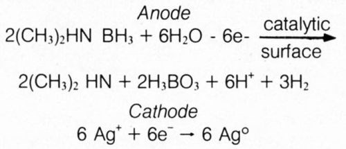
These results appear to substantiate the hydride mechanism of electroless deposition using DMAB, as had been advocated by Lukes for autocatalytic deposition from formaldehyde- and hypophosphite-based baths.11 Hydrogen gas, normally encountered by electroplaters at the cathode, was produced as part of the anodic reaction in the divided-cell experiment. This is explained by hypothesizing an initial step of transfer of a hydride ion (H+) from DMAB to the catalytic surface. However, the anodic half-cell reaction cannot take place at a significant rate (evidenced by lack of significant hydrogen gas evolution) as there are no readily reducible species available for reaction with electrons from hydride ions. When an external electrical connection is made to the metal in the solution containing the readily reducible silver ions, the electron is released from the hydride ion to travel to the interface of less-negative potential, where a silver ion is reduced; the atomic hydrogen left on the anodic member can then combine to form molecular hydrogen gas: 2H+ + 2e– ⇒ H2.
Electroless cobalt
Brenner showed that although electroless deposition of cobalt or nickel is accomplished from similar alkaline hypophosphite baths, only nickel is deposited from acid baths.12 Years later, an acid cobalt bath was successfully developed based upon DMAB reducing agent.13 The effect of hypophosphite addition to this bath on the deposition rate and potential was determined in an attempt to gain some insight into the reason for failure of hypophosphite to enable electroless deposition of cobalt from acid baths. The results are shown in Fig. 2. The parallel between steady-state mixed potential of the depositing metal and plating rate is striking, and even relatively small concentrations of hypophosphite prevented deposition from the DMAB bath. The presence of hypophosphite in the bath may be analogous to lowering the hydrogen overvoltage of the surface and thus preventing attainment of a sufficiently negative potential for cobalt deposition to occur; a potential of about -0.67 V is required for cobalt to be deposited from this bath, whereas only about -0.59 V is required for nickel deposition.
Electroless cobalt deposits have been used primarily for their magnetic properties.14 Perhaps overlooked is the potential use of cobalt deposits for corrosion prevention. The acid cobalt deposits on steel were found superior in some respects to electroless nickel for corrosion prevention. The cobalt is more galvanically compatible with steel and provided more effective protection at sharp edges and at faying surfaces when plating of assemblies was required. The cobalt itself will tarnish unless chromate treated, e.g., by immersion for 10 sec in 200 g/L Na2Cr2O7•2H2O + 6 mL/L H2SO4, and rinsed. An electroless deposit, truly sacrificially protective to steel, may be within reach by development of a bath for deposition of a cobalt-zinc alloy, for example.
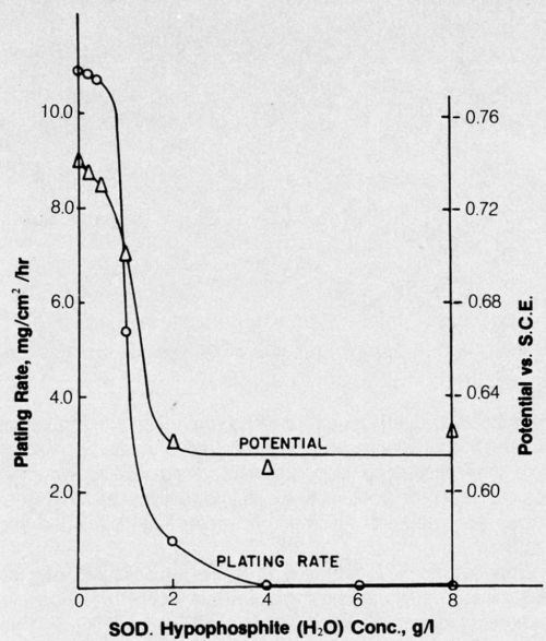
Figure 2 - Effect of hypophosphite additions on electroless cobalt plating rate and potential. Bath was operated at pH 5.0 and 70°C and contained 25 g/L cobalt sulfate (CoSO4•7H2O) + 25 g/L succinic acid (C4H4Na2O4•6H2O) + 15 g/L sodium sulfate (Na2SO4) + 4 g/L DMAB.
Electroless palladium
There is renewed interest in palladium deposits for electronic applications at the present time but no attention appears to have been directed to the use of electroless plating for this purpose. A hypophosphite-based bath15 was capable of deposition at about 2.5 μm/hr and, though studied only in the laboratory, should, with a little additional work, be capable of commercial exploitation. It was also noted that the electroless palladium deposits can be increased in hardness and wear resistance by adding small amounts of nickel or cobalt salt to the bath. In addition, incorporation of alloying constituents may moderate the catalytic activity that has limited the use of palladium for some electronic contacts, since the metal can catalyze polymerization of organic components of the atmosphere to form resistive films. Other electroless palladium plating baths were developed by Rhoda16 and Sergienko.17 I believe that electroless palladium should be explored for some applications where electrodeposited palladium is currently being considered.
Chromate conversion coatings
The application of chromate conversion coatings to zinc, aluminum, magnesium, copper alloys, cadmium, tin, silver, etc., for improved corrosion resistance, a base for paint and for producing a range of decorative colors, including black, is well known. Heating of chromate-coated zinc or aluminum at 100°C or more essentially nullifies the corrosion resistance of the film by insolubilizing inhibitive hexavalent chromium compounds and by film cracking.18 It may be worth adding that when the chromated metal was heated in a steam autoclave at well over 100°C, insolubilization of the hexavalent chromium did not occur and corrosion resistance was not adversely affected. Based upon this observation, it was considered that a film of glycerine on freshly formed chromate film applied by a final rinse in 10% by volume glycerine in water might prevent the apparent dehydration effects. Whatever the mechanism, glycerine treatment proved promising, particularly on chromated aluminum, for retention of corrosion resistance even when heated 2 hr at up to 200°C.19 Chromated aluminum alloy 2024-T3 was effectively protected for more than 2 years' exposure to direct sunlight at tropical marine sites; bare aluminum was catastrophically corroded.20 For those who may be concerned, anodized aluminum that has been dichromate sealed is not adversely affected in corrosion resistance or leachability of hexavalent chromium compounds by heating at up to 200°C, though some crazing of the anodic coating results.
For all the benefits derived from chromate films, there are, of course, limitations, and one often overlooked is the increase in coefficient of friction. However, this can be overcome easily by applying a thin oil or wax film.
Chromate films are applied to beryllium to help prevent corrosion at salt environments. A bath was developed for this purpose,21 though others used for chromating aluminum may also be applicable. The chromate film on beryllium also had the unexpected remarkable capability to prevent high-temperature oxidation.22 Further studies showed that oxidation was primarily the result of combining with moisture in the air; the rate of oxidation was very much slower in dry air. In fact, oxidation in moist nitrogen (saturated with H2O at 22°C) was as rapid as oxidation in moist air (Fig. 3). The chromate film apparently interferes with the surface reactivity of beryllium and water vapor. The retarding effect of chromate is shown in Fig. 3. Incidentally, some anodic coatings on beryllium23 are also effective for preventing high-temperature oxidation.
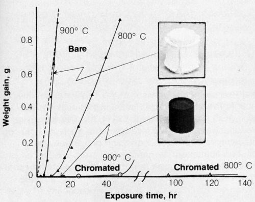
Figure 3 - Oxidation of hot-pressed beryllium, bare or chromated, in moist air at 800 and 900°C. (Dotted line indicates oxidation of bare beryllium in moist nitrogen at 900°C.
Double layers
Double-layer nickel deposits consisting of an initial layer of leveling semibright nickel plus a bright nickel topcoat have found widespread use for eliminating mechanical polishing and for the synergistic corrosion resistance obtained.24 It is generally accepted that enhanced corrosion resistance arises from the galvanic relationship between the two layers; the outer layer containing sulfide from the brightening agent is more active (more negative corrosion potential) than the underlying relatively pure nickel and prevents corrosion penetration of the initial barrier layer by a sacrificial protection mechanism.
Single- and double-layer nickel coatings on steel were exposed at tropical environments.25 The superiority of the double-layer deposits was confirmed at a marine and near-marine site; a 20-μm total double-layer thickness was more protective than a 40-μm single layer. There was no clear superiority exhibited at a humid, rain forest site. The results indicated that for long-term effective protection the initial layer should be about 30 μm in thickness with a 10-μm bright nickel topcoat; 15-μm layers with a 5-μm topcoat generally were inadequate.
Studies, the results of which were recently reported,26 had been conducted on double-layer electroless deposits. Double-layer deposits comprised of conventional electroless nickel followed by a deposit of (1) electroless nickel (lower phosphorus) from an alkaline bath, (2) electroless cobalt, or (3) electroless cobalt-nickel were shown to provide outstanding corrosion resistance with relatively thin deposits.
I had given consideration to producing double-layer deposits from a single plating bath simply by forming the layers at two different cathode current densities (CCD). Exploratory work was conducted with a tin-zinc alloy plating bath; an initial deposit at low CCD followed by a topcoat at high CCD produced layers differing in alloy composition and some improvement in corrosion resistance was observed over single layers of the same total thickness. Further investigation in this area is suggested. Double layers formed from conventional single-metal plating baths may be advantageous in terms of corrosion prevention and additionally may effect some "dummying" of impurities during deposition at the lower CCD. It would normally be expected that the more active outer layer would be produced at the higher CCD but not necessarily so. It would be nice if an equivalent conventional double-layer nickel deposit could be produced from a single bath by varying the current density.
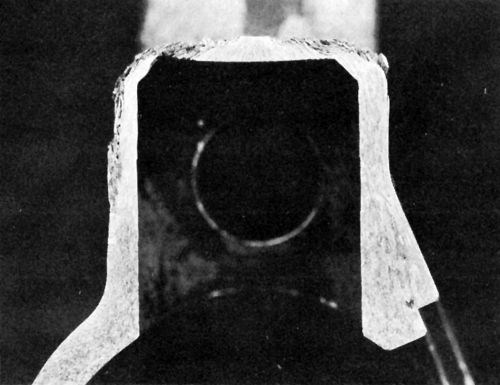
Figure 4 - Cross-section of anodic hard-coated 7075-T6 component after several years’ service in humid environment and contact with perspiration.
A brief study was made of a suggested27 double-layer anodic coating on high-strength aluminum alloy applied initially in sulfuric acid, followed, without removal from the rack, of course, by anodizing in chromic acid. Thin deposits had excellent corrosion resistance but the process was not pursued further until years later when it became important to improve the corrosion resistance of components for military equipment using an anodic hardcoating on 7075-T6, which is susceptible to exfoliation corrosion. Figure 4 is a cross section of a component showing exfoliation corrosion resulting from service in a humid environment and contact with the user's perspiration. Results of studies reflected in Fig. 5 indicated that the incorporation of dichromate in the anodic coating can play an important role in retarding exfoliation corrosion. A double-layer finish consisting of a 5-μm outer coating formed in sulfuric acid at 22°C and a 25-μm inner anodic hardcoating at 0°C proved very effective in providing resistance to both wear and exfoliation corrosion (as indicated in Fig. 5d), the latter owing to greater adsorption of dichromate in the outer layer. (Note: The outer coating is formed first because anodic oxide films form at the barrier layer adjacent to the metal.) However, it turned out unnecessary to utilize the double-layer coating when it was found that abrasive blasting of the aluminum prior to anodic hard-coating resulted in greatly increased adsorption of dichromate and resistance to exfoliation corrosion (Fig. 5e). A single, multipurpose anodizing electrolyte28 can produce a conventional anodic coating or an anodic hard-coating simply by changing the anodic current density. It is therefore possible to obtain a double-layer anodic coating from a single bath where this might be advantageous for a particular application.
Double sealing of conventional anodic coatings was shown capable of providing synergistic corrosion resistance.29 For example, it was found that sealing anodic coatings on highly corrodible 2024-T3, first in a nickel acetate bath, then in a dichromate seal, provided exceptional corrosion resistance during exposure for many years at a severe tropical marine environment.20
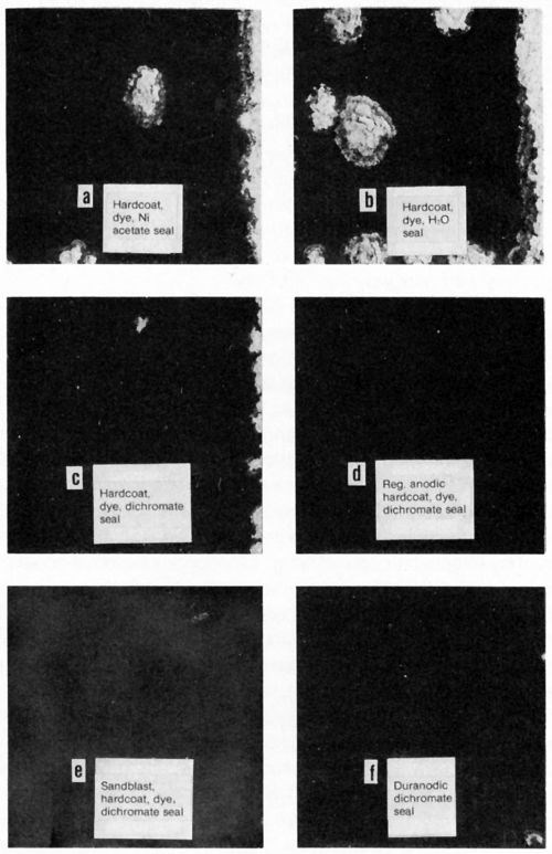
Figure 5 - Aluminum 7075-T6 panels after 56 cycles of the Alcoa spray exfoliation test. Anodic coatings were 30 μm, except for Duranodic (integral color) coating of 23 μm. Upper right edge of each panel was bared of anodic coating prior to test. Black dyeing was followed by 15-sec nickel acetate seal for panels b, c, d and e.
Electrolytic decomposition of cyanide wastes
Cyanide wastes generated by plating shops are usually treated with chlorine or hypochlorite but attention has also been given to the use of peroxides, ozone and electrolysis. The electrolytic process is particularly well suited for adoption by plating facilities without the necessity for additional large capital investment or involvement in unfamiliar disciplines. Moreover, metal salts present in the waste solutions could simultaneously be deposited, perhaps in a readily salvageable form.
The technical literature abounds with reports of electrolysis for decomposition of cyanides, some citing the benefits of adding chlorides, but details that would enable one to assess the effectiveness of the process and select operating parameters for most economically and effectively decomposing cyanide wastes are generally lacking. A systematic investigation of the electrolytic process, the results of which follow, was undertaken by the author.30
Initial studies were conducted on 500-mL samples of simulated cyanide rinse solutions containing 1 g/L NaCN + 0.8 g/L NaOH but without the complicating factor of the presence of metal ions. A pure platinum panel (25 cm2 total area) was centrally located in the beaker. Opposite each face of the anode was a cathode (AISI Type 316 stainless steel) positioned so that one of its faces was adjacent to the interior wall of the beaker and the opposite face (12 cm2) was 3.5 cm from the anode.
Electrolysis tests were conducted with mild agitation (150 rpm of a standard 1-in. Teflon stirring bar) at constant current until a total of 2500 coulombs had passed through the cell. The free (titratable) cyanide content of the bath was then determined by titration with AgNO3 to an iodide endpoint.
Anode current density and chloride concentration
The effect of average anode current density (ACD) and NaCl concentration on the electrolytic decomposition of cyanide was determined (Fig. 6). The ordinate represents the%age of the 0.50 g NaCN (500 mL of 1 g/L) originally present in the test solution that was decomposed by electrolysis.
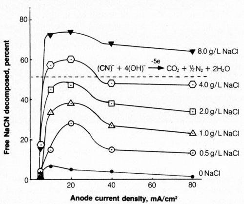
Figure 6 - Effect of anode current density and NaCl concentration on decomposition of free cyanide. Bath was operated at 25°C using 2500 coulombs of electricity and mild agitation (150 rpm) and contained 500 mL of 1.0 g/L NaCN + 0.8 g/L NaOH.
When sodium chloride was not present in the bath, little cyanide decomposition resulted during electrolysis. Adding as little as 0.5 g/L NaCl had a marked effect in increasing the electrolytic decomposition of cyanide; the amount of cyanide decomposed at a given current density increased with increasing chloride content of the bath. At a given chloride concentration the greatest decomposition usually occurred at an anodic current density of 20 mA/cm2 (2 A/dm2; 19 A/ft2). The current density, of course, is not uniform over the platinum and can be expected to be higher at the edges and lower in the center. Evolution of gas at the anode surface appeared uniform and was not visibly more vigorous at the edges, as would be expected if the current density at the edges were very much greater than that near the center.
An increase in sodium chloride concentration significantly decreased the solution resistivity and thus reduced the electrical energy requirements at a given current density. The minimum cost of cyanide decomposition, considering the costs of NaCl and electricity, would be expected from solutions containing about 4 g/L NaCl at current densities of 10 to 20 mA/cm2. The latter current density is preferable because of greater decomposition rates, though at perhaps slightly higher costs. At lower current densities, the electrical energy requirements are reduced but the lower efficiency of electrolytic decomposition (Fig. 6) results in higher costs. At values of 40 mA/cm2 or above, the efficiency of free-cyanide decomposition decreased and electrical energy requirements increased.
The specific reaction pathway leading to the decomposition of free cyanide at the anode has not been established. However, it is likely that in the presence of dissolved chlorides, chlorine is liberated at the platinum anode and subsequently reacts chemically with alkali to form hypochlorite, which is well known for its capability to decompose cyanide. A possible reaction path for the cyanide decomposition is given by the following equations:
2Cl– - 2e– ⇒ Cl2 (1)
Cl2 + 2OH– ⇒ ClO– +H2O + Cl– (2)
ClO– + CN– ⇒ CNO– + Cl– (3)
Chloride would thus be regenerated. In addition, CNO– can be further oxidized as follows:
2CNO– + 3ClO– + H2O ⇒ 2CO2 + N2 + 3Cl– + 2OH– (4)
However, it is evident from some of the experimental results that all of the CN had not been completely decomposed to CO2 and N2 (five-electron change); Faraday's Law would have precluded decomposition of more than about 0.255 g NaCN or 51% of the cyanide present (see dashed line in Fig. 6). It is thus evident that a significant portion of the cyanide decomposed to an intermediate stage (undoubtedly the cyanate), which requires only a two-electron change, and thus the results are not inconsistent with Faraday's Law. The direct anodic oxidation of cyanide:
CN– + 2OH– - 2e– ⇒ CNO– + H2O (5)
or the reaction of cyanide with anodically evolved oxygen is comparatively inefficient as shown by the lower% decomposition from solution without chloride (Fig. 6).
Absence of cyanide in solution
A cyanide-free solution was electrolyzed in order to ascertain the amount of hypochlorite or other long-lived cyanide-oxidizing species that can be generated during the passage of a given amount of electric current. Solutions containing 500 mL of 0.8 g/L NaOH + 4 g/L NaCl were electrolyzed at 20 mA/cm2 for various times, after which a solution containing 0.5 g NaCN was introduced with agitation and the% cyanide decomposed by the oxidizing species formed by electrolysis was determined. The results are given in Table 2.
Table 2 - Electrolysis of cyanide-free solution.
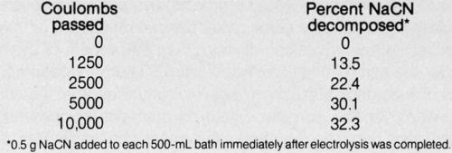
It was previously shown that when 2500 coulombs was passed under the same conditions but with the cyanide present in the bath during electrolysis, 60% of the cyanide decomposed, whereas under the conditions cited in Table 1, only 22.4% of the cyanide decomposed. Part of the explanation for the decreased decomposition when cyanide-free solution is electrolyzed may be cathodic reduction of the oxidizing species when cyanide is not present to consume them. Steady-state concentration of oxidant (apparently hypochlorite) appears to have been approached after passage of approximately 5000 coulombs with the rate of anodic formation of the active species equal to the cathodic reduction rate. It is also possible that chlorine or some other volatile oxidizing species, which could otherwise oxidize cyanide when present in the bath, leaves the cyanide-free solution. Obviously, direct electrochemical oxidation by electron transfer cannot occur during electrolysis of a cyanide-free solution.
Current manipulation
It was thought likely that periodic interruption of current might provide more effective decomposition of cyanide solution because anodically formed oxidizing agents would be allowed more time for chemical reaction with cyanide and thus reduce the possibility of their being discharged at the cathode. When the current was on for 5 sec and off for 15 sec, only 45% of the cyanide in solution (500 mL of 1 g/L NaCN + 0.8 g/L NaOH + 4 g/L NaCl) was decomposed compared to about 60% with continuous current and the passage of the same number of coulombs (2500). When current was on for 15 sec and off 45 sec, about 52% decomposition resulted. It is thus apparent that current interruption is counterproductive to the efficiency of cyanide decomposition. However, rapid fluctuations of current, such as those produced using 48% ripple DC, had no effect on the decomposition rate compared to low (5%) ripple DC. The behavior during interrupted current flow remains unexplained at this time but further studies in this area could help elucidate the decomposition mechanisms.
Bath additives
The effect of halide ion additions on cyanide decomposition was determined and is shown in Fig. 7. It can be seen that fluoride additions were ineffective in promoting cyanide decomposition. The addition of iodide yielded cyanide decomposition results similar to those from chloride additions. Bromide was the most effective of the halide ions in promoting cyanide decomposition; sodium bromide at the same molar concentration as 4 g/L NaCl resulted in decomposition of more than 86% of cyanide under the same conditions that yielded 60% decomposition with chloride additions. However, it is unlikely that the use of bromides for this purpose would be practical for commercial operations because the cost of this salt is considerably greater than that of sodium chloride. Bromide would be worthy of practical consideration if the solutions were recycled as rinsewater after cyanide decomposition was completed.
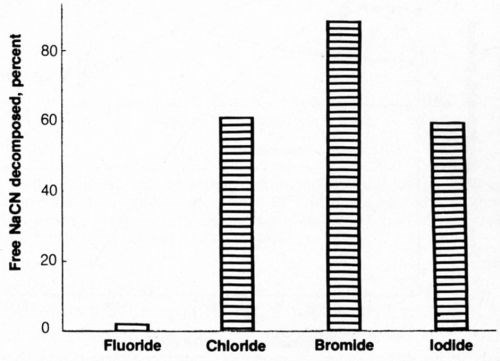
Figure 7 - Electrolytic decomposition of free cyanide in presence of halide ions. Bath was operated at 25°C using 2500 coulombs of electricity and mild agitation (150 rpm) and contained 500 ML of 1.0 g/L NaCN + 0.8 g/L NaOH + halide ion equivalent in molar concentration to 4 g/L NaCl.
The presence of a foam blanket over the solution during electrolysis would be beneficial for reducing the tendency for solution mists to be generated as the result of gas bubbles breaking at the liquid surface. It is also possible that such a foam blanket could retard the escape of gaseous anodic products and enable more complete reaction with cyanide. A nonionic surfactant** at a concentration of 0.5 g/L was added to the solution (1 g/L NaCN + 0.8 g/L NaOH + 4 g/L NaCl) and electrolysis was conducted at 20 mA/cm2. A 0.75-cm foam blanket quickly developed but the decomposition of cyanide was slightly retarded; 56% of the cyanide decomposed instead of the expected 60%, but it would probably be desirable to provide a foam blanket in any production process developed.
A 3.5-g addition of activated carbon was made to 500 mL of the test solution and suspended by mild agitation of the rotating magnetic bar. The solution was electrolyzed while the suspended carbon particles could provide a multitude of tiny bipolar electrodes. After 2500 coulombs had passed, cell voltage and the results of electrolysis were virtually identical in all respects to those of the solution that did not contain the carbon particles.
Thiourea is well known for its capability to adsorb on surfaces and thus affect electrode reactions. However, it was found that additions of 10 or 100 mg/L had little effect on electrolytic decomposition of cyanide; a slight reduction in decomposition effectiveness resulted.
Electrode materials
It is conceivable for cyanide to be cathodically reduced to form products such as CH4, NH3 or CH3NH2 along with anodic oxidation during electrolysis. The use of high-hydrogen overvoltage cathode materials should indicate the feasibility of this approach. However, it was found that use of zinc or lead (high-overvoltage materials), or platinum (low-overvoltage material) cathodes did not result in cyanide decomposition rates significantly different from those obtained when stainless-steel cathodes were used. Also, increasing substantially the cathode current density on stainless steel by reducing the cathode area had little effect on the rate of cyanide decomposition. Thus, the cathodic materials and cathodic reactions appeared to play a minor role, if any, in cyanide decomposition. Stainless steel appears to be a very suitable and practical cathode material. It may be advisable to utilize the largest practicable cathode area for any production process in order to minimize cathodic polarization and to reduce the total electrical energy requirements for cyanide decomposition.
A limited number of anode materials may be used for electrolytic decomposition of cyanide because most common metals are attacked in the chloride-containing electrolyte. Platinum, platinized-titanium or platinized-tantalum were found equally effective. Pure palladium was found to be dimensionally stable during electrolysis in cyanide test solutions but was much less effective than platinum for decomposing cyanide. Under the same conditions, less than half the cyanide was decomposed at a palladium than at a platinum anode. The difference in results can be attributed to the lower oxygen overvoltage characteristics of palladium.
Preliminary work was conducted using a titanium panel with a beta lead-dioxide coating formed by anodic treatment in acidified Pb(NO3)2 solution. The coated titanium was used in lieu of platinum for electrolysis of simulated cyanide rinse solution at 20 mA/cm2; the degree of cyanide decomposition was the same as that produced using a platinum anode. Additional work in this area is suggested. Use of ruthenium-oxide-coated titanium was also considered but the project was terminated before this could be explored.
Carbon anodes were also found effective for cyanide decomposition. They are much less expensive than platinized electrodes but suffer from a tendency to disintegrate during use.
Agitation
The effect of agitation on cyanide decomposition at several anode current densities is shown in Fig. 8. Mild agitation (150 rpm), as used in previous tests, proved to be more effective than zero or vigorous (650 rpm) agitation for decomposition of cyanide at 20 mA/cm2. At 40 mA/cm2, the rate of cyanide decomposition increased with an increasing degree of agitation. Operation at 40 mA/cm2, along with a high degree of agitation, may be highly desirable because the rate of deposition would be double that at 20 mA/cm2 with only a modest increase in cost, owing to higher applied voltage. However, the most marked effect was the great decrease in cyanide decomposition at 10 mA/cm2 when vigorous agitation was applied.
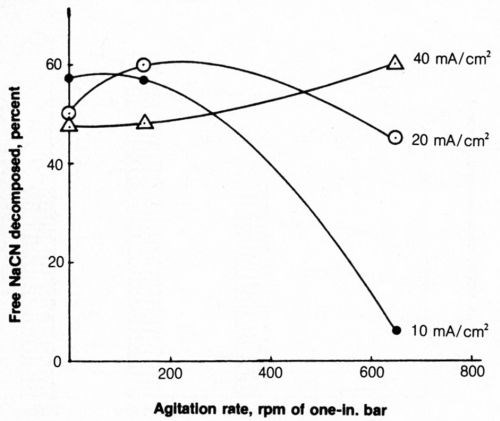
Figure 8 - Effect of agitation on free-cyanide decomposition at several anode current densities. Bath was operated at 25°C using 2500 coulombs and contained 500 mL of 1.0 g/L NaCN + 0.8 g/L NaOH + 4 g/L NaCl.
Solution temperature
The effect of solution temperature on cyanide decomposition at 10, 20 and 40 mA/cm2 is shown in Fig. 9. At 20 and 40 mA/cm2, increasing the bath temperature from 10 to 40°C resulted in an increase of free (titratable) cyanide decomposition; the reverse was true at 10 mA/cm2 with a drastic reduction at 40°C. This was not altogether unexpected in light of the results with vigorous agitation because an increase in temperature which qualitatively can have the same effect as increased agitation, reduces solution viscosity and increases mass transport by diffusion and convection. An increase in solution temperature decreases energy requirements by increasing solution conductivity, but this benefit would probably be offset by the energy required to heat the solution.
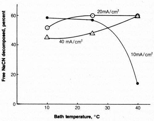
Figure 9 - Effect of bath temperature on free-cyanide decomposition at several anode current densities. Bath was operated with 2500 coulombs and mild agitation (150 rpm) and contained 500 mL of 1.0 g/L NaCN + 0.8 g/L NaOH + 4 g/L NaCl.
Cyanide and hydroxide concentrations
The electrolytic decomposition of free cyanide from 500-mL solutions of various cyanide (and hydroxide) concentrations was determined at a constant coulombic input per unit weight of cyanide present (5000 coulombs/g NaCN). Four g/L sodium chloride was added to each bath. The percentage of the free cyanide decomposed electrolytically was plotted as a function of original cyanide concentration (Fig. 10). It appears from the figure (solid line) that the solution (1 g/L NaCN + 0.8 g/L NaOH) initially selected for these studies as representative of waste rinse solutions was most efficiently decomposed. Higher or lower concentrations of the solution (at a constant NaCN:NaOH ratio) resulted in a decrease in free-cyanide decomposition. The lower concentrations of cyanide-hydroxide solution not only resulted in less efficient electrolytic decomposition of cyanide but the voltage requirements increased because of higher solution resistivity.
When the NaCN concentration was constant at 1 g/L, an increase in the sodium hydroxide content of the bath resulted in reduced efficiency of cyanide decomposition; when the NaOH concentration was constant at 0.8 g/L, an increase in NaCN concentration increased decomposition efficiency. An increasing concentration of alkali is assumed to increase the tendency for oxygen evolution, which competes with the reaction involving chloride. It is evident that electrolytic decomposition of cyanide from highly alkaline solutions is quite inefficient. Perhaps the efficiency of these solutions would be markedly improved if the chloride content were correspondingly increased.
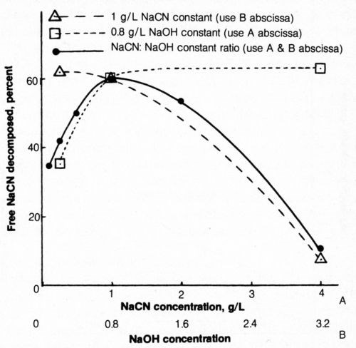
Figure 10 - Effect of NaCN and NaOH concentration on free-cyanide decomposition. Bath was operated at 25°C using mild agitation (150 rpm) and 5000 coulombs per gram NaCN originally in solution at 20 mA/cm2; each 500-mL solution contained 4 g/L NaCl.
Electrolysis time
The effect of total coulomb flow at 20 mA/cm2 through 500 mL of solution on the concentration of cyanide and cyanate is shown in Fig. 11. The cyanide content decreased - as determined by specific-ion electrode measurements - with increasing coulomb flow (electrolysis time) from 1 g/L to less than 0.0001 g/L NaCN after 7500 coulombs; titration measurements were of little value at such low cyanide levels. Thus, virtually complete elimination of free (titratable) cyanide was accomplished by passing 7500 coulombs through the bath. However, the cyanate content of the bath, determined by a colorimetric method,31 increased with electrolysis time to a maximum at about 5000 coulombs flow and did not reach low values (i.e., 12 mg/L) until about 10,000 coulombs had flowed. A distinct odor of hypochlorite persisted in the solution through which 10,000 coulombs had passed. It should be noted that cyanate is considered much less toxic than cyanide and is readily decomposed by acid hydrolysis at about pH 3.
The cost of complete decomposition of NaCN under the conditions cited above can be calculated as follows (the applied voltage over the run was 6.4 to 7.4.):
Cost in C/kg NaCN decomposed = 38.3 × cost in ¢/kW-hr + 8.8 × cost in ¢/lb NaCl
It is evident that the cost of electrical energy exceeds the cost of NaCl; it may therefore be economically sound to increase the NaCl content from 4 to perhaps 8 g/L for greater efficiency of electrolytic decomposition and increased bath conductivity. It is interesting to note that the solution pH decreased with time from 12.0 to 10.3 and the decrease was particularly rapid toward the end of the run.
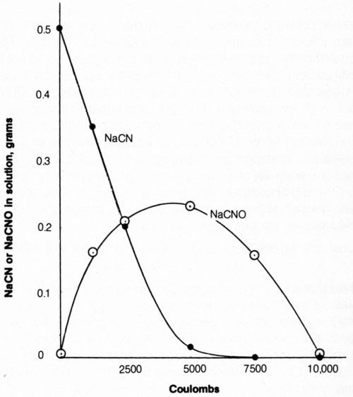
Figure 11 - Effect of quantity of electrolytic current on free cyanide and cyanate content of solution. Bath was operated at 25°C with mild agitation (150 rpm) and an anode current density of 20 mA/cm2. The 500-mL solution contained 1.0 g/L NaCN + 0.8 g/L NaOH + 4 g/L NaCl.
Metal salt additions
The addition of approximately 0.16 g copper or zinc per liter of test solution (1 g/L NaCN + 0.8 g/L NaOH) was made with the appropriate addition of Cu2O or ZnO. Both cyanide decomposition and metal deposition were determined. The effect of NaCl concentration is shown in Fig. 12.
The amount of metal (copper or zinc) deposited after the passage of 2500 coulombs of electricity at 20 mA/cm2 increased with increasing chloride content up to 4 g/L NaCl and decreased slightly at 8 g/L NaCl.
Increasing chloride in the bath containing zinc compounds increased the effectiveness of electrolytic decomposition of cyanide (as with baths free of zinc), though at slightly lower efficiency in baths containing 4 and 8 g/L NaCl.
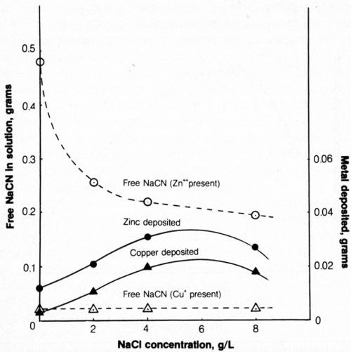
Figure 12 - Effect of chloride content of solution on metal deposition and free-cyanide content after electrolysis. Bath was operated at 25°C using 2500 coulombs and mild agitation (150 rpm) and contained 500 mL of 1 g/L NaCN + 0.8 g/L NaOH + 0.298 g/L Zn+2 or 0.334 g/L Cu+; the anode current density was 20 mA/cm2.
In the presence of copper ions, only cyanide that is not part of the Na2Cu(CN)3 complex is titratable as free cyanide; the free cyanide in the test solution amounted to 0.268 g/L NaCN or the 500-mL bath contained 0.134 g free NaCN. Electrolysis of the baths containing copper and varying amounts of chloride resulted in a decrease of free cyanide to a constant level of about 0.036 g/L (0.018 g/500 mL). The result with baths free from chloride was unexpected because electrolysis of chloride-free/ copper-free baths resulted in the decomposition of only about 0.03 g NaCN while in the copper-containing bath, about 0.116 g NaCN was decomposed. It is therefore evident that the presence of copper exerts a catalytic influence on cyanide decomposition and there appears to be no benefit to adding chloride, except, as indicated above, that copper deposition is enhanced.
The effect of CCD on metal deposition and cyanide decomposition is shown in Fig. 13. The weight of zinc deposited after a flow of 2500 coulombs was greatest at 20 mA/cm2 while the weight of copper deposited was greatest at 10 mA/cm2 and would probably be even greater at lower CCD.
The cyanide content of the solution containing zinc was lower after electrolysis at 20 mA/cm2 than at higher or lower CCD as had previously been found for metal-free cyanide solutions. The cyanide content of baths containing copper was reduced to a constant level of 0.018 g (0.036 g/L).
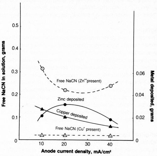
Figure 13 - Effect of current density on metal deposition and cyanide content after electrolysis. Bath was operated at 25°C using 2500 coulombs and mild agitation (150 rpm). The 500-mL solution contained 1.0 g/L NaCN + 0.8 g/L NaOH + 4 g/L NaCl + 0.298 g/L Zn+2 or 0.334 g/L Cu+.
The effect of increasing the quantity of electricity on metal deposition is shown in Fig. 14. As electrolysis proceeded, the solutions became turbid because of precipitation of metal salts as the complexing cyanide was decomposed. The curves show the concentration of metal remaining dissolved in the bath and the weight of metal deposited cathodically. After electrolysis, the amount of metal deposited on the cathode plus the amount left in solution did not account for the total amount known to be in solution at the start of electrolysis; the balance was assumed to be in the precipitated matter although this was not determined independently. After 10,000 coulombs had been passed, the supernatant liquid of the bath was found virtually free of both cyanide and dissolved metal. Approximately 50% of the zinc and 20% of the copper initially present in the bath were deposited on the cathode in metallic form.
A rectangular cell was devised (Fig. 15) to effect continuous cyanide decomposition using alternate stainless-steel cathodes and platinized-titanium anodes all connected to a single rectifier. Three amperes was applied between the electrodes to provide an anode current density of 20 mA/cm2 while simulated cyanide rinse solution (1.0 g/L NaCN + 0.8 g/L NaOH + 4 g/L NaCl) was introduced at the left chamber at an essentially constant rate of 10 mL/min. The solution was forced to pass under each anode and over each cathode until a total of 2 L of effluent had been collected. The actual measurement of the total quantity of electricity passed was 36,852 coulombs. The effluent and the last two chambers were found to contain <0.0001 g/L NaCN. The rate of decomposition could be more than doubled (though at higher cost) using the same configuration and increasing the ACD to 40 mA/cm2 (6.0 A) and the NaCl concentration to 8 g/L. There should be no great difficulty in scaling up the model cell with larger anode areas to enable practical flow rates to be handled except that the cost of platinized-titanium may be prohibitive; carbon or other lower-cost anodes should be considered. Carbon-fiber electrodes32 provide a large surface area and may be useful for achieving rapid, continuous cyanide destruction.
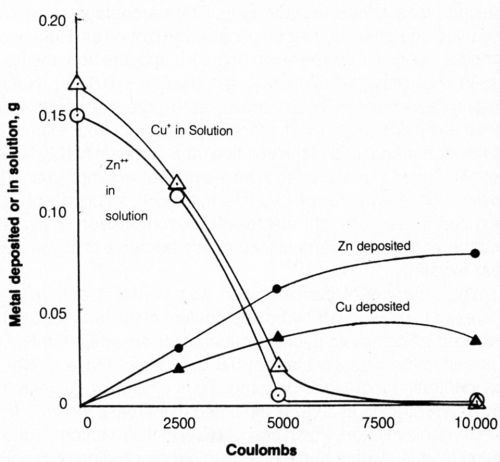
Figure 14 - Effect of quantity of electrolytic current on metal deposited or remaining in solution. Bath was operated at 25°C using 2500 coulombs, using mild agitation (150 rpm) and an anode current density of 20 mA/cm2. The 500-mL solution contained 1.0 g/L NaCN + 0.8 g/L NaOH + 4 g/L NaCl + 0.298 g/L Zn+2 or 0.334 g/L Cu+.
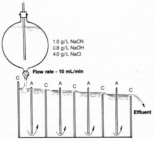
Figure 15 - Diagram of test cell for continuous decomposition of cyanide at 3 A (anode current density was 20 mA/cm2) and 25°C. Anodes (A) and cathodes (C) were connected in parallel.
Concluding remarks
In closing, I'd like to acknowledge the beneficial influences that my years of association with AES have had on my career. Every AES conference was a seedbed of new ideas that were often valuable for improving our shop operations or for indicating new approaches to R&D studies. For example, my interest in beryllium was initiated by a discussion at an AES conference in Boston and resulted in an approved and funded project on protective coatings for beryllium. I could cite many more examples where I have personally benefited from the society.
It would, in turn, be most gratifying if someone would come away from this lecture stimulated by some of the discussion to initiate or conduct additional studies that would lead to practical applications or technological advances.
Again, my sincere thanks to AES for being there when needed; may the excellent job by the officers and headquarters staff continue. To all of you, thanks for your friendships and for according me the honor of this occasion.
Acknowledgments
I wish to acknowledge the contribution of Robert F. Weightman, now retired, in most of the electroless plating projects, as well as the participation of Margaret D'Ambrosio and Dr. James Mikula of the Army Research & Development Center, Dover, NJ, in the cyanide decomposition work. Most of the work described here was conducted while employed at the U.S. Army, Frankford Arsenal, Pitman-Dunn Labs., Philadelphia.
References
1. A. Brenner and G.E. Riddell, J. Res. Nat'l. Bur. Stan., 37, 31 (1946); Proc. Am. Electroplat. Soc., 33, 23 (1946).
2. F. Pearlstein, Met. Fin., 53, 59 (Aug. 1955).
3. C.R. Shipley, U.S. patent 3,011,920 (1961).
4. F. Pearlstein, American Machinist, 102, 110 (Jan. 1958).
5. F. Pearlstein and R.F. Weightman, Electrochemical Technology, 6, 427 (1968).
6. G. O. Mallory and T.R. Horhn, Plating and Surf. Fin., 66, 40 (Apr. 1979).
7. F. Pearlstein, U.S. patent 3,222,196 (1965).
8. F. Pearlstein and R.F. Weightman, Plating, 60, 474 (1973).
9. F. Pearlstein and R.F. Weightman, Plating, 58, 1014 (1971); 61, 154 (1974).
10. F. Pearlstein and R.F. Weightman, Proc. Frankford Arsenal Technical Symposium (1974).
11. R.M. Lukes, Plating, 51, 969 (1964); 51, 1066 (1964).
12. A. Brenner and G.E. Riddell, J. Res. Nat'l Bur. Std., 39, 385 (1947) ; Proc. Am. Electroplat. Soc., 34, 156 (1947).
13. F. Pearlstein and R.F. Weightman, J. Electrochem. Soc., 121, 1023 (1974).
14. F.R. Morral, Plating, 59, 131 (1972).
15. F. Pearlstein and R.F. Weightman, Plating, 56, 1158 (1969).
16. R.N. Rhoda, Trans. Inst. Met. Fin., 36, 82 (1959); J. Electrochem. Soc., 108, 707 (1961).
17. A. Sergienko, U.S. patent 3,418,143 (1968).
18. A. Gallaccio, F. Pearlstein and M.R. D'Ambrosio, Met. Fin., 64, 50 (Aug. 1966).
19. F. Pearlstein and M.R. D'Ambrosio, Plating, 55, 345 (1968).
20. F. Pearlstein and L. Teitell, Materials Performance, 13, 22 (March 1974).
21. F. Pearlstein, R. Wick and A. Gallaccio, U.S. patent 3,485,682 (1969).
22. F. Pearlstein, R. Wick and A. Gallaccio, Met. Fin., 64, 78 (Jan. 1966).
23. F. Pearlstein, Plating and Surf. Fin., 66, 41 (March 1979).
24. H. Brown and B. B. Knapp, Modern Electroplating, 3rd ed. Chap. 12, John Wiley & Sons, Inc. (1974); p. 287.
25. F. Pearlstein and L. Teitell, Materials Protection and Performance, 10, 30 (Nov. 1971).
26. L. Gruss and F. Pearlstein, Plat. and Surf. Fin., 70, 47 (Feb. 1983).
27. C.C. Cohn, Colonial Alloys Co., private communication, circa 1957.
28. K.H. Dale, Plating, 59, 843 (1972).
29. F. Pearlstein, Met. Fin., 58, 40 (Aug. 1960).
30. F. Pearlstein and M.R. D’Ambrosio, Proc. Frankford Arsenal Technical Symposium (1976).
31. D.G. Gardner, R.F. Muraca and E.J. Serfass, Plating, 43, 743 (1956).
32. P&SF Staff Report, Plating & Surface Finishing, 70 (3), 34 (1983).
Footnotes
*I hope my friend Fielding Ogburn of the National Bureau of Standards will forgive me. The "in.2" unit was used for emphasis: 7000 A/dm2 is in keeping with the preferred metric units.
**Triton X-100, Rohn & Haas Corp., Philadelphis, Pennsylvania 19137.
About the author:
This piece was written at the time Mr. Pearlstein was announced as the recipient of the 1982 Scientific Achievement Award.

Today, he is supervisor of the Technical Services Section of the Preservation and Packaging Branch, U.S. Navy. His group is responsible for ensuring that major spare parts for naval aircraft can withstand the rigors of shipment and adverse storage conditions without losing the capability to function when placed in service. From 1952-77, he was employed by the Frankford Arsenal Pitman-Dunn Research Lab., where he initiated, directed, and conducted applied research and investigations in the areas of electrolytic and autocatalytic deposition, corrosion prevention of metals, electrochemical machining of hard metals, and pollution abatement at Army metal finishing facilities. He also has served as a consultant to various governmental agencies and contractors to solve finishing problems encountered in the production of military equipment.
Mr. Pearlstein has published more than 40 papers in the technical literature, including a chapter in Modern Electroplating (3rd edition), and holds 11 patents on subjects relating to surface finishing. He also participated with a group in writing the Handbook on Coatings for Corrosion Prevention of Military Equipment, published by the National Association of Corrosion Engineers (NACE). Mr. Pearlstein received his B.S. degree in chemical engineering from Drexel University in 1949.
The award winner has conducted many R&D studies on electrolytic and chemical finishes. Specifically, Mr. Pearlstein:
- Developed an improved sealing process for anodic coatings on highly corrodible, high-strength aluminum alloys. The process greatly improved corrosion resistance on military equipment exposed to aggressive environments.
- Developed a bath composition for applying chromate conversion coatings to beryllium components of aerospace equipment, providing for protection against both environmental corrosion and high-temperature oxidation. He also developed processes for anodizing beryllium and elucidated the high-temperature oxidation mechanism.
- Designed a plating device and developed a process for safely and effectively depositing radioactive silver plus cadmium.
- Studied the feasibility of improving corrosion resistance by applying a unique double-layer system comprised of an initial layer at low cathode current density (CCD) and a top layer at high CCD from a single bath. Promising results were obtained, especially with certain alloy plating baths.
- Investigated the electrophoretic deposition of powdered metals from suspension and developed the process producing protective aluminum deposits on steel.
- Determined the mechanism of adverse effects of heat on the corrosion resistance of chromate films and devised promising processes for reducing these effects on chromated zinc or aluminum.
Mr. Pearlstein's work in the field of electroless deposition also has been extensive. He developed a process in 1955 for activating non-conductors using SnCl2 and PdCl2 immersions for the purpose of metallizing plastic dipoles of proximity fuses with electroless nickel. In the area of electroless copper, he developed a bath of considerably improved stability, compared with available commercial solutions at the time (1962), for practical use in the manufacture of PC boards. He also came up with an electroless copper amine-borane-based solution less aggressive than the highly alkaline formaldehyde bath toward sensitive substrates. Deposits were adherent to steel and therefore a potential alternative to the cyanide copper strike.
His additional endeavors in the field of electroless deposition are as follows. He:
- Developed a bath for electroless silver plating on the interior surfaces of wave guides.
- Developed baths for the electroless deposition of palladium and Pd-Ni alloy as potential cost-effective alternatives to gold deposits for electronic applications.
- Developed an acidic bath for the electroless deposition of cobalt to eliminate the undesirable ammonia vapors associated with conventional solutions. Alkaline cobalt baths were modified to provide a range of useful magnetic properties.
- Accomplished electroless deposition of ternary and quaternary alloys to provide a variety of chemical, physical and mechanical properties for specific applications, while enabling advantage to be taken of the benefits inherent in the autocatalytic process.
- Developed double-layer electroless systems that proved effective for improving corrosion resistance and reducing high-pressure wear.
Mr. Pearlstein also has been active in pollution-abatement operations at Army facilities. For example, a waste-treatment system at one munitions plant was strained beyond handling capacity, owing to an excessive effluent volume generated from a continuous spray-phosphating line to treat steel projectiles. He directed the incorporation of fogging sprays at "drain" stages after spray alkaline cleaning and phosphating, modified the existing rinse tanks into two separate compartments, and separated the spray-riser manifold into two sections so that the spray rinses were in a double-counterflow mode. Implementation was made at nominal cost and resulted in an 88% decrease in water consumption, conservation of treatment chemicals (reduced dragout losses by 80%), and more effective waste treatment (from decreased effluent volume and greater contaminant concentration). Primarily for this work, but including background laboratory work, Mr. Pearlstein was nominated by the Frankford Arsenal for the Army Research and Development Achievement Award in 1976.
Fred Pearlstein has been a leader in the AES for many years. During his service with the Education Committee, he participated in initiating and conducting the first AES Intensive Training Course and the Certified Electroplater-Finisher (CEF) program. He is currently chairman of the Paper Awards Committee and the author of "Test Your Plating I.Q.," a monthly feature in P&SF. Finally, he is the instructor of a four-semester electroplating course at Temple University's College of Engineering Technology and is an accredited corrosion specialist of NACE.
RELATED CONTENT
-
Electroless Nickel Coatings: Appearance, Gloss and Surface Morphology
For decorative coatings, appearance is the essential purpose for application, but also for functional surface finishes it becomes increasingly relevant as an added value on top of specified technical requirements. Appearance is affected by spectrum and intensity of incident light, roughness and morphology of the coating surface, optical properties of the coating material, eventual superficial oxide films, and individual perception. The predominant factor is surface roughness, which in turn depends on base material roughness, quality of substrate pretreatment, and nucleation and growth kinetics of the electroless nickel (EN) deposit. Interdependency of gloss measurements with roughness measurements and with chemical composition of coatings was investigated for new generation mid-P EN processes and compared to traditional ones.
-
Aluminum Surface Finishing Corrosion Causes and Troubleshooting
In this paper, a review of several process solutions, examining coolants, solvent cleaning, alkaline clean/etch and deoxidizing/desmutting, listing intended and unintended chemical reactions along with possible mechanisms that would favor corrosion formation.
-
Identifying New Alternatives for Chromium Plating
A comprehensive review of chromium plating alternatives and a new look at a long-forgotten but potentially important process - iron plating


