Test Methods For Evaluating Anodized Aluminum
Benefits of anodizing include durability, color stability, ease of maintenance, aesthetics, cost of initial finish and the fact that it is a safe and healthy process. Maximizing these benefits to produce a high–performance aluminum finish can be accomplished by incorporating test procedures in the manufacturing process.
#measurement-testing
Film Thickness Measurement
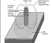
The most common means of measuring the thickness of anodized aluminum is the Eddy Current Method (Figure 1). The Eddy Current Method uses a probe that contains a coil. This probe/coil is driven by a high–frequency oscillator to generate an alternating high-frequency field. When this field is brought near a metallic conductor, eddy currents are generated in that conductive material that results in the impedance change of the probe coil. The distance between the probe coil and the conductive substrate material determines the amount of impedance change. Therefore the coating thickness is determined by the impedance change in the form of a digital reading. Common applications include liquid or powder coating over aluminum and non-magnetic stainless steel as well as anodize over aluminum.
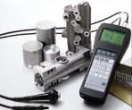
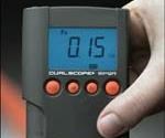
There are multiple options to choose from with regard to selecting a unit to measure anodize thickness. Typical hand-held instruments have a built-in integral probe or a probe on a cable. Bench top units are also available for even more detailed evaluation of coating thickness. A built-in probe (Figure 2) is ideal for a continuous coil anodizing process where a large measurement area is typical. A unit with a separate probe (Figure 3) is more suitable for a batch anodizing process where parts of many shapes and sizes are common. Some systems combine the most commonly used test methods in a single measuring system. In these instances, the measuring system operates according to the selected test method by using specific probes and corresponding test modules.
Featured Content
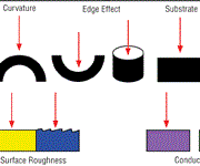
Regardless of the type of coating thickness instrument used, the end user should be aware of factors that can influence anodize thickness readings. Influences in coating thickness measurement can affect the accuracy of the reading. Some of these influences include distance to the edge of the part, surface curvature, thickness of substrate, heat treatment, surface roughness, and contact force (probe pressure). Additional information on these influences can be found in ASTM Standard B 244. Figure 4 summarizes these influences while the following definitions of these influences as described in the ASTM B 244 are quoted below.
Curvature—Measurements are affected by the curvature of the test specimen. The influence of the curvature varies considerably with the make and type of instrument, but always becomes more pronounced as the radius of curvature decreases. Advancements in technology however have enabled the development of a special probe that eliminates the influence on curvature on coating thickness measurement.
Edge Effect—The method is sensitive to abrupt changes in the surface contour of the test specimen. Therefore, measurements made too near an edge or inside corner will not be valid unless the instrument is specifically calibrated for such a measurement.
Base Metal Thickness—For each instrument, there is a critical thickness of the base metal above which the measurements will not be affected by an increase in the thickness of the basis metal. Since it depends on the instrument probe and the nature of the base metal, its value should be determined experimentally if not supplied by the manufacturer.
Surface Roughness—Measurements are influenced by the surface topography of the base metal and of the coating. Therefore, it is necessary on a rough or scratched surface, to make a greater number of measurements at different positions to obtain a mean value that is representative of the average coating thickness. If the base metal is rough, it may also be necessary to check the zero of the instrument at several positions on a portion of the uncoated rough, base metal.
Conductivity—Eddy Current measurements are affected by the electrical conductivity of the base metal, which itself is often affected by heat treatment.
A corrective calibration can be established to reduce these influences by taking readings of certified foils on the actual substrate that will be in use. This calibration can then be stored in the testing units so that the user does not have to re-calibrate for every part. If the gage offers this capability, the user can select with the press of a button the application that represents the specific calibration.
As previously mentioned, curvature of the substrate influences coating thickness values if not properly calibrated. Practically speaking, this can be difficult if a raw pre-anodized part is not available for calibration. Since tubes and other curved surfaces are commonly anodized, the effects of curvature in coating thickness reading can be particularly troublesome.
By using a special probe design, research has lead to a compensation method that virtually eliminates the curvature dependence and improves the accuracy of the readings. This in turn makes it possible to measure the coatings on different shaped surfaces without having to constantly re-calibrate to a specific part geometry.
Companies that use a batch anodizing process are most likely to encounter curved surfaces. Common batch anodized parts include bent metal parts, castings, cookware, cosmetic cases, flashlight bodies, and machined aluminum parts.
Evaluating the Quality of Seal of Anodic Coating
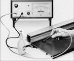
In addition to measuring film thickness, the sealing quality of the coating should be measured. The purpose of measuring the sealing quality is to determine the weather resistance of a finish. Several different methods are available for measurements on decorative anodic finishes of 0.1–0.6 mils, anodic finishes used in the construction industry 0.6–1.3 mils and super hard anodic finishes of .8 and upwards. Figure 5 (right) demonstrates a test in progress.
The measurement procedure includes a self adhesive rubber ring which is placed on the surface to be tested with a few drops of test fluid. The aluminum surface is then connected to the socket of the unit and the test electrode dipped into the cell fluid. This in turn forms a capacitor in which the anodic film acts as the dielectric. It is the admittance of this capacitor that is measured and directly indicated in microsiemens. This process is in accordance with ASTM B 457.
Conductivity Measurement
Electrical conductivity measurement is especially important in determining the strength and hardness of heat-treated materials such as aluminum alloys. Inspecting for heat damage and use of proper aluminum grade is critical in the manufacture, maintenance and repair of aircraft components that contain anodized parts. Another common application for conductivity measurement includes the incoming inspection of alloys to determine the degree of purity. A hand-held conductivity meter is pictured in Figure 6.
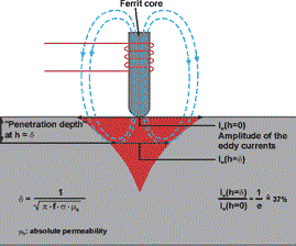
Hand-held meters measure the electrical conductivity using the eddy current method according to ASTM E 1004. The phase-sensitive measurement signal evaluation enables a contact-free determination of the electrical conductivity. This is especially beneficial in identifying the type of alloy even after the part has been anodized. The penetration depth of the eddy currents is established by the measurement frequency (f), which determines the minimum permissible thickness of the specimen. Figure 7 demonstrates the penetration depth of the eddy currents. Some measurement probes are suitable for all four measurement frequencies of 60 kHz to 480 kHz.
Temperature affects the validity of conductivity readings. Therefore, having a temperature sensor integrated or external that automatically compensates for temperature is necessary for measuring electrical conductivity correctly.
The physical correlation between the electrical conductivity and the temperature of the specimen is described by the following equation:
s = s20/[1 + µ (T–20°C) ]
where:
s is electrical conductivity in MS/m
s20 is electrical conductivity at 20°C (68°F)
T= current temperature of the specimen
µ= temperature coefficient of the electrical conductivity or the specimen
Calibration standards are available and traceable to internationally recognized standards. Certification of the stated percent IACS values of the conductivity standards are obtained by comparison to a set of Boeing/USA conductivity standards. Boeing standards are also used and are available in the entire conductivity range. Boeing Conductivity Standards are traceable to the National Institute of Standards and Technology.
Conclusion
Anodizing has several clear benefits over other aluminum finishes. Combined with a quality control program that incorporates common test methods these benefits can be maximized. The most common of these test methods include film thickness measurement, the seal of anodic coatings, and conductivity measurement. Knowing the basics of each method and the influences that affect each method will also enhance the quality of the products being produced.
RELATED CONTENT
-
How to Apply the 720 Rule to Current Density Anodizing
What can you tell me about the 720 Rule as it applies to current density anodizing? Plating expert Sjon Westre, Ph.D., from Chemeon, answers this question.
-
Cleaning, Pretreatment to Meet Medical Specs ISO 13485 or FDA 21 CFR820
Maximilian Kessler from SurTec explains new practices for industrial parts cleaning, metal pretreatment and decorative electroplating in the medical device industry.
-
Fixing Corrosion Between Anodized Aluminum and Steel
Anne Deacon Juhl, Ph.D., with AluConsult, says Galvanic corrosion is due to an electrical contact with a more noble metal or a nonmetallic conductor in a conductive environment.


