The Rotating Cylinder Hull Cell: Design and Application
In our first paper this month, featuring the latest work from AESF/NASF Research, the rotating cylinder Hull cell (RCH) was used to study the behavior of a Ni-Mo-W plating bath. Originally published in 1993, this second paper outlines the basic concepts and work behind the development of the RCH cell.
#basics #nasf
by
C. Madore and D. Landolt
Featured Content
Laboratoire de Metallurgie Chimique
Lausanne, Switzerland
Originally published as:
Plating & Surface Finishing, 80 (11), 73-78 (1993).
Editor’s Note: A printable PDF version is available by clicking HERE.
ABSTRACT
A new cell geometry, the RCH cell, can replace the classical Hull cell in applications where mass transport is of importance. The cell includes a rotating cylinder electrode and an asymmetrically placed counter-electrode with a suitably placed concentric separating wall. The primary current distribution resembles that of the classical Hull cell. The usefulness of this cell design is demonstrated by studying the reaction distribution on the cathode during deposition of a copper nickel alloy from a citrate-based model electrolyte.
Introduction
The Hull cell1 is a trapezoidal structure in which the cathode is placed at an oblique angle with respect to the anode. The cell allows exploration of the variation in the appearance of an electrodeposit over a wide range of current densities along the cathode surface in order to determine optimal electroplating conditions. It is commonly used for maintenance of plating solutions to insure continuous production of satisfactory deposits and for the development of new electrolytes. A shortcoming of the traditional Hull cell is the absence of controlled mass-transport conditions. Indeed, for many plating processes, mass transport is a crucial step; examples include metal plating in the presence of leveling agents or alloy plating with one component being present in low concentration. In such cases, interpretation of a Hull cell plate is difficult and the cell cannot be used effectively.2
To overcome this problem, several authors have proposed Hull-type cells that include controlled hydrodynamic conditions. Graham and Pinkerton built a rotating cylinder placed coaxial with a stationary conical anode.3 The current distribution along the cathode examined in their studies, however, was significantly more uniform than that obtained in the traditional Hull cell. Kadija, et al. developed a hydrodynamically controlled Hull cell using a rotating cylinder with the anode placed below the cathode on the cylinder.4 Using a partially submerged cathode and insulator baffles, they obtained a current distribution similar to that of the Hull cell. In this cell, however, a well-defined current distribution is obtained only if effects resulting from a vortex can be avoided. Lu proposed several designs using conical and cylindrical electrodes.5 The described cell configurations, however, were either empirical or of complex geometry and therefore had limited applicability.
In the absence of mass-transport effects, uniformity of the current distribution in electrochemical cells depends on the ratio of the polarization resistance at the electrode surface and the ohmic resistance of the electrolyte. This ratio is expressed by the Wagner number. For Tafel kinetics, the Wagner number is given by Equation 1:
(1)
where η is the overpotential, ρe is the electrolyte resistance, κ is the electrolyte conductivity (κ = 1/ρe), iavg is the average current density, and L is a dimensionless length, here the cathode length h. The most non-uniform current distribution, the so-called primary current distribution, corresponds to Wa 0. The empirical Eq. (2) used in practice for the determination of the current distribution i on the classical Hull cell corresponds to this case.6
(2)
where z is the dimensionless cathode length measured from the low current end and iavg the average current density in the cell. The insensitivity of practical Hull cell experiments to kinetic parameters is readily understood with Eq. (1) because the evaluated average current density is usually quite high, leading to a value of Wa close to zero.
The goal of the present study is to design an alternative Hull cell having a primary current distribution close to that of the classical Hull cell, but with well-characterized mass-transport conditions. The mass-transfer rate should be uniform over the entire cathode surface and the magnitude of the limiting current should be easily varied. The new cell should be relatively simple to build and to use, without the need for elaborate pumping systems or of a large electrolyte volume. Its primary and secondary current distribution should be well known from numerical simulation.
Cell geometry
Theoretical and practical design considerations of a cylindrical Hull cell with controlled convection have been published in a recent paper.7 In the present investigation, a simple cell design is described and its performance tested with two model systems - electrodeposition of copper at almost primary current distribution, and electrodeposition of a copper-nickel alloy involving mass-transfer-controlled deposition of copper. The cell consists of a rotating cylinder electrode with a counter-electrode placed at one end. An outer stationary insulating separator is placed coaxially with the rotating cylinder electrode and its diameter determines the current distribution along the cylinder electrode. The primary current distribution was simulated for the above geometry with a software based on a boundary element method (BEM).8,9 The cell geometry was optimized in order to yield a current distribution similar to that of the Hull cell.7 The optimal geometry was found to correspond to a ratio of the electrode length over the distance between the electrode and the insulating separator equal to three. Moreover, the calculations showed that position of the anode, placed outside the insulating separator, has no influence on the current distribution.
Figure 1 compares the primary current distribution for the optimal geometry of the RCH cell described above and the Hull cell. The two distributions are quite similar. For small values of z, the current density in the RCH cell varies slightly less than in the Hull cell because the current density at the far end does not go to zero. The simulated primary current distribution for the RCH cell is described by the following expression:7
(3)
where z is the dimensionless distance along the cathode from the lowest current density side (z = l - x/h in Eq. [9] of Ref. 7), i(z) the current density along the cylinder cathode and iavg the applied current density.
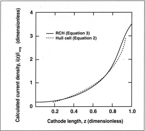
Figure 1 - Primary current distribution for the RCH cell given by Eq. (3) and for the Hull cell, Eq. (2).
An experimental cell that fulfills the above geometric considerations was built and is shown schematically in Fig. 2. The cylindrical cell, made of Plexiglas™, is 135 mm in height and 120 mm in diameter. A cylindrical Plexiglas separator, 85 mm in height and 55 mm in inner diameter is fixed concentrically at the bottom endplate. The motor shaft and the rotating cylinder assembly are held concentric with the separator by a Teflon guide attached to the top endplate. This design facilitates the removal of the electrode. The rotating assembly is supported from below with a guide pin in order to avoid eccentric motion. The electrode is submerged about 4 cm below the electrolyte surface and its top end is located 1 cm below the upper edge of the cylindrical separator. In this configuration, all the current between anode and cathode flows through the open space at the top of the separator. The current density, therefore, is maximum at the top end of the cathode and diminishes continuously toward its lower end. In a previous design, the insulating separator had been placed so that the maximum current density was reached at the bottom of the cathode.10 An advantage of the present design is that gas bubbles, which sometimes form at the cathode at high current density, can leave the electrode surface without disturbing the reactions proceeding on the low-current-density part of the surface. Figure 3 shows a photograph of the present cell assembly, including motor, rotating cathode and stationary counter-electrode. The latter is an oxide-coated commercial titanium mesh placed concentrically, outside the cylindrical separator. Other anode materials in the form of sheets of meshes can also be employed.
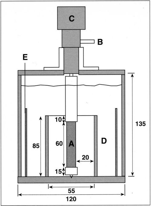
Figure 2 - Schematic of the RCH cell. The cylinder cathode (A) is connected electrically through a silver friction contact (B) and is attached to the motor (C). Insulating separator (D) is fixed concentrically with the cylinder cathode. Concentric anode (E) is placed outside the insulating separator. Dimensions in mm.
The rotating cylinder assembly is shown in more detail in Fig. 4. It consists of an aluminum shaft 13 cm in length. The electrical contact between the rotating electrode and the current source is provided by a silver friction contact. The electrode is a hollow metal cylinder 6 cm in length and 1.5 cm in diameter, which fits on the shaft. The cathode surface is recessed by 0.25 cm with respect to the surface of the insulating sleeves that cover the rotating shaft above and below the active electrode surface. The recess prevents the primary current distribution at the near edge going to infinity. Mass transport is not measurably changed by the presence of a recess.10 The electrode surface area is 28.3 cm2. The upper part of the shaft is covered with Teflon™ insulation 5.5 cm in length. A1.5-cm Nylon™ part is screwed onto the lower end of the shaft. It holds the electrode in place and permits its easy removal. The upper end of the rotating cylinder is attached to the motor shaft. The motor velocity is electronically controlled with an optical feedback sensor and can be operated in the range of 50 to 3600 rpm. The velocity is stable within 5 percent, at rotations below 300 rpm and within 2 percent at higher speeds.
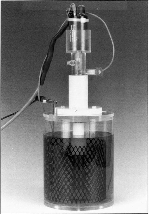
Figure 3 - RCH cell.
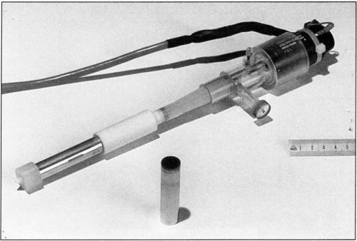
Figure 4 - Rotating electrode assembly.
Verification of current distribution
To verify the primary and secondary current distributions at the cathode in the absence of mass-transport effects, copper was deposited much below its limiting current density. Deposition was carried out from an acid sulfate bath containing 0.6M CuSO4 and 1.0M H2SO4, prepared from reagent-grade chemicals and doubly-distilled water. A high copper concentration was used to minimize the influence of mass transport and a high acid concentration used to increase bath conductivity and prevent oxide formation at the anode. All deposits were plated at a constant temperature of 25°C, using a cylinder rotation speed of 900 rpm. The cathode was a nickel cylinder and the anode was a pure copper sheet. Prior to deposition, the nickel cylinder was polished with 600 grit sandpaper, washed with soap and rinsed with distilled water.
Deposition was performed galvanostatically at an average current density of 100 mA/cm2. The total charge passed through the cell was 693°C, corresponding to an average deposit thickness of 9.3 µm. The current density employed corresponded to about 20 percent of the limiting current density. Consequently, the effect of mass transport could be safely neglected. Current efficiency for copper deposition as measured by weight gain experiments was found to be approximately 100 percent for all deposits. Copper thicknesses along the electrode length were measured by x-ray fluorescence (XRF).
Simulation of the secondary current distribution was performed with a BEM method, using Tafel kinetics as boundary conditions at the cathode.9,10 A cathodic Tafel constant of βc = 45 mV, an exchange current density io of 2 mA/cm2, and an electrolyte resistance of 0.35 Ω-cm2 were measured for a 0.5M copper sulfate acid electrolyte at 25°C.10 These values were used in the calculations. For the cell used, these deposition conditions correspond to a Wagner number of 0.02.
In Fig. 5, the experimentally measured dimensionless thickness µ(z)/µavg and the calculated dimensionless current density i(z)/iavg are represented as a function of the dimensionless length z along the cathode. The deposit thickness is related to the current density through Faraday's law:
(4)
where M is the atomic weight of copper and ρ its density. For a current efficiency of 100 percent, the dimensionless thickness µ(z)/µavg corresponds exactly to the value of i(z)/iavg. Good agreement was found between the computed secondary current distribution and the experimental data showing the variation of deposit thickness with distance from the upper edge. The slight difference in the computed curves for primary and secondary current distribution suggests that kinetic effects were not entirely negligible at the average current density of 100 mA/cm2. However, the secondary current distribution is very close to the primary case and the metal distribution can be approximated by Eq. (3). For many practical applications of the RCH cell at low Wa, Eq. (3) should be sufficiently accurate for estimation of the local current density.
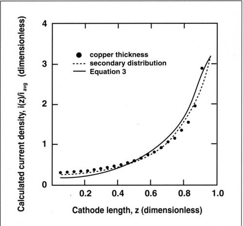
Figure 5 - Experimental and theoretical current distribution along the cylinder cathode. The secondary distribution is calculated for a Wagner number of 0.02; the primary distribution is calculated by Eq. (3). Current densities and lengths are dimensionless.
Alloy deposition involving a mass transport-limited step
To demonstrate the usefulness of the RCH cell for alloy deposition applications, copper-nickel alloys were deposited from a citrate-model electrolyte, containing a large excess of nickel. The bath was composed of 0.25M Na3C6H5O7•2H2O, 0.7M NiSO4•6H2O and 0.025M CuSO4•5H2O dissolved in doubly-distilled water. This electrolyte composition contains a low copper concentration in order to facilitate mass-transport control of the copper deposition reaction. The copper content in the electrolyte was monitored by atomic absorption and was kept constant within 10 percent. The cylindrical cathode was made of stainless steel. Because copper and nickel did not adhere well to the substrate, a 0.5-µm-thick gold electroplate was deposited on the base metal to produce adherent deposits. A DSA mesh anode was used in order to avoid a change in the electrolyte composition by anode dissolution.
Deposition was performed galvanostatically at 25°C at an average current density of 25 mA/cm2, and the average deposit thickness was 9.3 µm. The thicknesses and compositions of the alloys were analyzed by XRF and the partial current densities for Cu and Ni were deduced from the analysis. The partial current for hydrogen was negligible on most parts of the cathode. The effect of mass transport on the alloy composition was investigated by varying the rotation speed from 300 to 1500 rpm and the copper content in the electrolyte from 0.01M to 0.038M.
Results
A wide range of alloy compositions was obtained in a single experiment because of non-uniform current distribution at the cathode. The change in composition could be readily seen from the color of the deposit, which varied from red at the low-current-density end to gray at the high-current-density end. Compact deposits were obtained for copper concentrations less than 80 percent. At higher copper contents, dark-red and slightly powdery deposits were formed. A black powdery deposit was obtained near the high-current-density edge of the cathode where some hydrogen evolution occurred during deposition. This region of the cathode could not be analyzed by XRF.
The variation in alloy composition along the cylinder is shown in Fig. 6. The copper content in the electrolyte was 0.025M and the cathode was rotated at 600 rpm. The deposit thickness increased from 2 µm to 20 µm with increasing current density. The corresponding variation in composition was 75 percent Cu to 10 percent Cu.
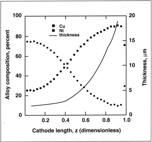
Figure 6 - Variation in thickness and composition along the cylinder cathode for a copper-nickel alloy. Deposition performed at 25 mA/cm2 average current density, 600 rpm and 0.025M Cu+2.
The alloy composition is also dependent on mass-transport conditions. The dependence of copper current density with rotation speed is shown in Fig. 7 for a copper concentration of 0.025M. The copper partial current density follows a straight line when plotted against the rotation speed. A linear relation is also observed when the copper current density is plotted against the copper concentration in the bath (Fig. 8). This shows that copper deposition is mass-transport limited and follows the Eisenberg, Tobias and Wilke correlation12 at a rotating cylinder electrode in a turbulent flow regime:
(5)
where CCu+2 is the copper concentration in the electrolyte (mol/cm3), n the rotation speed (rpm) and K is a proportionality factor given by:
(6)
where ilim is the limiting current density, d the cylinder diameter, D the diffusion coefficient and ν the kinematic viscosity. Linear regression of the above relation yields a slope (averaged for the four electrolytes) of K = 1.4. Based on a kinematic viscosity of 0.01 cm2/sec, a diffusion coefficient is computed for the copper-citrate complex of 1 × 10⁻⁶ cm2/sec. This value is lower than the diffusion coefficient of copper sulfate (5 × 10⁻⁶ cm2/sec) and suggests that Cu+2 is probably complexed.
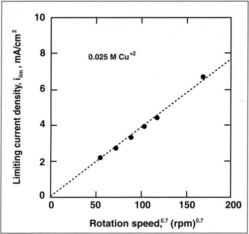
Figure 7 - Variation of limiting current density for Cu+2 with rotation speed for a copper concentration of 0.025M.
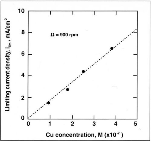
Figure 8 - Variation of limiting current density with concentration of Cu+2 for a rotation speed of 900 rpm.
Figure 9 shows dimensionless partial currents for nickel and for copper along the cathode as determined from the data of Fig. 6. The copper current is constant and equal to its mass-transfer-limited value over the entire length of the cathode, while the nickel current is a function of the position along the cathode. The total current is obtained by summing the measured current for nickel and the limiting current for copper. The partial current for hydrogen was neglected. The current for nickel was calculated assuming Tafel kinetics because the nickel ion concentration in the electrolyte was high, and therefore, mass-transport effects could be neglected. The simulated curve is obtained by summing the calculated current for nickel and the limiting current for copper. For nickel deposition, a conductivity of 0.04 S/cm and a Tafel slope of 0.13 V/decade (βc = 57 mV) were assumed in the calculations. These values were measured in independent experiments. For L = 6 cm (cathode height) and iavg = 21 mA/cm2, the corresponding Wagner number is 0.02. Therefore, the partial current distribution for nickel is almost primary. As a result of the small copper concentration in the electrolyte, the assumption that copper, the more noble metal, deposits under mass-transport control is justified. The results of Fig. 9 show excellent agreement, confirming the assumptions made.
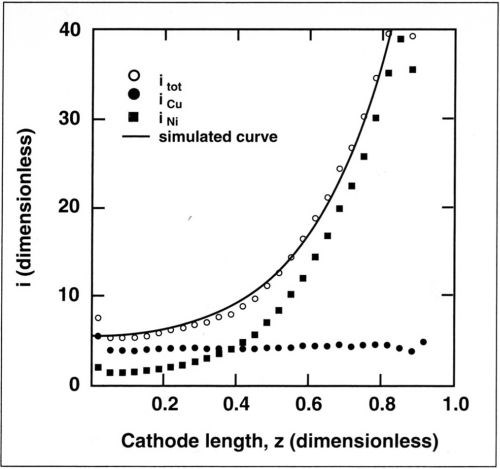
Figure 9 - Measured partial currents for copper and nickel deposition along the cathode for an average current density of 25 mA/cm2. Also shown is the total current density calculated with the measurements (points) and by numerical simulation (line). Copper content, 0.025M; rotation speed, 600 rpm.
The model involving a more noble metal (copper), depositing at its limiting current density, and a less noble metal (nickel), depositing following Tafel kinetics is schematically presented in Fig. 10. In such a case, the alloy composition depends on both the applied current density and agitation of the bath. For the RCH cell, the variation of alloy composition with position can be theoretically predicted for a given average current density and rotation rate. Because of unknown mass-transport conditions, this is not possible for the classical Hull cell. In the present study, it has been assumed that codeposition proceeds independently for the two metals and that the partial current densities can simply be added. In many alloy plating processes, for example, those involving anomalous codeposition, this assumption is not valid. The RCH cell should nevertheless be useful for the study of such processes because of its controlled mass-transport conditions.
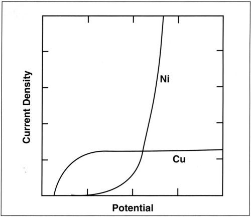
Figure 10 - Variation of the partial currents for copper and nickel deposition with potential (schematic).
Summary and conclusions
A new cell design, the RCH cell, has been described and tested, which can advantageously replace the classical Hull cell for electrodeposition applications involving one or several mass-transport-controlled reactions. The RCH cell consists of a rotating cylinder cathode and a counter-electrode placed asymmetrically. Using numerical simulation, the RCH cell geometry has been optimized in such a way that the primary current distribution corresponds closely to that of the conventional Hull cell. The use of a rotating cylinder cathode gives uniform and well-controlled mass-transport conditions. Owing to its simple design, the RCH cell can be built easily in the laboratory and is relatively inexpensive. The deposition of a copper-nickel alloy from a citrate bath has been used to demonstrate the importance of mass transport for the reaction distribution on the cathode. For this type of application, the RCH cell is clearly superior to the classical Hull cell.
Acknowledgment
This work was financially supported by OPEN, Bern, and by Fonds National Suisse, Bern, Switzerland. The authors thank M. Matlosz for helpful discussions and R. Dabbous for experimental assistance.
References
1. R.O. Hull, AES Monthly Review, 26, 753-767 (Oct. 1939).
2. W. Hohse, Die Untersuchung galvanischer Bader in der Hull Zelle, 3rd ed., Eugen G. Leuze Verlag, Saulgau/ Wurtt, Germany, 1984.
3. A.K. Graham and H.L Pinkerton, "A Cell for High-Speed Plating Evaluations," Tech. Proc. Am. Electroplaters Soc., 50, 135-138 (1963).
4. I. Kadija, J.A. Abys, V. Chinchankar and H.K. Straschil, Plating and Surf. Fin., 78, 60-67 (July 1991).
5. Po-Yen Lu, Plating and Surf. Fin., 78, 62-65 (Oct. 1991).
6. Norm 50957 DIN (Deutsches Institut fur Normung), GalvanisierungsprufungmitderHull-Zelle, TAB 175, Beuth Verlag GmbH, Berlin, Koln (1983).
7. C. Madore, A.C. West, M. Matlosz and D. Landolt, Electrochemica Acta, 37, 69-74 (1992).
8. C.A. Brebbia, J.C.F. Telles and LC. Wrobel, Boundary Element Techniques, Theory and Applications in Engineering, Springer-Verlag, Berlin, 1984.
9. M. Matlosz, C. Creton, C. Clerc and D. Landolt, J. Electrochem. Soc., 134, 3015-3021 (1987).
10. C. Madore, A.C. West, M. Matlosz and D. Landolt, J. Appl. Electrochem., 22, 1155-1160 (1992).
11. D.P. Barkey, R.H. Mullerand C.W. Tobias, J. Electrochem. Soc., 136, 2199-2206 (1989).
12. M. Eisenberg, C.W. Tobias and C.R. Wilke, J. Electrochem. Soc., 101, 306-320 (1954).
About the authors (1993)


RELATED CONTENT
-
Polishing vs. Buffing: What's the Difference?
Is polishing the same as buffing? Mechanical finishing expert, Pat Wenino, explains the differences between the two processes.
-
Alkaline Cleaning Guide
Gregg Sanko, Senior Chemist, Oakite Products, Inc. provides an overview of the alkaline cleaning process.
-
Nickel Electroplating
Applications, plating solutions, brighteners, good operating practices and troubleshooting.


