Walking on Air
When increases in production require paint-system expansions, they usually also require more capacity from emissions-abatement systems...
Plant expansions and production increases are clear signals that a company is healthy and growing. But good news for the company often translates into some interesting challenges for facilities engineers. Among them: plant space, new equipment, construction, schedules, capacities, utilities and more.
As paint systems are expanded, more process-ventilation air is exhausted and more solvents are discharged. Increasing the capacity of VOC-abatement systems to handle the additional solvent/air volume is a necessary part of the growth.
Featured Content
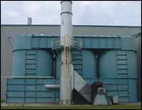
Flex-N-Gate (Ada, OK) is a major tier one supplier of automotive products, and the company produces fascias and claddings for General Motors at its Ada plant. The original plant—purchased by Flex-N-Gate in 2001—was constructed in 1995. A regenerative thermal oxidizer (RTO) was installed with the original paint shop to remove solvent from exhaust air and thus meet emissions regulations. The RTO has been in continuous use for the past eight years, with no significant maintenance service.
The expansion was constructed in 2003 and was planned for completion by the end of the year.
As originally installed, the RTO was connected to the exhaust from spray booths, topcoat ovens and the paint kitchen. The expansion also required connecting air exhausts from a new prime-spray booth and prime oven. Altogether, expansion of the paint system increased the volume of solvent-laden exhaust air from 34,000 cfm to 61,000 cfm.
Flex-N-Gate considered three alternatives to deal with these higher exhaust rates:
- Force more air volume through existing equipment.
- Add new abatement equipment.
- Increase the capacity of existing equipment.
The existing RTO had been reliable and virtually maintenance free for many years. It had met the performance and operating cost criteria originally promised. So Flex-N-Gate decided it was in the company’s best interest to find a way to continue to use the existing RTO, modifying it to accommodate the increased volume.
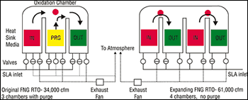
As demonstrated in Figure 1, the design of this RTO consists basically of an oxidation chamber with burners, regenerative thermal recovery chambers, a system to periodically change the air flow through the regenerative chambers and a fan to move the air. Physical size of the RTO is a direct function of exhaust volume. It is affected by the heat-recovery media and its optimum face velocity. This in turn is affected by the pressure across the media as well as the heat storage and release characteristics. Typically, RTOs are built to handle a specific air volume.
Other design factors that had to be considered:
- Burner capacity and placement, to assure uniform temperature distribution at the selected destruction temperature, usually around 1500°F.
- Size of valves and manifolds for the air volume.
- Residence time is a particularly important factor. It is the minimum time for the process air to move from the hot side of one regenerative bed to the hot side of an adjacent regenerative bed. This is usually 0.5 second, which is determined by making air at oxidation temperature travel the shortest path between the chambers.
- Turbulence of the air during oxidation contributes to maximum destruction efficiency (DE). As VOCs oxidize, oxygen around the solvent gases is depleted and turbulence continuously mixes the remaining VOCs with avail- able oxygen in the combustion zone. Oxidation occurs in two areas: in the oxidation chamber mixing is caused by the cyclical changes of air flow from one inlet or outlet to another set of inlet outlet regenerative chambers, and some oxidation begins within the heat sink beds as the gas temperature reaches the auto ignition temperature of the VOCs. Mixing in the heat sink bed is most effec- tive in media that does not have long straight passages. Saddles and corrugated media work well for this. An air- mixing type of heat- sink media, such as saddles, functions well in such an application.
-
Number of regenerative chambers. This involves two considerations: air volume (and its effect on practical construction and shipping sizes) and the destruction efficiency. DE below 98% usually can be attained using an even number of chambers. For higher DE, another chamber is required. The odd number of chambers allows purging between inlet and outlet cycles.
Exploring the Options
Two practical opportunities exist for moving more process air through the RTO. The engineer can change the heat-recovery media to one that has less pressure drop while still functioning effectively as a heat sink; or he can add another regenerative chamber to increase the cross sectional area of the regenerative beds. In either case, the fan would have to be modified to handle the additional volume, and the burner capacity would have to be increased.
The original RTO at Flex-N-Gate was constructed to be expanded in the future to handle up to 72,000 cfm by adding regenerative chambers, burners and an additional exhaust fan. The heat sink media in the regenerative chambers was one-inch ceramic saddles at a depth of 7.5 ft.
After evaluating the RTO volume increase options, Flex-N-Gate considered removing the existing heat sink saddles and installing ceramic structured packing. This packing, often called honeycomb, is an extruded material installed in square blocks. The blocks have square holes running through them, usually in an array of 40x40 cells in a 6x6-inch block. This material has had fairly good success in similar applications. Although it is comparatively fragile, it has less pressure drop across the heat sink bed than saddles and therefore allows more air to pass through.
Installing the structured packing would involve removing the saddles from all three regenerative chambers, modifying the supports and then carefully installing the blocks to a depth of approximately five feet. Additional burner capacity would be required to maintain the 1,450°F oxidation temperature needed for complete VOC destruction. The existing exhaust fan would be modified to deliver the new air volume.
Based on this approach the RTO would be expected to have a pressure drop across two heat sink beds of approximately 10 -11 inch wc, and a thermal recovery of 94-95%. This is assuming an inlet air volume of 61,000 scfm at 100°F and an oxidation chamber temperature of 1,450°F.
Installation time would be critical. Available RTO shut down periods were limited and indeterminate. All work would have to be done during a unit shut down period; remove the saddles, rework the supports, increase the burner capacity, modify the fan and start up and adjust the system.
Another Answer
Another option was presented by Salem Savard, Detroit, MI, whose engineers were involved in the original RTO design and construction. Using three chambers allows higher destruction efficiency than constructing with two chambers. A look at the permit requirements disclosed that the system is acceptable at 97% DE, and it was determined that this would be achievable in an RTO that has no “odd” chamber for purging.
Salem Savard—which was ultimately awarded the project—proposed the addition of one more chamber, so that there would be two inlet and two outlet chambers. They also planned to use the saddles as originally installed, which have proven effective in thermal recovery and durable over years of operation.
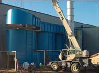
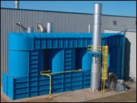
In addition to adding another chamber, Salem Savard extended the system’s oxidation chamber, added another burner placed over the addition, modified the fan wheel for the additional capacity and connected new exhaust ducts.
Because the inlet velocity at the regenerative beds is lower, due to larger cross sectional area per cfm, the expected pressure drop would be 10-11 inch w.c., just as in the structured packing option. Comparative energy costs are essentially a non-issue.
Flex-N-Gate also discovered that installation schedule constraints were lower than might have been expected. Most construction work was able to be done while the existing RTO was in operation, requiring shut down only for the final tie-in to the RTO and re-start and adjustments.


