A Novel, Structurally Colored Coating for Aluminum Alloys
A recent development based on porous anodized aluminum (PAA) and metal nanowire deposits is presented here, which may become a competitive alternative to paint and organic coatings. By controlling the conditions for anodizing and metal electrodeposition, coatings in a wide spectrum of colors can be produced, including greys, black, blues, purples and greens.
#nasf
by
Ian Mardon, Fengyan Hou and Chris Goode*
Featured Content
Cirrus Materials Science Ltd
Auckland, New Zealand
Editor’s Note: A printable pdf of this paper can be accessed and printed HERE.
ABSTRACT
Current approaches to coat aluminum surfaces that use paints and organic coatings to protect them from corrosion and provide an aesthetic finish, are also energy intensive and involve high emissions of VOCs. The use of these coatings is becoming increasingly restricted by global efforts towards more environmentally sustainable surface finishing technologies. A recent development based on porous anodized aluminum (PAA) and metal nanowire deposits is presented here, which may become a competitive alternative to paint and organic coatings. Anodizing and electrodeposition do not emit VOCs and are less energy intensive. By controlling the conditions for anodizing and metal electrodeposition, coatings in a wide spectrum of colors can be produced, including greys, black, blues, purples and greens. Characterization of the coating morphologies and corresponding colors agrees with simulated results based on the Fresnel equations and Bruggeman Mixed Media Approximations.
1. Introduction
Aluminum alloys are a common choice of material in applications, such as in architecture, automotive and aerospace, due to their desirable strength-to-weight ratio and their corrosion resistant oxide layers. Previously, various combinations of anodized surfaces and deposited metals had been used to create colored surfaces on light metal substrates,1 mainly through electrolytic coloring of aluminum alloys. These approaches had typically adopted sulfuric acid anodizing with AC electrolysis of metal salts, resulting in color generation that is purely dependent on light interference behavior within the anodizing pores.
2. Cirrus Hybrid™ Process Development
Cirrus Hybrid™ is a patented technology that combines anodized light metal surfaces with functional metal and/or polymer materials electrodeposited deposited in the anodizing pores. The hybrid process overview is shown in Fig. 1. In the first step, an aluminum part is subject to proprietary, principally phosphoric acid anodizing (PAA). This is followed by a controlled metal deposition where the metal grows from the bottom of and seals the pores. Advantageously, one of several functional coatings may be deposited which strongly interlocks with the pore structure and completes the coating system.

Figure 1 - Hybrid process overview.
In this article, a modified Cirrus Hybrid™ coating is presented, where nickel nanowires are deposited into the PAA structure. This combination results in a colored coating, where the optical properties are developed from the coating morphology. Figure 2 shows the modified structure of the Hybrid™ colored surface. Here, the anodizing and initial metal pore filling (1 and 2 of Fig. 2) are similar to the standard hybrid process. However, the functional layer is replaced with an air gap and seal (3 and 4 of Fig. 2).
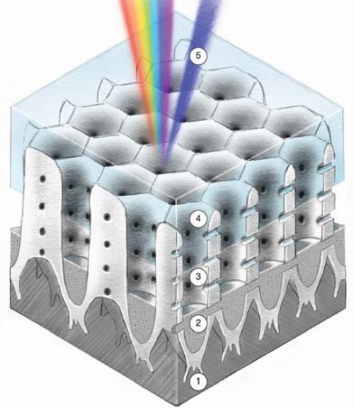
Figure 2 - Colored hybrid surface.
The Cirrus Hybrid™ Color technology has evolved over three generations with increasing understanding and control over the process. Initially discovered in 2017 as an offshoot of the hybrid coating development, only silvers, greys and blacks were achievable, as shown in Fig. 3 (Generation 1).
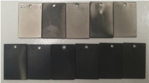
Figure 3 - Generation 1 colored surfaces.
Generation 2 developed from a systematic study and characterization of the light absorption mechanisms of the hybrid structure. The relationship between the coating gloss and substrate roughness was also developed. This allowed gloss, satin and matte black surfaces to be repeatably produced, as in Fig. 4.
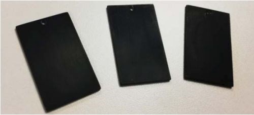
Figure 4 - Generation 2 colored surfaces.
Building on the learnings from Generation 2, Cirrus researchers initially uncovered a relationship between anodizing voltage, barrier layer thickness and color to provide a wider range of colored surfaces. They then investigated the use of pulse plating to deposit sub-micron scale, uniform metal nanorods in the pores, which minimized absorption, and created vivid colored surfaces of Generation 3, such as that shown in Fig. 5.
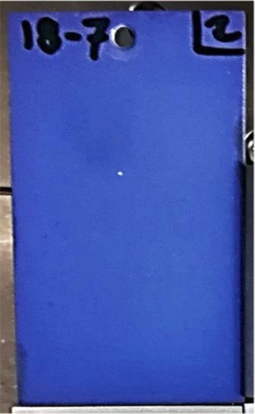
Figure 5 - A vivid blue developed using the Generation 3 process.
Here, we report both a novel anodizing and metallization process with the ability to produce a full spectrum of colored surfaces and a mathematical model of the color generation mechanism. Modelling of the coating was performed using the Fresnel equations and Bruggeman Mixed Media Approximation, supported by measurements of the coating morphology from SEM imagery. Simulations and measurements of the coating colors show good agreement. Furthermore, these results demonstrated that the critical color determinant is the barrier layer thickness. PAA allows very thick barrier layers to be developed.2 However, to support thick barrier layers without the associated pore widening, which would weaken the coating and produce an easily corroded surface, the anodizing bath must be carefully controlled.3,4 Modelling and experimentation also suggested that the metal/air interface above the deposited nanowires was vital for retaining the coating color; thus, to produce a surface that is industrially viable, very specific seal characteristics are required.
Reported here are two interesting technologies to produce a seal. While hybrid colored surfaces are naturally scratch-resistant, appropriate sealing solutions provided the long-lasting surface and allowed the Cirrus Hybrid™ technology to be a candidate to replace paint in lightweight automotive and aerospace applications. Currently, these applications relied on organic-based colored coatings, which are energy intensive, produce environmentally damaging toxic wastes and other by-products, such as Volatile Organic Compounds (VOCs). The authors posited that the low energy hybrid color process would decrease carbon and VOC emissions, provide cost savings, and improve end-of-life recycling options.
3. Experimental
3.1 Substrate preparation
Aluminum Al-6061 alloy sheet, 2-mm thick, was laser cut into 3-cm × 5-cm coupons, which were polished to various finishes, degreased in Metaclean ZX-E solution, followed by chemical activation of the surface using a Probright acid etch. A 50% nitric acid dip was used for several minutes to de-smut the substrates prior to anodizing.
3.2 Application of Cirrus Hybrid™ color coatings
Multiple samples were prepared for each of the chosen parameters to allow for independent testing of various coating properties. A proprietary, phosphoric acid-based anodizing bath was used to produce an anodized layer of between 5 and 10 microns on the aluminum coupons. Polyethylene glycol was added to the bath to allow for higher voltage anodizing. The coupons were anodized at 60, 70, 80 and 90 volts, to evaluate the effect of anodizing voltage on the resultant coating color. The anodizing temperature was maintained at room temperature (27±1℃) by using a recirculating cooler, together with air agitation of the anodizing solution.
Anodized samples were rinsed in deionized water and immediately submerged into the electroplating bath for a period to allow the solution to diffuse into the porous surface. Various commercial nickel-plating baths were tried, including semi-bright nickel, bright nickel, zinc-nickel, etc., with the color produced being substantially independent of the bath selection. An initial very low current density was applied to foster nucleation of electrodeposited metal at the base of the pores. The current density was then increased to form the nanowires, only partially filling the porous surface. The colored surfaces were then rinsed with deionized water, and dried using compressed air. Direct and Pulse Current (DC and PC) electrodepositions were compared to evaluate their effect on the color uniformity.
3.3 Sealing
Initial corrosion testing demonstrated that the coatings after electrodeposition lacked corrosion resistance. The close contact between the electrodeposited nickel and the aluminum allowed for galvanic corrosion. UV-initiated and electrolytically prepared polymer seals were applied to improve corrosion resistance.
3.4 Testing coating performance
Sealed coatings, together with unsealed control samples, were subjected to neutral salt spray corrosion testing, as per ASTM B117. The samples were observed every 12 hours, and the corrosion points were counted. The number of corrosion points over time was used as a metric to analyze the corrosion performance.
Duplicate samples were subjected to the mechanical testing methods, including wear and scratch testing, to evaluate the performance of the coatings. The measurements from these mechanical tests were recorded and compiled to evaluate the potential performance of these coatings for commercial applications.
3.5 Evaluating coating morphology and color
Duplicate samples were imaged using SEM and optical microscopy. The resulting images were used to measure the anodizing characteristics including pore diameter, interpore spacing, side pore diameter and side pore interpore spacing. The overall coating thicknesses and metal fill were also assessed. The coating was simulated as a stack of layers with alternating porosity, where the high porosity layers were the diameter of the side pores, and the low porosity layers were the interpore spacing of the side pores. The calculated refractive index for the alumina-nickel and alumina-air from Bruggeman mixed media approximation then allowed for evaluation, using the Fresnel equations, of simulated reflectance spectra. These spectra were integrated with CIE** color matching functions to produce an RGB value associated with a coating morphology.
Samples were also photographed in a lightbox, and the images processed in Imagej to determine both the color (in the CIE-Lab and -RGB color coordinate systems), as well as the color variance across the sample surface, measured by ΔE:
(1)
Color difference between samples and their simulated counterparts were also evaluated using equation (1), except the difference between CIE-Lab color coordinates was used in place of standard deviations.
4. Results and discussion
4.1 SEM and optical Microscopy
Figure 6 shows an SEM of a hybrid film that has been bent to expose the metal nano rods. Here, the regular arrangement of vertical pores may be clearly observed. Figure 7 depicts the metal nanorods in the coating. This deposit was created using direct current, and uneven pore filling5 resulting from uneven nucleation across the pores. As will be seen, differing nanowire lengths produce a slight spread in the resulting color spectrum and resulted in muddy colors. Pulse deposition develops more uniform nanowire length and brighter colors. The side pores which periodically connect the main pores with the oxide layer may be observed in Fig. 7. In this example, at their opening to the main pores these side pores are approximately 150 nm from center-to-center and are 70 nm in diameter.
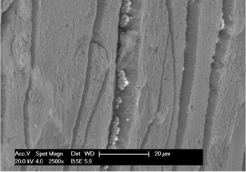
Figure 6 - The open, alumina anodizing is dull compared to the high conductivity nickel, shown as bright deposits in the oxide.
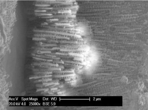
Figure 7 - High magnification of the center of Fig. 6.
Figure 7 further shows the nanowire pore filling where the interlinked nanowires are of periodically varying lengths due to the use of DC electrodeposition. The optical model of the coating system modelled the periodic porosity, which was found to be critical in producing a specific color.
Figure 8 shows a larger scale view of a ~4-micron grey coating, identifying the elements of the hybrid system. This early sample was created using DC plating with nanowires far longer than required to achieve the color.
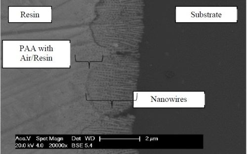
Figure 8 - SEM image of a metallographic cross section.
Figure 9 shows the relationship between pore and cell average diameters and the anodizing voltage. The depicted linear trend is typical of acid bath anodizing. It is important to note that the cell diameter increases slightly faster than the pore diameter, meaning the porosity of the coating decreases with increasing anodizing voltage. This divergence would imply an increase in toughness with voltage with a corresponding improvement in certain mechanical properties. Evaluating these are however, outside the scope of this article. The decrease in porosity also means a lower volume fraction of nickel in the alumina matrix; nickel is a very glossy material in the visible spectrum, so less nickel will mean less absorbance, as compared to the dielectric alumina.
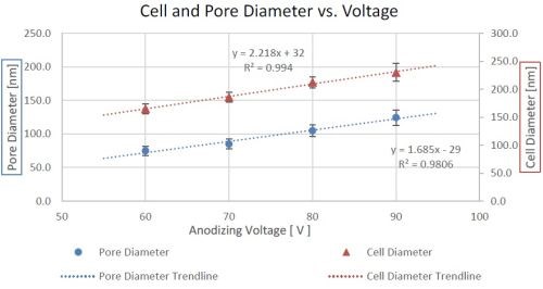
Figure 9 - Trends of pore and cell diameters vs. anodizing voltage.
4.2 Initial modelling of sample morphology
Through use of the Bruggeman Mixed Media approximation6 and the Fresnel Equations,5 the reflection spectra of simplified coating models were simulated. The detailed results, which will be available in a future publication, show good agreement between the simulation results and the measurements of prepared samples. These results demonstrate that the color generation technology is a unique result of morphology associated Cirrus Hybrid™ coloring technology.

Figure 10 - Simulation results from measurements of coating morphology, Bruggeman mixed media approximation and the Fresnel equations.
Figure 10 shows the results of the optical modeling of the coating morphology and composition. The CIE color matching functions are designed to produce color coordinates for reflection spectra not considering absorption losses. On the left of Figure 10, the brown color corresponds to black on real samples, as the resonant peak in the reflection spectra is outside the visible spectrum. The colors observed, left-to-right, show that black moves towards dark blue, lightening in color with a section of light blue, before moving into yellows, greens and reds. The minimal effect of the nickel fill can be deduced from the consistency of color as the nickel fill increases for a given anodizing voltage.
4.3 Sample color analysis
The prepared coatings were imaged, and the color coordinates and color variation (ΔE) were evaluated, as described in Section 3.5. CIE defines a ΔE of 2.3 to be the “Just Noticeable Difference,”7 and many paints are designed to produce coatings with ΔE less than 1.
Table 1 - RGB values and colors, as well as internal color variation for samples at 60V to 160V.

The observed color varied little as the nickel electrodeposition time (and thickness) increased for samples anodized at the same voltage. Samples anodized at the same temperature were seen to shift from black to dark blue, to blue, as the anodizing voltage increased as shown in Table 1. Table 1 also shows three samples anodized at 60V, with increasing anodizing temperatures. The increased temperature favors electrolyte dissolution of the anodized oxide, resulting in higher porosity, and thus darker colors due to the presence of more light absorbing nickel in the coating.
There is good agreement between the simulation results (Section 4.2) and the real world colors, and thus we may conclude that the thickness of the barrier layer, with the filtering properties of the air-alumina-mixed layers above, gives rise to the coating color.
4.4 Corrosion performance of coating
Samples were tested for corrosion resistance, following the ASTM B117 procedure. Unsealed coatings typically survived no longer than 48 hours before corrosion points occurred, which indicated the requirement for a sealing layer to protect the underlying colored coating. Galvanic corrosion between the nickel and the aluminum substrate required that the sealing material eliminate contact between the nickel deposits and corrosive media while maintaining color.
Table 2 - Corrosion resistance as well as the color change between unsealed and sealed samples.

Table 2 shows the effect of two polymer seals on the corrosion resistance, where both polymer seals provided approximately an 8-fold improvement. Both seals also significantly changed the perceived color of the coating. The electropolymerized seal layer, whilst only ~0.2 μm thick, provided a uniform barrier layer between the corrosive media, the underlying nanorod and substrate. This seal, as deposited, was not optically clear, so the color of the coating was masked by its dark brown/black aspect. The UV polymer also provided an effective barrier layer, with corrosion points only observed at the edges of the samples where the monomer had not been applied. Whilst the transparent UV polymer maintained the coating color better, there was still a change in color. Adding the polymer seals to the existing model demonstrated that the seal induced color changes were principally due to the change in refractive index of the unfilled pores. This result suggested that an air layer is required in the pores to preserve the color.
Modifying the model to include an air pocket of variable dimension together with low refractive index polymers seal suggested that 1-2 microns of air are sufficient to retain the coating color. Development of polymer nanoparticles (PNPs) allowed the pore openings to be plugged, holding back infiltration of UV monomer. PMMA nanoparticles are optically clear and may be tuned in diameter to match the pore size.8 By flowing the PMMA NP over the surface and drying >95% of the pores are effectively sealed leaving an air gap between the nickel layer and the surface of the anodized film. Deposition and polymerization of a subsequent UV monomer effectively sealed the surface, protecting the substrate, while retaining the color and providing outstanding corrosion protection and surface toughness. This sealing method did not change the original color but does provide added glossiness.
5. Conclusion
The development of this novel color coating has allowed for the integration of electrodeposition and proprietary anodizing to produce coatings in black, shades of grey, and various shades of blue on aluminum alloys. Further increases in anodizing voltage will expand the color range to incorporate the full visible spectrum. The colored surface, which is naturally scratch- and UV fade-resistant, with appropriate seal will offer a long-life colored surface. Making use of this robust, alternative coating technology, in combination with an appropriate sealing system, may offer a low energy consumption and low VOC replacement for paint. The ability to tune the anodized layer morphology allows for fine grained control over the resultant color.
6. References
1. K.T. Sato and I. Yasuhiko, “Observation of barrier layer during ac electrolytic coloring of anodized aluminum,” Electrochim. Acta, 26 (9), 1299-1302 (1981).
2. A. Eftekhari, Nanostructured Materials in Electrochemistry, John Wiley & Sons, 2008; pp 14-18.
3. J. Faucheu, et al., “Structural Colors of Nanoporous Anodic Alumina: Overview of Recent Advances and Case Study in Elaboration, Characterization, Photometry and Modelling,” Current Nanoscience, 11 (3), 317-325 (2015).
4. L. Yisen, et al., “Structural coloring of aluminum,” Electrochem. Comms., 11 (12), 1336-1339 (2011).
5. A. Ruiz-Clavijo, et al., “Engineering a full gamut of structural colors in all-dielectric mesoporous network metamaterials,” ACS Photonics 2018, 5 (6), 2120-2128 (2018).
6. H.A. Macleod, Thin-Film Optical Filters: Series in Optics and Optoelectronics, 5th Edition, CRC Press Ltd, 2017; pp. 13-103.
7. CIE Technical Committee 1-48, CIE Technical Report: Colorimetry 3rd Edition, 2004 International Commission on Illumination (CIE).
8. B.L. Kamras, et al., “Formula-Driven, Size-Tunable Synthesis of PMMA Nanoparticles by Varying Surfactant Concentration,” Materials 2020, 13, 1384 (2020).
About the authors

Ian Mardon is a Materials Research Engineer, who has been with Cirrus Materials Science for nearly two years. He graduated from the University of Auckland with a Bachelor of Engineering (Honors) in Chemical & Materials Engineering. Ian has co-authored academic papers and contributed to the Cirrus patent disclosures.

Dr. Fengyan Hou is a Senior Materials Scientist at Cirrus Materials Science. Previously he was Chief Scientist of the Coating Branch at Shanghai Baoshan Steel. He is an expert on corrosion and coating technology, and now works on the development of new functional surface coatings on steel, aluminum, magnesium and copper alloys. He uses techniques such as electrodeposition, anodizing, electropolishing and electroless to develop high performance coatings with superior mechanical, electrical, optical and corrosion properties.

Chris Goode is a founder and Chief Technical Officer at Cirrus Materials Science Ltd., in Auckland, New Zealand. Chris holds an honors degree in engineering from the University of Western Australia. He holds over 30 patents and has extensive experience in multiple fields of engineering including telecommunications robotics and chemical engineering.
* Corresponding Author:
Chris Goode, CTO
Cirrus Materials Science Limited
C/- 203/16 Huron Street
Takapuna
Auckland, Auckland 0622 New Zealand
Phone: +64 21 248 8853
Mobile: +64 21 248 8853
E-Mail: chris.goode@cirrusmaterials.com
** Commission Internationale de l'éclairage, or in English, the International Commission on Illumination.
RELATED CONTENT
-
AES Research Project #41: Part 4: Adhesion Failure of Electrodeposited Coatings on Anodized Aluminum Alloys
An SEM study of peel-test adhesion specimens from plated coatings on anodized aluminum shows that failure can be categorized in three different modes: (1) specimens exhibiting poor adhesion strength, which fail at the anodic film/coating interface; (2) specimens with good adhesion strength, which fail by local fracture of the anodic film and (3) specimens with excellent adhesion strength , which fail when the applied load is greater than the strength of the alloy substrate. The effect of anodizing parameters and alloy composition on peel test failure are discussed.
-
The Adhesion of Electrodeposits to Plastics
The 1966 Carl E. Huessner Gold Medal Award was given to Dr. Edward Saubestre and co-workers for Best Paper appearing in Plating in 1965, and their paper is republished here in a series on the AES/AESF/NASF Best Paper Awards. This paper is a comprehensive treatise on the Jacquet peel test, a primary test method for determining adhesion on plated plastics.
-
Nanostructure of the Anodic and Nanomaterials Sol-Gel Based Materials Application: Advances in Surface Engineering
Porous alumina can be fabricated electrochemically through anodic oxidation of aluminum. This paper reviews sol-gel chemistry and applications, which also offers unusual nanoporous microstructures. The ability to control pore chemistry at different scales and geometries, provides excellent bioactivity, enabling the entrapment of biologically active molecules and their controllable release for therapeutic and medical applications.


