Advancements in Brush Plated Metal Matrix Composites
Finding safer, eco-friendly alternatives to hard chromium plating has been a main driver of brush electroplating research for the last decade.
#research #surfin
Editor’s Note: The following is a synopsis of a presentation given at NASF SUR/FIN 2018, in Cleveland, Ohio on June 4, 2018 in Session 7, Aerospace and Defense I: Innovating Performance Advancements. A pdf of this brief can be accessed and printed HERE; the complete Powerpoint presentation is available by clicking HERE.
ABSTRACT: Finding safer, eco-friendly alternatives to hard chromium plating has been a main driver of brush electroplating research for the last decade. Brush plating is an electrodeposition technique that does not require the use of tanks and uses a brush to deliver solution to the cathodes. An alternative to chromium in the form of metal matrix composites (MMC) offers unique and superior characteristics to metal plating solutions, including hardness, wear resistance and oxidation protection. Processes have been developed and processing factors have been determined for MMC of cobalt chromium carbide, nickel tungsten carbide and nickel chromium carbide. These composite coatings were deposited using a range of current densities and brush materials to assess their impact on homogeneity and performance. This paper reviews the advancements and process improvements of cobalt chromium carbide and demonstrates the research and effectiveness of nickel tungsten carbide and nickel chromium carbide.
Featured Content
Selective / brush plating
Finding safer, eco-friendly alternatives to hard chromium plating has been a main driver of brush electroplating research for the last decade. Brush plating is a portable electrodeposition technique that does not require the use of tanks and uses a brush to deliver solution to the cathodes in localized areas. As shown in Fig. 1, an electrolyte containing metal ions is introduced between a positively charged anode and a negatively charged part / component.
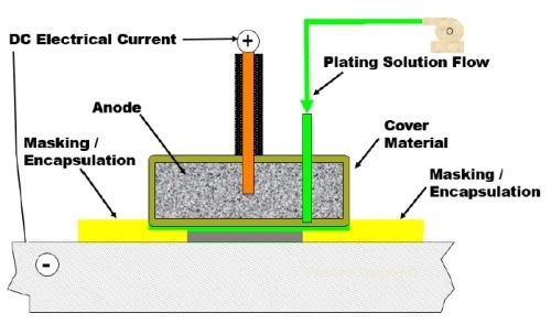
Figure 1 - Conceptual diagram for selective brush plating.
The brushing action disturbs the hydrodynamic boundary layer at the surface resulting in faster solution movement. The high solution velocity also replenishes metal ions at the surface more quickly. Accordingly, hydrogen gas bubbles are removed by the brushing action and high solution velocity. The brush action levels the deposit as it builds. Thus, selective plating allows for high efficiency and easily controllable application of the coating just where it is needed on the part / component.
Selective plating is not limited to metallic electrodeposits. Advances in technology at Sifco ASC have led to the selective deposition of metal matrix composite coatings, which opens these methods to advanced engineering coatings.
Metal matrix composite (MMC) coatings
A metal matrix composite (MMC) material is one with at least two constituent parts. Such deposits are quite common in tank plating, with non-conductive particles codeposited with an electrodeposited metal matrix. This is achieved by effectively and continually maintaining the suspended particles in the plating solution during electrolysis. Two phases are formed with the particle uniformly distributed throughout the coating.
Metal matrix coatings are desirable because of their properties, including structural reinforcement, wear resistance, friction coefficient and oxidation protection at high temperatures. The main driver today is to produce a safer, environmentally-friendly alternative to hard chromium. Applications are numerous, including bearing surfaces, tubes and nozzles carrying abrasive particles, as well as rotor blades and stator vanes.
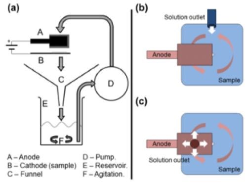
Figure 2- (a) MMC brush plating setup and comparison of (b) non-particulate and (c) particulate plating.
Figure 2 shows the design parameters necessary for MMC selective plating, including the basic elements in (a): the solution collection and circulation system, the rectifier, and the anode wrapped with material to provide electrode separation. The particle transportation is optimized to promote a steady solution flow through the system and the reservoir is agitated to keep the particles in suspension. In the current generation of Sifco ASC brush plating equipment, the tank design and fluid transport achieves about 90% particle suspension.
There are two solution flow geometries to consider. The flow configuration shown in Fig. 2(b), enters the plating zone from the side.
The design shown in Fig. 2(c) shows the flow to be directed through an orifice in the anode and allowed to impinge directly on the area to be plated and then outward from the center. In this way, a nominal particulate concentration is brought to where it is needed.
Three metal matrix composites are reported in this study. The work aimed to demonstrate the feasibility of depositing (a) nickel-tungsten carbide (Ni-WC), (b) nickel-chromium carbide (Ni-Cr3C2) and (c) cobalt chromium carbide (Co-Cr3C2) and evaluate the properties of each. Each was evaluated for selective plateability and the possibility of properties equal to or exceeding those of hard chromium.
Experimental
The substrates under study were prepared according to the following preplate cycle:
- Electroclean (10-15 V forward)
- Etch (9-10 V reverse)
- Desmut (12-15 V reverse)
- Nickel sulfate preplate (9-10 V forward; thickness 2 μm)
The brush plating conditions for the three MMCs are given in Table 1.
Table 1 - Plating conditions for the three composites studied.

Results and discussion
Effect of abrasive vs. non-abrasive brush pad
One other important variable was the material used in the brush pad. Abrasive (red and purple Scotchbrite™) and non-abrasive (white Scotchbrite™) materials have a significant effect on the deposit structure because of their interaction with the boundary layer. Figure 3 shows the combined effect of the pad material and current density on pure nickel brush plating. With a non-abrasive pad at the higher current density studied, a nodular deposit is produced.
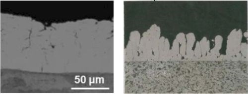
Figure 3 - Effect of brush pad material and current density of pure nickel brush plating: (L) abrasive red at 0.37 A/cm2; (R) non-abrasive white at 1.24 A/cm2.
Nickel-tungsten carbide (Ni-WC)
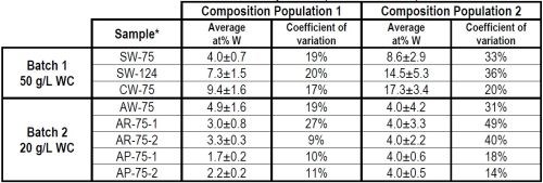
The feasibility of depositing a Ni-WC matrix was undertaken with the parameters for Ni-WC in Table 1. Selected results from the experimental matrix are shown in Table 2. A statistical analysis of the composition shows that for each population, the composition followed to distinct normal distributions. For all samples, Population 2 represents the areas where pooling occurs and demonstrates a higher composition and coefficient of variation. On the other hand, Population 1 had continuous flow demonstrating a lower composition and lower coefficient of variation. Referring to Batch 2, with air stirring and flow from the center of the brush, 20 g/L WC in solution and at 0.75 A/cm2, the abrasive brush pad materials (R and P) produce a more uniform WC particulate composition (as at% W) than the non-abrasive pads (W).
Table 2 - Effect of flow, current density and wrap material on composition.
|
*Sample nomenclature - XY-n-m: X = magnetically stirred set-up, solution flowing from side (S) or center (C), or air stir setup, solution flow from center (A). Y = Brush material, white (W), red (R), purple (P) n = Current density (0.75 or 1.24 A/cm2) m = Sample number |
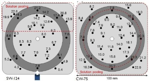
Figure 4 - Effect of flow regime on composition distribution: (L) Side flow; (R) center flow.
The flow regimen produced zones with significantly varying results. It is apparent that, as the solution travels away from the tube outlet, it tends to slow down, eventually stopping; as a result, it causes sedimentation (pooling) of the particles. As shown in Fig. 4-L, solution entry from the side (shown as the bottom) produced a continuous solution flow through the first 2/3 of the plating zone, beyond which solution pooling occurred at the end of the panel opposite to the solution entry. Entry from the center of the plating zone through the anode (Fig. 4-R), led to continuous flow outward from the center, with solution pooling around the entire perimeter. This pooling led to composition distribution problems.
In another comparison of abrasive versus non-abrasive brush materials, Fig. 5 indicates a slight improvement in surface morphology with the abrasive brush pad. Results for pure nickel on the other hand, show a significant improvement with the abrasive pad. Nonetheless, the Ni-WC morphology was smoother with smaller nodules as compared to pure nickel regardless of the brush pad material used.
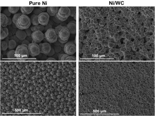
(a) White non-abrasive at 0.75 A/cm2.
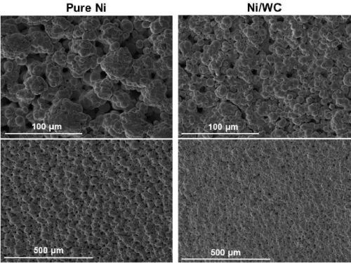
(b) Red abrasive at 0.75 A/cm2.
Figure 5 - Comparison of surface morphologies of pure Ni and Ni-WC composite deposits produced with non-abrasive and abrasive brush pad materials.
15,000-cycle Taber wear tests were performed. Localized coating failures were observed for all samples from Batch 1 with the higher plating solution concentration of 50 g/L WC. With the lower 20 g/L WC loading, no failures were observed. At 20 g/L WC and 75 A/cm2, the Taber Wear Index (TWI) ranged from 6.0 to 6.2, depending on the brush pad material used. These values have a wear resistance 2 to 4 times higher compared to TWI values of 14 to 20 for the original nickel matrix. The benchmark value for hard chromium is 3.2.
During the tests, coating failure was correlated with WC particulate composition (expressed as at% W). No adhesion failure was observed with deposits containing 2.6 to 10.2 at% W, above which mild failure was observed. Severe failure occurred at compositions above 21.3 at% W.
Nickel-chromium carbide (Ni-Cr3C2)
The feasibility of depositing a Ni-Cr3C2 matrix was undertaken with the corresponding parameters in Table 1, including variation in Cr3C2 particle size (1.7 and 6.0 μm) and brush materials. Evaluation was based on the overall impact of nickel-chromium carbides on composition, morphology and wear.
Figure 6 shows the results of the surface morphology studies, with all samples plated at a current density of 0.75 A/cm2 and compared with the results for pure nickel. Particle size had the largest impact on the overall composite deposit morphology. The morphology for deposits from the electrolytes containing 1.7 μm particles were the same for all brush materials. Further, the abrasive brush pad materials (red and purple) produced a smoother finish with smaller nodules. Surface roughness measurements were in good agreement with the SEM images.
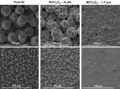
(a) White non-abrasive.
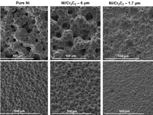
(b) Red abrasive.
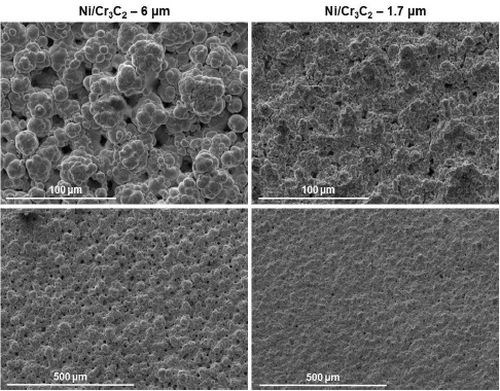
(c) Purple abrasive.
Figure 6 - Surface morphologies of Ni-Cr3C2 MMCs, comparing results for particle size and brush pad material: (a) white non-abrasive with pure nickel, and 6.0-μm and 1.7-μm particles in the electrolyte; (b) red abrasive with samples as in (a); (c) purple abrasive with 6.0-μm and 1.7-μm particles in the electrolyte.
The cross-sections of the deposits from the two particle sizes are shown in Fig. 7. Here, the solution containing 6.0-μm particles yields coarse, nearly nodular deposits versus the relatively smoother surface obtained with 1.7-μm particles.
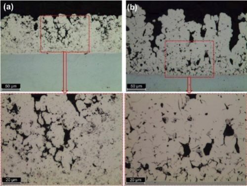
Figure 7 - Cross-section views of Ni-Cr3C2 composites from electrolytes containing (a) 1.7 μm and (b) 6.0 μm Cr3C2 particles.
Particle size and brush material both had an impact on the deposit composition, as shown in Table 3. The composites from electrolytes containing the 1.7-μm particles had significantly higher percentages of Cr3C2 (in terms of at% Cr), than the 6.0-μm particle size. The abrasive brush materials (red and purple) had higher Cr3C2 content than the non-abrasive material (white).
Flow regime data is also provided in Table 3. In general, the Cr3C2 content was greater in the case of continuous flow (Composition Population 1) versus the areas where solution pooling was observed (Population 2).
Table 3 - Effect of flow, Cr3C2 particle size and wrap material on composition.
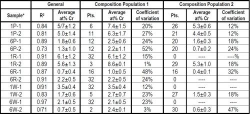
*Sample nomenclature - XY-n:
X = Cr3C2 particle size, 1.7 μm (1), 6.0 μm (6)
Y = Brush material, white (W), red (R), purple (P)
n = Sample number
The 15,000-cycle Taber Wear Index studies showed that the TWI values increased with particle size. For the 1.7-μm particles, the TWI ranged from 8.2 to 10.4 with the non-abrasive brush value higher than the two abrasive values (red>purple>white). For the 6.0-μm particles the TWI values ranged from 12.5 to 14.2 with no clear ranking between non-abrasive and abrasive brush materials (purple>white>red). Again, for comparison, these values compare to TWI values of 14-20 and 3.2 for pure nickel and the benchmark hard chromium, respectively. Wear performance correlates with increasing chromium content, a 1.7-μm particle size and the use of an abrasive brush wrap.
Cobalt-chromium carbide (Co-Cr3C2)
The feasibility of depositing a Co-Cr3C2 matrix was undertaken with the corresponding parameters in Table 1, including variation in 6.0-μm Cr3C2 particle concentration and current density. Evaluation was based on the overall impact of cobalt-chromium carbides on composition versus hardness, heat treatment and wear.
Table 4 - Hardness (VHN) and heat treatment response for Co-Cr3C2 composites.

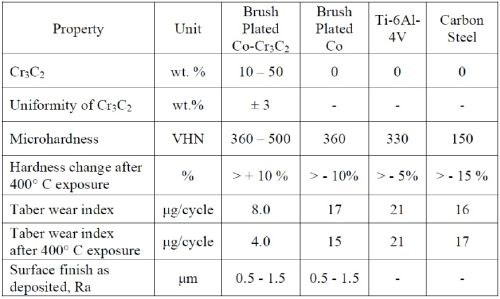
As deposited hardness and heat treatment response are summarized in Table 4. Values are given for the as-deposited sample and a one-hour heat treatment at the selected temperatures. Comparative values are 150, 330 and 360 VHN for carbon steel, Ti-6Al-4V and pure plated cobalt, respectively. The hardness increased up to 400°C, above which little or no change was noted. A slight decrease was noted with deposits containing lower amounts of Cr3C2.
To determine oxidation resistance a Co-Cr3C2-coated steel sample containing 15 wt% Cr3C2 was heated at 800°C for 30 hr in air. Only a slight surface discoloration was noted (Fig. 8).
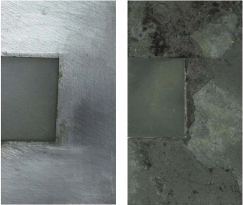
Figure 8 - Test of Co-Cr3C2 for oxidation resistance: (L)as-plated; (R) after 800°C for 30 hr in air.
Under Taber testing, an as-plated Co-Cr3C2 sample exhibited a 50% decrease in TWI over 20,000 cycles. Comparative Taber wear testing of Co-Cr3C2 and Ti-6Al-4V was performed on samples as-deposited and heat treated at 400°C.
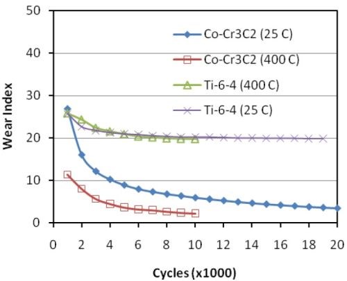
Figure 9 - TWI values for Co-Cr3C2 and Ti-6Al-4V with and without a 400°C heat treatment.
As shown in Fig. 9, heat treatment had no effect on the Ti-6Al-4V, while the TWI values Co-Cr3C2 decreased by 50% with or without heat treatment.
The key characteristics of Co-Cr3C2 are given in Table 5 and compared with Ti-6AL-4V and carbon steel.
Table 5 - Key characteristics of Co-Cr3C2.
Outlook
Brush plating of metal matrix composites shows considerable promise from these studies. Future work will be centered on further defining the key characteristics of Ni-WC and Ni-Cr3C2. This will include data on hardness, coefficient of friction, heating effects, etc. A major focus will be on the smaller 1-μm micron particle size and other abrasive wrap materials. Bath loading required for specific composition and wear properties is planned. Finally, other nickel-based electrolyte carriers should be explored.
About the Author
Danijela Milosevic-Popovich
Danijela Milosevic-Popovich, R&D Manager at Sifco ASC, joined the company in 2005. She is responsible for the design and execution of lab programs to develop and evaluate current products, new products and plating applications. She also provides the technical support and assistance to the quality, contract service and solutions manufacturing groups. She graduated from the State University of New York at Buffalo with a Bachelor of Science and Master of Engineering in chemical engineering. She then continued to earn her Master of Engineering Management from Ohio University. Prior to joining Sifco ASC, she worked in the semiconductor (IBM) and rubber industries.
*Compiled by Dr. James H. Lindsay, Technical Editor - NASF
** Corresponding author:
Danijela Milosevic-Popovich
R&D Manager
Sifco ASC
5708 E. Schaaf Road
Independence, Ohio 44131
Phone: (216) 524-0099
E-mail: dmilosevic@sifcoasc.com
RELATED CONTENT
-
Plating Q&A: Can you color stainless steel?
Our expert, Art Kushner, says yes, you can color stainless steel, but it is not a process that is typically performed in a plating shop. Read more about his answer.
-
Copper Plating on Aluminum and Aluminum Alloys
How can I plate copper on aluminum?
-
Smut and Desmutting
Question: I am new to this industry and have heard about smut and desmutting operations.


