
Share
Ultrafiltration (UF) membrane is manufactured by coating one side of a paper-thin, nonwoven substrate with a thin polymer layer. The polymer side is shiny and is where the paint makes contact with the filter. The other side is the permeate side, which is where water and other low molecular weight components (a.k.a. waters) appear after they pass through the small pores of the polymer layer. Once wound with a spacer sheet into an element, the polymer layer is fixed in place and protected by other layers to make it robust.
UF membrane works on a cross-flow principle. The desired waters transfer through the filter as the solution (ecoat paint) passes across the top layer. Ecoat paint is returned to the paint bath and permeate is diverted for use elsewhere.
Featured Content


Figure 1 - UF membrane works on a cross-flow principle.
Of note is a gel layer that forms on the polymer face as paint begins to flow across it. Waters can pass though small pores in the polymer. Some of the larger components in the paint are pulled over toward these pores, but are unable to pass though. At this point the ‘too large to pass through’ components have lost their velocity and find it hard to move out of the way. In a sense, they become ‘double parked’ on the face of the polymer. If there are just a couple of double parkers, the waters can still pass through. When the gel layer gets thick and viscous, the waters are greatly restricted from passing through and permeate production is much, much lower.
Operational Concerns
Over time, UF elements will produce less permeate. Low permeate flow is, by far, the most common complaint received from UF end users. Permeate is molecular material separated from paint solids because it can pass through a UF membrane’s small pores. A 7640-type UF element might have 17 lpm (~4.5 gpm) of permeate when new. Most end users consider permeate flow below 4 lpm (~1 gpm) to be too low and a signal that it is time to install a new UF element.
Low Paint Flow
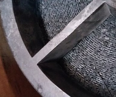
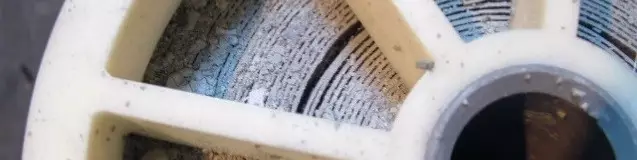
Figure 2a - Large particles can be seen on the inlet face of the UF element.
Low paint flow results in less active force that is needed to press the waters through the small pores of the UF membrane. Also, low paint flow generates less turbulence on the face of the membrane, which allows the gel layer to grow. Low paint flow is an important root cause in a majority of cases where the UF permeate is low or the element experiences short life.
Figure 2b - These particles can impede the paint flow, resulting in a short life of the UF element.
In Figure 2a and 2b, large particles can be seen on the inlet face of the UF element. The particles are impeding the paint flow. The result will be a loss of permeate flow and short life of the UF element. Proper prefiltering will prevent this from happening.
Also, in Figure 2b, the blocked inlet face has allowed the paint flow to make a new path by separating several leaves to make a larger opening for the paint to flow. This changes the orientation of the leaves and can result in a tear of the membrane, which will result in a leak.
Leaking UF Membrane/Paint in the Permeate
If the UF paint feed pump stops for some reason (for example, a power outage or maintenance work) it will need to be restarted. It is critical that the pump not be allowed to reach full rpms right after the pump motor is restarted. If this occurs, a ‘tsunami’ of paint inside the piping will expel air at a very high rate of speed and may cause damage to the UF Elements and the piping. (See Figure 3.)
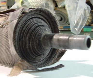
Figure 3 – Telescoped UF element
A soft start is an electrical device than can be set to allow 45-60 seconds to run the pump up to its full speed or, if there is no soft start, the operator has to take 60 seconds to fully open the UF system inlet valve. Similarly, a variable frequency drive (VFD) can be set up to safely ramp up the UF feed pump’s speed to avoid damage.
Leaking UF membrane can also result from excessive permeate pressure that creates a separation between the membrane and the nonwoven layer. Excessive pressure in permeate outflows can be caused by too-small manifolds, throttled valves or obstructions to the permeate flow.
Foam
If foam forms on the surface of the Ecoat bath or rinses, it (or its smaller components) will eventually pass through the pump and into the UF system. The foam components are small and go through a 25-micron rated filter bag. The portion of the foam bubble exposed to air will become air dried to some extent and will not pass through the UF membrane pores. Instead, it may linger on the surface of the UF membrane, acting as a barrier, much like placing plastic wrap over the holes of a colander.
Air bubbles in Permeate Flow Meter
Entrained air in paint can cause issues similar to what occurs with foam. Entrained air can partially cure paint with which it comes into contact. This air bubble particle may then linger on the gel layer, making it harder, thicker and more difficult for waters to pass through. Make sure there are no paint pump suction pipe leaks that could allow unwanted air to mix with the paint.
Root Causes
Below are some examples of items that may be at the core of operational issues that are presenting themselves.
Broken Fiberglass Housing
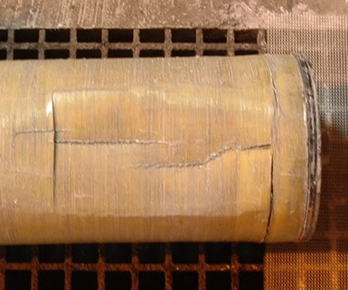
Figure 4 - Imploded fiberglass housing
Most spiral UF elements have a thin layer of fiberglass wound over the OD of the UF membrane spiral assembly. This is meant for protection during shipping and handling. On occasion, an end user has reported that the fiberglass has broken. Inspection showed the fiberglass to be cracked, with pieces pointing inward (for example, imploded). Figure 4 shows an imploded fiberglass housing. This may happen if the paint inlet pressure is much higher than the paint outlet pressure, causing a high delta pressure between the outside and inside of the element near the paint outlet side of the element.
When this occurs, the UF membrane is usually torn and paint will be visible in the permeate flow meter. The UF element will need to be replaced.
Missing/Misplaced Valve Handles
Valve handles can fall off and, in some cases, are not put back on properly. A valve handle installed backward or reversed may cause system damage and element failure.
“Plan the work. Work the plan.”
For proper operation of a UF system, a checklist should be required for each task an operator is expected to perform, especially if the operator is inexperienced.
Examples include:
- The inlet valve to the UF system should never be throttled. It needs to remain fully open. Only the UF system outlet valve should be throttled to achieve the proper flow of paint.
- The outlet valve of the UF system should never be closed completely because the paint flow channels will be blocked and will result in irreversible damage, in most cases.
- If there is no Soft Start or VFD on the UF feed pump, on startup the operator must manually open the valve to the UF system, taking a full 60 seconds to slowly open the valve and avoid damage to the equipment.
- Each valve needs its own valve tag that is referenced by a checklist. The valve should have a valve ID number and a color code: red = normally closed, green = normally open, or white = normally throttled.
New employees need training and orientation in the operation of the UF system. Many vendors (UF Element/UF Machine/Ecoat paint/system designer) provide training materials and assistance creating, updating and maintaining the UF Operator’s Manual and checklists. Daily log sheets are critical to understanding trends over time and should be part of all operator’s daily work schedules.
Prefilter
When compared to other UF membrane types, a drawback of spiral-wound UF elements is the need to prefilter incoming ecoat paint to keep large particles from blocking narrow paint flow channels. The most popular type of prefilter is a #2 filter 25 micron bag with a plastic collar.
Cleaning and the Gel Layer
As discussed in the membrane design portion, a gel layer forms on the polymer face of the membrane as paint begins to flow across it. It may be possible to perform a chemical cleaning. However, experience has shown it is very difficult to recover once the gel layer has become thick and viscous.
About the Author
Frederick Hess is CEO of UFS Corporation in Valparaiso, Indiana. Visit https://www.ufsc.com/
RELATED CONTENT
-
What is Electrocoating?
E-coat can produce uniform finishes with excellent coverage and outstanding corrosion resistance.
-
Measuring the Surface Area of Fasteners
How do you measure the surface area of a threaded fastener? How much coating would you put on it? How thick of a coating? What about non-threaded fasteners? The U.S. Department of Agriculture’s Forest Service, of all people, may have come up with the solution for those pondering how to coat sometimes-difficult small pieces using computer imaging and software to compute the area.
-
Coatings Drive Electric Vehicles Further
Electric vehicle batteries depend on coatings to maintain optimal temperatures, reduce the risk of fire damage and electrical interference, and more.


