Electrodeposition of Ni-Fe-Mo-W Alloys - 11th-12th Quarter Report
11th-12th Quarterly Report - AESF Research Project #R-117. This NASF-AESF Foundation research project report covers the 11th and 12th quarters of project work (July-December 2015).
#research #nasf
by
Ahn Phong Tran and Prof. E.J. Podlaha-Murphy*
Featured Content
Northeastern University
Boston, Massachusetts, USA
Editor’s Note: This NASF-AESF Foundation research project report covers the 11th and 12th quarters of project work (July-December 2015). Progress on the previous quarters has been published in summary in the NASF Report in Products Finishing and in full at www.pfonline.com.** A printable PDF version is available by clicking HERE.
Introduction
Novel, electrodeposited Ni-Mo-W alloys were developed in our past work1 and continued in Quarterly Report #7,2 with variable composition, and with interest in tailoring properties. For example, small amounts of tungsten in a deposit can improve the deposit hardness, wear resistance and corrosion resistance, while molybdenum can also offer similarly improved corrosion resistance, but also imparts catalytic behavior of interest for generating clean hydrogen.3-5 From a fundamental point of view, combining both molybdenum and tungsten elements in a deposit helps to probe their unusual induced codeposition behavior. Molybdenum and tungsten alloy deposition behavior is characterized by the observation that in aqueous solutions molybdenum and tungsten ions cannot be fully reduced to a metallic state, but can be completely reduced in the presence of certain elements, such as nickel, and first reported by Brenner.6 Experimentally, the codeposition of different binary combinations of molybdenum and tungsten alloys with cobalt, nickel and iron has been widely examined in a variety of aqueous electrolytes. In many of these electrolytes, ammonium hydroxide is a key component to achieve high current efficiencies in excess of 60%, although with relatively low amounts of the reluctant metal (i.e., molybdenum or tungsten) in the deposit. Eliminating the amount of ammonia in the electrolyte can be used as a strategy to increase molybdenum7,8 and tungsten9 in deposits when codeposited with nickel, however, with an appreciable drop in current efficiency. The use of ammonium hydroxide in aqueous solutions can also yield aqueous ammonia depending on the pH, which can be problematic in a plating line, as the ammonia readily volatilizes, and can be oxidized at the anode,10 thus its concentration is not easy to maintain.
In our past work in electrodepositing Ni-Mo-W alloys, an ammonia-free electrolyte with excess boric acid was used and deposits, with a reflective, smooth aspect were produced. The current efficiency was fairly low, ~10%, and could be improved with elevated electrolyte temperature to 20-30%.2 Interestingly, even with equivalent amounts of molybdate and tungstate ions in the electrolyte, there was consistently more molybdenum in the deposit. In this report we take a closer look at comparing Ni-W, Ni-Mo and the ternary alloy Ni-Mo-W, with the use of rotating cylinder electrodes. The electrodes have a small recess to promote a uniform current distribution.
Experimental
Ni-W, Ni-Mo and Ni-Mo-alloys were electrodeposited onto copper cylinder electrodes at a rotation rate of 517 rpm. The ammonia-free electrolyte contained 0.375M sodium citrate, 1.0M boric acid, and was maintained at pH 7 at room temperature. Polarization data were collected using a three electrode cell with a saturated calomel reference electrode (SCE), a sweep rate of 10 mV/sec, and corrected for ohmic drop using impedance spectroscopy. Galvanostatic deposition for one hour was used to deposit films over a large range of cathodic current density (13-300 mA/cm2). The composition of the alloys was analyzed using x-ray fluorescence (XRF). The XRF results only reflect the heavy elements and lighter elements such as sodium, carbon and oxygen were not characterized. The weight of the cylinder electrodes was measured before and after each experiment. When present, sodium molybdate and tungstate had a concentration of 0.075M, while the amount of nickel sulfate was varied between values of 0.05M and 0.2M. Six different electrolyte conditions were examined: (a) elemental nickel (0.1M), (b) a binary alloy of nickel-tungsten with 0.1M nickel species, (c) a binary alloy of nickel-molybdenum with 0.1M nickel species, (d) a binary alloy of nickel-tungsten with 0.05M nickel species, (e) a binary alloy of nickel-molybdenum with 0.05M nickel species and (f) a ternary alloy nickel-tungsten-molybdenum with 0.1M nickel species.
Results and discussion
Figure 1 shows the polarization curves for the electrolytes used in depositing elemental nickel and the binary alloys of Ni-W and Ni-Mo (Fig. 1(a)) having the same electrolyte composition of nickel, and for the binary electrolytes having a lower amount of nickel species in the electrolyte (Fig. 1(b)) and when they are all combined in a ternary electrolyte, (Fig. 1(c)). All polarization curves see a sharp increase in the region between -1.3 and -1.4 VSCE. In this region, the deposition of metal or alloy occurs. There is little difference in the total polarization when the amount of nickels ions is changed.
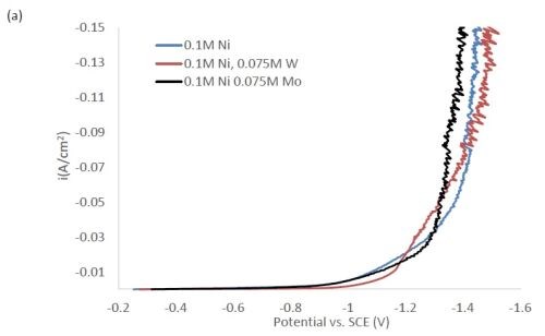
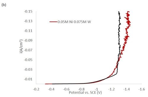
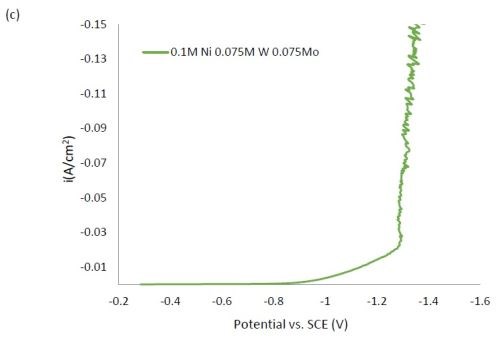
Figure 1 - Polarization curves with different concentrations of (a) binary electrolytes using 0.1M nickel are combined with electrolytes containing either 0.075M tungstate or molybdate, (b) binary electrolytes using 0.05M nickel with electrolytes containing either 0.075M tungstate or molybdate and (c) the ternary Ni-W-Mo system.
Figure 2 shows the wt% of (a) tungsten and (b) molybdenum in the binary and ternary alloys. At the same nickel electrolyte concentration, at lower current densities there is roughly the same amount of molybdenum as tungsten in Ni-Mo and Ni-W alloys, respectively. With an increase in current density the amount of tungsten decreases, but the molybdenum composition stays relatively constant. In the ternary alloy, there is more molybdenum in the deposit compared to tungsten, which is consistent with previous reports.1,2 A higher tungsten content is observed in the binary Ni-W electrolyte containing 0.05M nickel ions, the electrolyte with the highest ratio of tungstate to nickel ions. Similarly, the Ni-Mo electrolyte that contained 0.05M nickel ions contained the highest observed molybdenum content with an average of 80 wt% molybdenum. Even though lowering the amount of nickel resulted in higher amounts of either tungsten or molybdenum, it is not an expected result since both tungsten and molybdenum require the nickel to reduce. The very high amounts of tungsten and molybdenum are unfortunately codeposited at very low current efficiency.
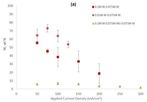
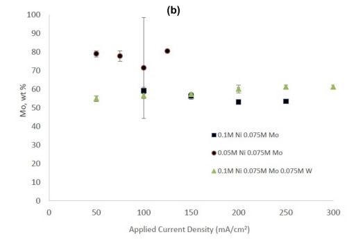
Figure 2 - (a) Tungsten composition in Ni-W and Ni-Mo-W deposits, and (b) molybdenum composition in Ni-Mo and Ni-Mo-W deposits produced at different applied current densities.
Figure 3 shows the current efficiency for elemental nickel. At low cathodic current density, in this electrolyte at room temperature, the current efficiency is ~40-45%. However, at this cathodic current density, when tungstate and molybdate are present no deposits occur. Only when the cathodic current density is significantly higher does the alloy form. In Fig. 3(b), the addition of molybdate ions to the electrolytes leads to significantly lower current efficiencies with values around 1-3%. While this is not a practical deposition condition, these results point to the interesting behavior of molybdate in the electrolyte compared to tungstate. The addition of tungsten ions in the solution leads to a decrease in current efficiency, but the effect is less pronounced in comparison to similar experiments containing molybdate ions. For all electrolytes, the efficiency dropped with increasing applied current density. The trend observed here correlates with previous studies reporting molybdenum is as a better hydrogen catalyst than tungsten in sputtered deposited films.11
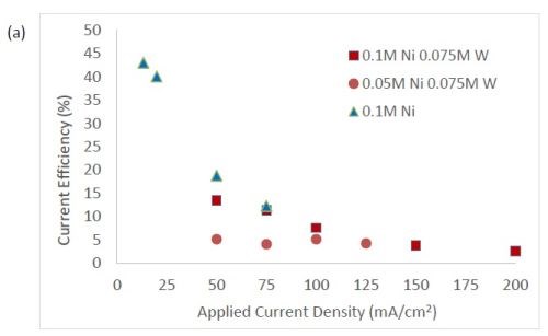
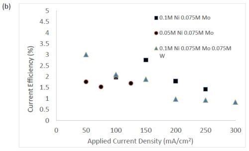
Figure 3 - Current efficiency in (a) electrolytes with tungstate ions, and (b) where molybdate is present.
The quantification of partial current density of the different alloys was made based on the assumption that the lighter elements composed a small fraction of the final alloy, and that steady state is achieved during deposition. The partial current densities of different alloys were calculated using Faraday’s law. The calculated partial current densities are presented in Fig. 4(a)-(d). The deposits were produced galvanostatically and the partial current densities were plotted as a function of the measured potential. The partial current density of nickel, Fig. 4(a), drops by an order of magnitude when 0.075M molybdate sulfate is added to any solution. The effect of adding tungsten is not as severe, but it also leads to a decrease in the partial current density of nickel. In the ternary systems studied, the addition of molybdenum and tungsten ions to a solution of nickel leads to a decrease of two orders of magnitude.
A possible mechanism governing the depositions of molybdenum and tungsten in conjunction with the iron group metals occurs through an absorption mechanism, involving complexed nickel-citrate species and assuming the formation of a mixed-metal intermediate that adsorbs onto the electrode surface.
NiCitˉ + 2eˉ ⇒ Ni (s) + Citˉ (1)
XO4-2 + NiCitˉ + 2H2O + 2eˉ ⇒ [NiCitXO2]adsˉ + 4OHˉ (2)
[NiCitXO2]adsˉ + 2H2O + 4eˉ ⇒ X(s) + NiCitˉ + 4OHˉ (3)
where X = W or Mo.
The model did not aim to capture all the complexities involved in the deposition such as citrate complexation, but gives a general understanding of the underlying principles regarding the deposition of Ni-Mo-W alloys. These observations are consistent with reaction conditions where molybdenum complexes occupy a large portion of the surface coverage, and in turn limit the amount of surface coverage available for the tungsten and nickel deposition reactions to occur. In Fig. 4(c), the partial current density of molybdenum is shown to vary little across different applied current densities. Also, the partial current densities of both molybdenum and tungsten were not significantly changed by their species concentrations in the electrolyte, suggesting a zero order kinetic control. A limiting reaction step of the reduction of molybdenum complex to a solid molybdenum deposit is believed to be the cause. We postulate that this results in a much higher absorption of Mo-intermediates than W-intermediates. This is also consistent with the observation that when molybdenum and tungsten are codeposited with nickel there is more molybdenum.
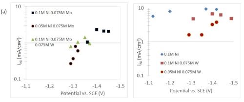
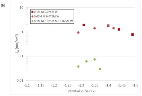
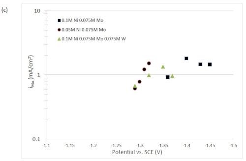
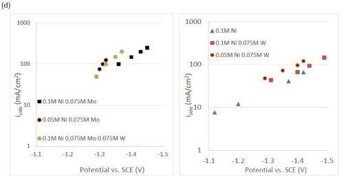
Figure 4 - Partial current density of (a) nickel, in the Ni-Mo and Ni-Mo-W electrolytes (left) and Ni-W and elemental nickel (right), (b) tungsten, (c) molybdenum and (d) side reaction in the Ni-Mo and Ni-Mo-W electrolytes (left) and Ni-W and elemental nickel (right).
The deposition of nickel without tungsten or molybdenum led to a non-uniform brownish surface. The appearance is dull, and the optical image in Fig. 5 shows a surface with little indication of micro-size cracks. Variations were indistinguishable between different applied current densities.
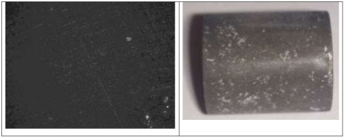
Figure 5 - Optical image and photograph of 0.1M nickel deposit using an applied current density of 50 mA/cm2.
In comparison, when 0.075M tungsten is codeposited with 0.1M nickel, a uniform and highly shiny surface is deposited (Fig. 6(a)). Some cracks are perceptible on the surface of this deposit. Of note, this sample exhibited a shiny, gray finish. When the amount of nickel is decreased by a factor of two, the resulting alloy still has a smooth surface but loses some of its shiny aspect. When the same comparison is done with 0.075M molybdenum, the electrolyte containing only 0.05M nickel was seen to be shinier (Fig. 7), even at very high current densities. The molybdenum-containing alloys exhibit no major perceptible crack on the surface. Different applied current densities did not lead to major changes on the deposit surfaces.
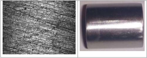
Figure 6 - Optical image and photograph of 0.1M nickel-0.075M tungsten deposit using an applied current density of 50 mA/cm2.

Figure 7 - Optical image and photograph of 0.1M nickel-0.075M molybdenum deposit using an applied current density of 200 mA/cm2.
The ternary alloy containing Ni-Mo-W (Fig. 8) was most shiny at applied current densities below 100 mA/cm2, and became progressively duller with increased applied current density. The surfaces had no perceptible cracks at this scale.
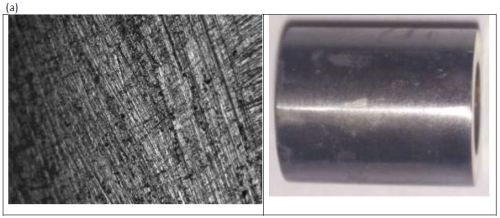
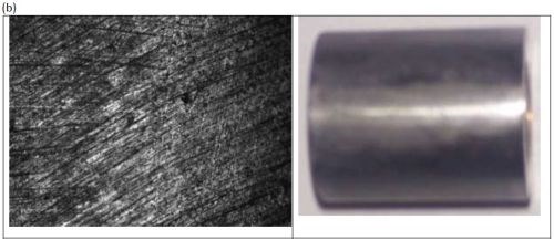
Figure 8 - Optical image and photograph of 0.1M nickel-0.075M molybdenum-0.075M tungsten deposit using an applied current density of (a) 100 mA/cm2 and (b) 250 mA/cm2.
Conclusions
A comparison of alloy composition, and partial current densities, were examined from Ni-Mo, Ni-W and a combined Ni-Mo-W electrolyte. The binary alloys resulted in very high quantities of the reluctant metal, molybdenum or tungsten, in the deposit over a wide range of current density. When molybdate ions are added to an electrolyte containing nickel ions resulting in Ni-Mo alloys, there is a large decrease in current efficiency due primarily to a drop in the nickel partial current densities at similar applied current density as well as to a significantly larger side reaction. The same effect is observed with the addition of tungstate ions to a similar nickel electrolyte, but these effects are shown to be smaller in magnitude. When tungstate and molybdate are electrodeposited concurrently in a nickel-containing electrolyte, there is an inhibition of the nickel and tungsten partial current densities by molybdenum. Additionally, the molybdenum partial current density and composition are maintained across a wide range of applied current density for the studied conditions. In the case of Ni-W alloys, the nickel reaction becomes more dominant at high applied current density. An absorbance mechanism for nickel, tungsten and molybdenum reactions explain the observed results well, and is believed to indicate a limiting step in the reduction molybdenum complex to molybdenum deposit. Uniform and shiny Ni-W, Ni-Mo and Ni-Mo-W can be deposited, despite the low current efficiency.
References
1. S. Sun, T. Bairchanya and E.J. Podlaha, J. Electrochem. Soc., 160 (10), D434-D440 (2013).
2. E.J. Podlaha-Murphy, A. Kola and Rui Wu, Products Finishing, 79 (7), 1-9 (2015).
3. H. Fukushima, et al., Transactions of the Japan Institute of Metals, 20 (7), 358-364 (1979).
4. W. Plieth, in Electrochemistry for Materials Science, Chapter 8, Elsevier (Amsterdam), 2008; pp. 231-262.
5. N. Tsyntsaru, et al., Surf. Eng. Appl. Electrochem., 48 (6), 491-520 (2012).
6. A. Brenner, Electrodeposition of Alloys, Academic Press, Inc., New York, NY (1963).
7. E.J. Podlaha and D. Landolt, J. Electrochem. Soc., 143 (3), 885-892 (1996).
8. S. Sun and E.J. Podlaha, J. Electrochem. Soc., 159 (2), D97-D102 (2012).
9. O. Younes and E. Gileadi, J. Electrochem. Soc., 149 (2), C100-C111 (2002).
10. L. A. Diaz, et al., Electrochim. Acta, 89, 413-421 (2013).
11. A. Kawashima, et al., Materials Science and Engineering: A, 226-228, 905-909 (1997).
Footnotes
*Corresponding author:
Prof. E.J. Podlaha-Murphy
Professor of Chemical Engineering
Northeastern University
Boston, Massachusetts 02115
Phone: (617) 373-3796
E-mail: e.podlaha-murphy@neu.edu
**Quarter 1 (January-March 2013): Summary: NASF Report in Products Finishing; NASF Surface Technology White Papers, 78 (1), 11-17 (October 2013); http://short.pfonline.com/NASF13Oct2.
Quarter 2 (April-June 2013): Summary: NASF Report in Products Finishing; NASF Surface Technology White Papers, 78 (2), 18-27 (November 2013); http://short.pfonline.com/NASF13Nov2.
Quarter 3 (July-September 2013): Summary: NASF Report in Products Finishing; NASF Surface Technology White Papers, 78 (4), 11-16 (January 2014); http://short.pfonline.com/NASF14Jan2.
Quarters 4-6 (October 2013 - June 2014): Summary: NASF Report in Products Finishing; NASF Surface Technology White Papers, 79 (2), 1-14 (November 2014); http://short.pfonline.com/NASF14Nov1.
Quarter 7 (July - September 2014): Summary: NASF Report in Products Finishing; NASF Surface Technology White Papers, 79 (7), 1-9 (April 2015); http://short.pfonline.com/NASF15Apr1.
Quarter 8 (October - December 2014): Summary: NASF Report in Products Finishing; NASF Surface Technology White Papers, 79 (10), 1-8 (July 2015); http://short.pfonline.com/NASF15Jul1.
Quarter 10 (April - June 2015): Summary: NASF Report in Products Finishing; NASF Surface Technology White Papers, 80 (7), 1-8 (April 2016); http://short.pfonline.com/NASF16Apr1.
About the authors:


RELATED CONTENT
-
Passivation Basics
What is commonly referred to as "passivating" on a shop floor is actually just enhancement of a naturally occurring process on most stainless steels.
-
White Bronze, Copper-Tin-Zinc Tri-metal: Expanding Applications and New Developments in a Changing Landscape
This paper deals with the renewed interest in applications for white bronze tri-metal (Cu-Sn-Zn alloy).
-
Troubleshooting Chromium Conversion Coatings on Aluminum
This paper provides processors with an extensive troubleshooting tool when conversion coating failures are encountered.


