
How to Apply the 720 Rule to Current Density Anodizing
What can you tell me about the 720 Rule as it applies to current density anodizing? Plating expert Sjon Westre, Ph.D., from Chemeon, answers this question.
#basics #racking
Share
- What can you tell me about the 720 Rule as it applies to current density anodizing?
A. We bring anodizers and manufacturers in from around the country to teach them the best practices for aluminum anodizing. During this class, we typically discuss the 720 Rule, along with current density anodizing. This rule is a very powerful tool for managers, estimators and planners, as well as anodizers, but we often find that our students are not entirely familiar with what it is, or what they can do with it.
The 720 Rule describes the relationship between the amount of current passed through an aluminum surface and the resultant anodic oxide thickness produced over time. It is known that 720 amp-minutes of current per square foot of load are required to produce one mil (0.001" or 25.4 microns) of anodic oxide (Westre 1997, 2017) (Westre 2000). Although the source of this relationship is not well documented, it has been suggested that the relationship is derived from the Ilkovic equation using the half-cell potential for aluminum (Runge-Marchese 1999).
Featured Content


At its most basic, the 720 Rule is a way to determine anodizing build rate, anodizing time or the current density of the anodizing load when the other two parameters are known.
Functionally, we express the relationship as Equation 1:
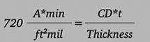
where “CD” is the current density in amps per square foot, “t” is the exposure time in minutes and the resulting thickness is in mils. We can rewrite Equation 1 to emphasize the relationships of interest:
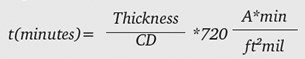
Equation 2 allows us to calculate that, to achieve a 1-mil oxide thickness at 24 amps per square foot (ASF), 30 minutes is required:
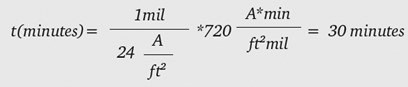
Table 1 shows the calculated time to 1 mil thickness for some common current densities:
| CURRENT DENSITY/ASF | TIME TO 1 MIL/MIN. |
| 12 | 60 |
| 18 | 40 |
| 24 | 30 |
| 30 | 24 |
| 40 | 18 |
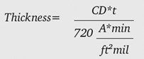
Simple rearrangement of Equation 2 shows that the amount of oxide generated at a particular current density as a function of time is Equation 3:
For anodizing in sulfuric acid electrolytes, this provides a very good estimate, regardless of alloy, electrolyte concentration and/or electrolyte temperature. In other words, it can be used to estimate the behavior of Type II anodizing on 6061 as well as Type III anodizing on 2024. It has been noted that perhaps the 720 Rule does not do as good of a job estimating 2024 thicknesses (Chesterfield 2008).
For precision work, we must compensate for the amount of oxide added during the ramp period. Equation 2 provides the anodizing rate at a constant current. In real-world situations, the rectifier is ramped from zero current to the target final current density. What happens during the initial ramp of the rectifier? It turns out this is quite simple for linear ramps. If the current is increasing over time “t” to a final current density “CD,” the amount of oxide generated during the ramp is:

For example, if we ramp our rectifier to 30 ASF over a five-minute period, the ramp contributes 0.104 mil to the total thickness. Equation 4 can be derived graphically by realizing that, during a ramp, the area under the line in a current density vs. time plot is a triangle whose area is 0.5 t*CD. Or, that the average current density during ramp is one-half the target final current density.
Another way to think about ramp compensation is that the amount of thickness formed during the ramp is half of what would be formed during the same amount of time under full current density. This allows us to simplify our thinking when trying to predict total process time to produce a desired coating thickness.
Most of the time, we are interested in how long it will take to form a coating of a certain thickness at a given current density. Equation 2 allows us to estimate the amount of time to produce a given oxide thickness at a particular current density. We can compensate for the amount of oxide formed during the ramp by looking at Equation 4, and realizing that during the ramp, the average current density is half the final current density.
Using Equation 2 or Table 1, we find that if we want to put on 1 mil of oxide at 30 ASF, it will take 24 minutes. So then we know that if we are doing MIL-SPEC anodizing to MIL-A-8625 and want to put on 2.0 mils, it will take 48 minutes anodizing at 30 ASF. What if we have a 10-minute ramp to the final current density? We can work successively through Equation 4 to deal with the ramp and then use Equation 2 to predict how long we have to run at full current density to achieve our target thickness of 2.0 mils.
From Equation 4:
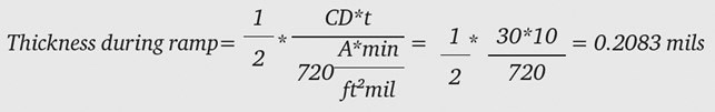
where the final current density is 30 ASF and the ramp time is 10 minutes. We want a final thickness of 2.0 mils, therefore our dwell time must produce: 2.0-0.2083 = 1.7917 mils. Using Equation 2, we calculate how long to anodize at 30 ASF to produce 1.7917 mils:
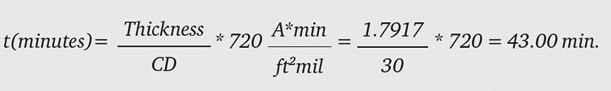
To summarize this example, a ramp of 10 minutes to 30 ASF with a dwell time of 43 minutes at 30 ASF will produce 2.0 mils of oxide to a good approximation.
If one is comfortable with Equation 2 and the fact that, during the ramp, the effective current density is half that during the dwell period (Equation 4), there is a simpler way to predict the amount of time required to ramp and dwell:
A. Use Equation 2 to predict the dwell time required to produce the coating thickness desired at the proposed current density.
B. Subtract half the ramp time from the prediction in Equation 2, and use that as the ramp compensated dwell time.
Mathematically, a 10-minute ramp from zero to full dwell current produces the same effect as a five-minute dwell at full current.
Here’s an example of a Type II anodize run worked problem: Say an anodizer wishes to run Type II and then dye the parts a deep black color. He or she might decide to run at 12 ASF to a thickness of 1 mil. For various reasons—part configuration, racking density and so on—the anodizer chooses a six-minute ramp. How long does the anodize need to dwell so that the final thickness is 1.0 mil?
Equation 2 or Table 1 shows us that at 12 ASF, 60 minutes are required. Our six-minute ramping from zero to full current is equivalent to three minutes at full current density. Therefore, 60 – 3 = 57 minutes of dwell at 12 ASF are required after the six-minute ramp in order to achieve a 1.0-mil oxide thickness.
Bibliography
Westre, S.G. 1997, 2017. Anodizing Best Practices and Troubleshooting. Training Manual, Minden: Chemeon Surface Technology.
Westre, S.G. 2000. Anodizer's Reference Manual. Training Manual, Minden: Chemeon Surface Technology.
Runge-Marchese, J.M. 1999. Electrochemical deposition of a composite polymer metal oxide. United States of America Patent 5,980,723. November 9.
Chesterfield, L. 2008. Calculating Anodizing Rate for Type II and Type III Coatings.
About the Author

Sjon Westre, Ph.D.
Sjon is vice president of technology at Chemeon Surface Technology. Visit chemeon.com.
RELATED CONTENT
-
Aluminum Surface Finishing Corrosion Causes and Troubleshooting
In this paper, a review of several process solutions, examining coolants, solvent cleaning, alkaline clean/etch and deoxidizing/desmutting, listing intended and unintended chemical reactions along with possible mechanisms that would favor corrosion formation.
-
The Powder Coating Process
Powder coating is one of the most durable finishes that can be applied to industrial manufactured products, and offers excellent corrosion protection and is very safe because of its lack of volatile organic compounds. To understand the powder coating process you should start with the fundamentals.
-
Polishing vs. Buffing: What's the Difference?
Is polishing the same as buffing? Mechanical finishing expert, Pat Wenino, explains the differences between the two processes.


