II. The Effects of Stopoffs and Thieves on the Distribution of Functional Chromium Electrodeposits
This is the second of three combined papers that received the AESF Gold Medal Award for Best Paper published in Plating & Surface Finishing in 1989. Stop-offs, thieves and guards are used to change the pattern of current flow and improve metal distribution. The effects may be planned or may occur unexpectedly, producing undesirable results.
#research #surfin
by
E.C. Knill
Featured Content
Retired from
M&T Chemicals, Inc., Research Laboratory, Rahway, New Jersey, USA
Editor’s Note: Originally published as E.C. Knill, Plating & Surface Finishing, 76 (2), 30-35 (1989), this is the second of three papers, all by Mr. Knill, which received the Gold Medal Award for Best Paper published in Plating & Surface Finishing in 1989, which was presented at SUR/FIN 1990 in Boston, Massachusetts. A printable PDF version is available by clicking HERE.
ABSTRACT
Stop-offs, thieves and guards are used to change the pattern of current flow and improve metal distribution. The effects may be planned or may occur unexpectedly, producing undesirable results.
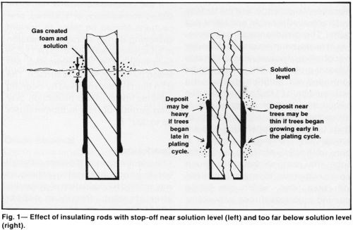
The primary effect of an insulating stop-off on metal distribution is an increase in thickness of the adjacent deposit. This is desirable when the stop-off is located just below the solution level, to prevent "shading" or thinning of the deposit at the solution level (Fig. 1, left). However, placing the stopped-off area more than 1.0 in. (2.5 cm) below the solution level and plating at more than 3 A/in.2 (40 A/dm2) in a high-ratio, low-concentration chromium bath at a temperature below 130°F (54°C) tends to cause excessive "treeing" (Fig. 1, right). The amount of distortion of thin or moderately thick deposits may not be objectionable on some parts but "trees," nodules or even minor thickness build-ups would not be acceptable for high quality finishes because their removal by special polishing or grinding adds unnecessary expense to the processing.
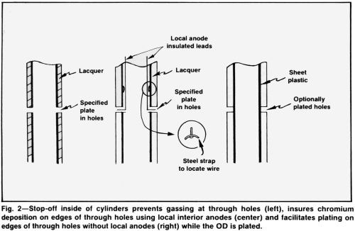
A stop-off is frequently used to prevent shading or "misplates" at the edges of holes. Stopping off the inside of hollow parts may make it possible to plate through holes while outside surfaces are plated (Fig. 2, left). At the same time, shading at both outside and inside edges of the holes is eliminated or greatly reduced.
Very small or deep through holes will require auxiliary anodes (Fig. 2, center), but much less current will be needed for plating them, in any case. For plating the outside of cylinders with through holes where plating is optional, a useful stop-off is a sheet of vinyl plastic pressed into the wet, freshly lacquered bore (Fig. 2, right).
All insulation must be fitted tightly. If it becomes loose during plating, distribution will be damaged. Low-current-density areas between the loosened insulation and the cathode not only rob current from the adjacent cathode area but also become sites for the generation of large amounts of hydrogen gas that escapes at critical cathode areas, which often causes "misplates."
Lacquers
Vinyl lacquers are excellent stop-offs when properly applied, but inadequate surface preparation or a viscous initial coating will cause poor adhesion. The proper surface preparation for dipping, brushing or spraying the lacquer is similar to that for plating. Surfaces should be cleaned before a stop-off is applied. If an acid treatment is required to remove oxides, surfaces must be neutralized by rinsing and redipping in the cleaning solution, which may be permitted to dry. Surfaces will dry quickly if rinsed when still warm.
A clean part may be lacquered immediately or wrapped in clean, kraft paper and stored. When stored in a dry atmosphere, no rusting will occur for several days. If longer protection is needed, cleaning solution should be allowed to dry on the surface before wrapping. Before further processing, redipping in hot cleaning solution and rinsing is essential.
Vapor degreasing is an excellent surface preparation for the application of any stop-off. After any cleaning operation, the surface to be lacquered should always be cleaned with clean lacquer thinner before the lacquer is applied.
The first prime coat should consist of a 50% solution of the lacquer in the recommended thinner. The film will dry quickly if the workpiece is still warm from a degreasing or cleaning operation. Four or five subsequent coats of lacquer should be applied at the viscosity supplied by the manufacturer. If thoroughly dried between each coat, the stop-off should withstand 24 hr or more of immersion in hot chromic acid solution. Forced drying in an oven provided with an approved exhaust system or a hand-held dryer will speed up the process.
The application of vinyl or paper tape immediately after the first full-strength coat also will shorten the preparation time. The wet coat tends to seal any pores or lap joints in the tape. The second coat of lacquer completes the sealing operation. The tape must be applied smoothly, free from gaps and wrinkles.
Removal of unwanted lacquer is a critical part of the operation. If dipping, over spray or brushing has allowed lacquer to spread over surfaces to be plated, lacquered-area edges should be trimmed with a knife and the plating surface lightly abraded with clean, aluminum oxide or silicon carbide paper. Thinner should not be applied to the plated area after this abrasion operation because any thinner touching the edge of the lacquer would smear a thin film of the lacquer over the surface to be plated. Although difficult to detect before plating, smeared areas appear streaky after plating.
Lacquer applied by dipping can be readily peeled off if applied over a thin film of dried alkaline cleaner or sodium bicarbonate solution. However, alkaline chemicals must be completely removed from adjacent areas to ensure a good bond during trimming operations.
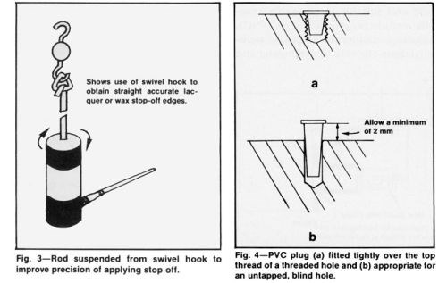
A rotated turntable or swiveled hook facilitates the application of lacquer or tape to cylindrical shapes (Fig. 3). In this case, trimming may not be necessary if the brush is carefully positioned at the edge of the stopped-off area.
Tape and wax
Tape without a lacquer-sealed edge is not recommended except for short-cycle commercial quality deposits. The adhesive backing on most of the available plastic tapes has a latex base that does not withstand the oxidizing effect of the chromic acid plating bath. Even after sealing with a vinyl lacquer, the value of the adhesive is negligible. Some expensive polyester tapes used for circuit boards resist chromic acid, but their use is limited to simple shapes because the tape is inflexible and cannot be applied to a surface that requires stretching of the tape.
Thin vinyl tape is preferred for high quality work but must be applied tightly without stretching it to its limit. The end of the tape can be sealed with lacquer applied to its underside or by heat sealing after softening with a flame and pressing it down to the layer below. A single layer of tape covered with a thin lacquer layer is satisfactory unless it must withstand a long immersion time in a bath maintained at a high temperature.
Fluorinated waxes used extensively many years ago have fallen out of favor because workers are exposed to unpleasant, potentially hazardous fumes. Butyrate-based waxes are useful for thin or moderately thick deposits up to 0.008 in. but do not form as tight a seal as the fluorinated waxes. When plating heavy deposits, chromium solution is prone to bleed under the wax, permitting chromium to deposit on the stopped-off area.
Permanent and reusable stop-offs
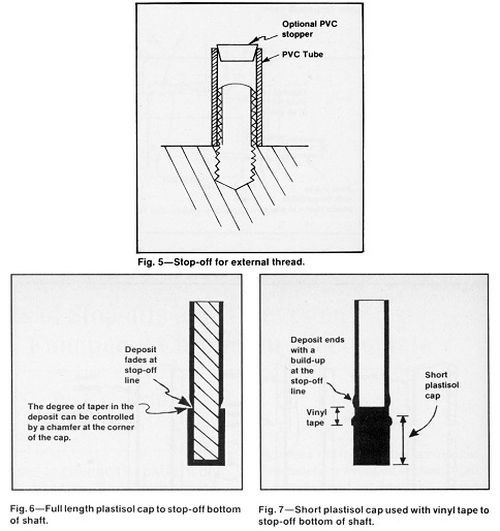
Plastic caps, plugs and standard geometrically shaped inserts can be purchased or ordered for regular production and are useful when carefully selected for the application. They are especially valuable for protecting projecting studs or tapped holes. Cone-shaped plugs should fit snugly in the hole and flush with the surface, completely covering the top thread (Fig. 4a). Such plugs are inexpensive and can be inserted rapidly. In unthreaded holes, the plugs should be allowed to protrude above the surface (Fig. 4b) to improve chromium thickness uniformity without a build up at edges.
Other prefabricated plastic shapes such as screws, pipe, tubing (Fig. 5), pipe fittings and laboratory stoppers are readily available from laboratory supply houses. A plastisol rack coating or paste-type plastisol patching material can be cast to make permanent stop-off shapes. To fabricate a reusable plastisol stop-off, coat the area to be masked without using a primer, after the part is preheated to about 400°F (204°C). When several coats are applied with intermediate cures at the temperature recommended by the supplier, the 1/8-to 1/4-in. (3 to 6 mm) thick form can be cooled and readily removed. Chamfering the edges will control the taper of the deposit above the edges (Fig. 6). If the form is trimmed short of the plating area, taping the edges will help hold the form in place and provide a sharp stop-off (Fig. 7).
Solid plugs can be made by filling a cavity with plastisol and heating long enough to cure the interior of the plug. An insert will help to hold the plug in place or facilitate its removal.
To avoid the necessity of machining a compression plug (Fig. 8), the mold can be plated with 0.004 to 0.008 in. (0.1 to 0.2 mm) of chromium to provide adequate clearance. This type of plug may be used to protect the inside surfaces of hollow cylinders and is most useful as an internal stop-off for small holes. A firm fit will keep the internal surface dry during a long plating cycle but the plug should not be tightened excessively or thin-walled tubes may be distorted.
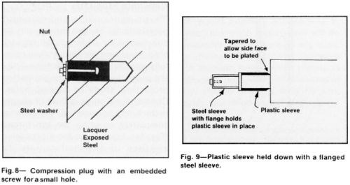
Reusable stop-off fixtures may be in the form of plastic sleeves or tubes that can be slipped over cylindrical parts or anodes. Fig. 9 shows an example of a plastic sleeve held in place with a flanged steel sleeve. A plastic shield can be attached to the work with a machine screw if the customer allows a hole to be drilled and tapped. The shield may be chamfered to allow chromium to cover the entire adjacent surface. Sheets of plastic that can be wrapped around a cylindrical shape may be used for short cycles.
Plastic materials resistant to chromic acid and suitable for reusable stop-offs include polyvinylchloride (PVC), polyvinyl dichloride (PVDC), poly-vinylidene chloride, polyethylene and polypropylene. More expensive fluorinated plastics may be justified for permanent fixtures having close dimensions that must be maintained for long periods. Most of these materials can be fabricated by welding but only PVC and PVDC can, be cemented readily with solvent or solvent-based cement or lacquer. Most of the others can be cemented with special adhesives and pretreatments.
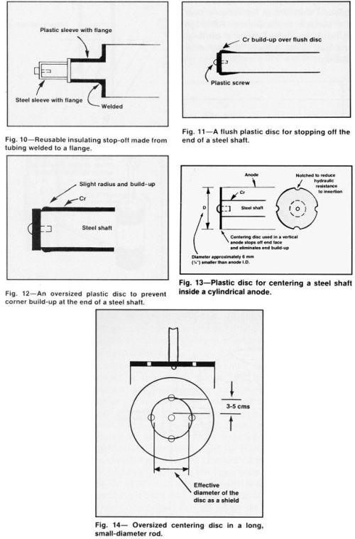
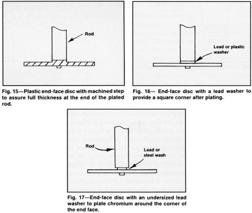
Figure 10 illustrates a permanent sleeve and flange fixture that stops off two adjacent surfaces. Discs that stop off an end face are common shields for distribution control. A heavy deposit tends to grow a ridge adjacent to a flush disc (Fig. 11), whereas a slightly larger flange will eliminate or minimize this effect (Fig. 12). Figure 13 shows an end-face disc that also centers the part in a cylindrical anode. A large disc may require perforations to provide an adequate supply of fresh solution inside the anode (Fig. 14). However, holes in the disc near the part being plated may introduce an undesirable flow pattern in the deposit.
Modifications of end-face discs useful for special purposes include: (a) the machined configuration shown in Fig. 15, which will provide a slight relief adjacent to the stop-off, (b) the insertion of a washer (Fig. 16) or an undersized washer (Fig. 17) when it is desirable for the chromium to plate around the corner for a short distance.
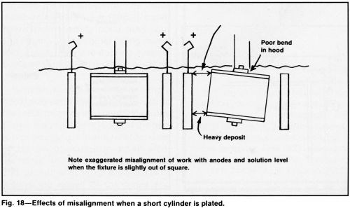
Long vertical cylinders plated at high current density can be raised up close to the solution surface to control build up at the top whereas short cylinders with a large diameter must be immersed to a deeper plane because a small error in leveling the part will create a major difference in thickness distribution (Fig. 18). Raising the current density causes more hydrogen evolution at cathode surfaces, which lifts the solution to a higher level. However, automatic level controllers that can be readily adjusted to accommodate different lengths and work displacement volumes are essential for optimizing thickness distribution.1
The ubiquitous polyethylene bag is one of the least esoteric stop-offs used by ingenious platers. The heaviest weight bag sold by laboratory chemical supply houses is best because it is less porous and more durable. After it is slipped over a shaft of a vertically plated part and folded tightly, it should be taped. Polyvinylidine chloride sold as kitchen wrap in supermarkets is resistant to chromic acid and can be used to cover large areas inexpensively with little taping or lacquering because it readily clings to clean surfaces or to itself.
Aluminum foil is sometimes used as a stop-off or as a combination stop-off and thief, but should never be used in baths containing fluoride-type catalysts, nor is it recommended for frequent use in conventional sulfate-catalyzed solutions. Traces of fluoride or chloride in the solution causes aluminum dissolution and adds to the impurities accumulated in the bath. Lead foil is not appreciably attacked in most commonly used chromium plating solutions. Metal foil must be tightly fitted to protect areas not intended to be plated, to avoid undesirable bipolar effects.
Thieves
Robbers or thieves are commonly used and sometimes are the best devices to control metal distribution. Current is transferred from corners, edges and protrusions to the robber, which can be as simple as a piece of wire, a steel washer or a strip of metal tape. Or, carefully machined fixtures that hold and make contact with the work may incorporate thieves that prevent thickness build-up at high-current-density locations. Thieves are simple, low-cost, flexible and effective tools that can be attached quickly. However, they waste current and chromium and require stripping or replacing. Thieves are better suited for job shops than captive production installations that process many similar parts. Figure 19 shows examples of thieves that can be quickly shaped from wire or small diameter rods.
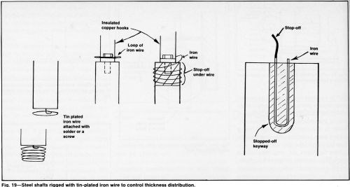
Cold-drawn wire is often too stiff for many applications. Any blue, brown or black oxide that forms when the hard wire is annealed should be removed by a dip in hydrochloric acid. Scale on hot-drawn wire should be removed by pickling. Zinc should be removed from galvanized wire to avoid contamination of the reverse-current etch solution.
After oxide or zinc removal, a flash of tin in a bath with no brighteners is advisable to prevent rusting. The tin also facilitates soldering and provides a good contact surface for electrical connections. The success of any thief depends on a good connection.
Incompletely removed scale produces a large volume of hydrogen during plating because of the low overvoltage of the oxide. Small spots of residual scale sometimes are difficult to see unless the wire is carefully inspected. Scaled spots close to the work piece surface will cause severe gassing that disrupts thickness distribution on functional areas.
The material used to construct a thief or guard must be compatible with the material to be plated and withstand the pretreating and plating cycles without dissolution or becoming passivated or causing an immersion deposit on the work. Iron and steel are suitable with most basis metals except those such as aluminum or magnesium that require a nitric acid dip. The evolution of poisonous nitric oxide gas and excessive iron or steel corrosion rule out iron and steel. High purity aluminum thieves can be used with aluminum or magnesium work pieces. With non-ferrous metal substrates, guards of a similar metal should be used whenever possible.
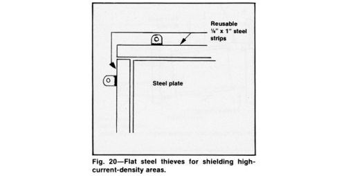
Figure 20 shows how flat strip thieves can be used effectively to guard areas that tend to burn, roughen excessively or sometimes blister. Outside corners are very susceptible to such defects.
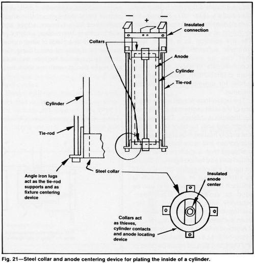
When the inside of a cylinder is plated, a steel collar can be used to incorporate a nonconductive device for centering the anode and act as a thief to control thickness build-up, as indicated in Fig. 21. The cost of such a fixture is justified by the excellent distribution obtained with it. Thin, cold-rolled steel can be inserted if it is first folded in towards the open ends, as illustrated in Fig. 22 and then pressing it back into a circular shape. This kind of thief can be either discarded or stripped in inhibited hydro-chloric acid before reuse.
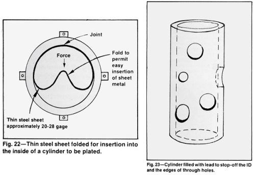
The use of molten lead or lead alloy to fill blind or through holes and hollow parts, such as valves, hydraulic and pneumatic components is an excellent way to stop-off internal surfaces while providing an effective guard for the edges of holes, cut-outs or other irregular openings in the surface to be plated (Fig. 23). A sheet or form should be plated with a thin layer of smooth chromium to provide a smooth surface on the lead and promote easy release from the form. With a truly tight fit, there is no need to smooth and trim the solidified lead. The open end of a hollow cylinder can be adequately sealed by clamping a flat steel plate firmly against the end while the lead is being poured. A thick (1 in.) plate will hasten the lead solidification.
Metallurgical approval of lead or lead alloy should be obtained before use. Tin-lead solder and other low melting alloys may be suitable when the higher melting point of lead is critical. The surface tension of some of these alloys may be too high to permit all openings to be filled perfectly and some may not be compatible with the preplate cycle required for the substrate. The lower melting alloys are more difficult to chill below their melting point than lead and might require tighter fitting molds 
Workers must be trained to handle hot metal carefully. Although use of hot metal involves the limitations noted above, the procedure is one of the best for producing square, defect-free edges on openings in small steel cylinders and avoids the expensive and difficult alternative procedures of plating the edges of the holes and removing the deposit by grinding.
Reference
1. E.C. Knill, Plating & Surface Finishing, 75 (1), 62-69 (1989).
About the Author

Edmund C. Knill is retired from M&T Chemicals as a research associate. He joined the company in 1970 after serving in various capacities, including technical director, for the Chromium Corp. of America over a span of 30 years. Mr. Knill holds a B.Ch.E. degree from Clarkson College and was a member of the AESF Newark Branch.
RELATED CONTENT
-
Electroplated Tin-Nickel Coatings as a Replacement for Nickel to Eliminate Nickel Dermatitis
This paper is a peer-reviewed and edited version of a paper delivered at NASF SUR/FIN 2013 in Rosemont, Ill., on June 12, 2013.
-
A Pulse/Pulse Reverse Electrolytic Approach to Electropolishing and Through-Mask Electroetching
Research at the authors’ laboratories has focused on pulse/pulse reverse electrolysis on cathodic processes, such as hard chromium plating from non-hexavalent chemistries. This papers describes studies into pulse/pulse reverse electrolysis as applied to electrochemical metal removal processes, such as electropolishing and electroetching.
-
Defects in Hard Chromium Deposits Part I: Causes and Cures
The causes of and remedies for defects in hard chromium deposits are explored in the first of this two-part P&SF article from 1984. Photomicrographs and SEM (scanning electron microscope) photographs will illustrate that most defects in various hard chromium deposits arise from defects in the basis metal. These defects may be in the original metal surface or may be caused by preplate finishing. Homogeneous hard chromium deposits can be produced only by eliminating these defects. Practical suggestions and procedures will be given.


