

A handheld profilometer like the one shown here was used to measure surface roughness on a Hull cell panel. Five measurements were taken and averaged at current densities of 20, 40 and 80 amps/ft2. A positioning jig allowed the panel to be measured at exactly the same place for each measurement.

There are three fundamental characteristics that define surface texture. The lay is defined by the straight black line, waviness is the red dashed line, and roughness is the high-frequency blue line.

Fig. 1. In this illustration, the Hull cell panel on the left was scribed to a depth of 0.30 micron. Center, the bottom of the scribed panel was plated with nickel. Right top, the panel was bisected and polished. Right bottom is a representation of the anticipated result.

Fig. 2a. This plotted data represents the surface profile of a panel that was scratched mechanically before nickel plating.

Fig. 2b. This plot shows the data acquired after the nickel plate described in the text.

Fig. 3a. Scanning electron micrographs of scribed panels taken before and after nickel electroplating demonstrates the ability of a nickel deposit to level rough surfaces. Here is the micrograph taken before plating.

Fig. 3b. Scanning electron micrographs of scribed panels taken before and after nickel electroplating demonstrates the ability of a nickel deposit to level rough surfaces. Here is the micrograph taken after plating.

Fig. 4a. This chart illustrates the improvement in Ra value from the prescratched Hull cell panel before nickel plating and after plating.

Fig. 4b. This chart illustrates the improvement in surface roughness as a function of brightener load.
Share
Decorative nickel plating can yield one of the most beautiful surfaces possible by electroplating. Besides a lustrous or satin appearance, it produces a finish that is corrosion-resistant and versatile, and may be used as a base metal for a final decorative chromium deposit.
Unfortunately, many electrodeposited metallic coatings deposit more on surface peaks than on valleys, because the electric field strength (current density) is greatest in these areas1. While control of the properties of nickel deposits has been well-chronicled2, one important feature termed “leveling” makes nickel plating attractive and is different in its ability to cover imperfections over the plated surface.
Featured Content


Leveling is desirable in nickel plating because it reduces the amount of surface preparation that must happen before plating, and in cases where the top deposit will be chromium, it may eliminate an additional buffing step to the nickel. Here, we investigate the role of surface roughness and its measurement in determining the health of a nickel bath.
Defining Roughness
Three irregularities are considered to make up the general term “surface texture.” The first, which has the longest wavelength, is defined as the lay. The lay is the dominant pattern of texture on the surface. The second irregularity is waviness, which includes a more widely spaced (shorter wavelength) deviation from the ideal shape, usually considered to be a flat plane. Finally, the third component is roughness, which represents the finest irregularity (shortest wavelength) of a surface. We are confining this discussion strictly to roughness.
There are many parameters described in literature that address specific components of roughness and its calculation. The most common, one-dimensional form of roughness measurement in the United States is roughness average (Ra), which is defined in ASME B46.1 as “the arithmetic average of the absolute values of the profile height deviations from the mean line, recorded within the evaluation length.” According to some sources, there are more than 100 methods for expressions of roughness.
Techniques for Measuring Roughness
Profilometry is the science of measuring roughness and is divided into two categories: optical profilometry and contact profilometry. Optical instruments are interferometric tools and provide three-dimensional images of a surface as well as its roughness data. One important advantage of an interferometric tool is that it uses the reflection of white light from the surface to form the image. This offers a non-destructive method for examining the surface. This feature is important when examining soft materials such as brass, for example, through which a stylus might scribe a groove.
Contact profilometry is a common technique for plated or surface-polished samples. A plating shop may, for example, wish to determine the improvement of surface texture from rough to smooth after a treatment or plating process. Contact profilometers use a stylus to examine the surface, much in the way a phonograph’s needle travels over a record. As the stylus travels over surface features, the deflection of the stylus up and down is measured and recorded.
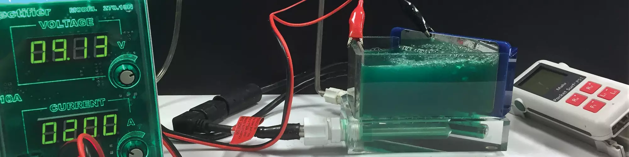
In a shop, the health of a decorative nickel bath may be evaluated by periodic chemical analysis of the bath components, but if there is a “canary in the coal mine” for nickel baths, it is the amount of leveling that is achieved on the surface of the plated part. When technical experts in the field are called upon to troubleshoot nickel baths, it is highly valuable to first investigate the degree to which the bath can level a Hull cell panel. The analytical process includes steel Hull cell panels that have been mechanically scratched at a machine shop to achieve an Ra of approximately 0.30 micron; a jig that precisely positions the panel before and after measurements; and a handheld, battery-operated profilometer. First, the unplated Hull cells panels are tested for surface roughness, and the measurements are recorded for 20, 40 and 80 amps/ft2. The panels are then nickel-plated and measured again. Reductions in surface roughness are recorded and reported as a percentage of improvement.
Profilometry in Product Development
To demonstrate the effect of the nickel layer on leveling the surface, we prepared a standard Hull cell panel in the following manner:
The bottom third of the panel was scratched with a grinding wheel to a depth of approximately 0.30 micron. The panel was placed in the mounting jig, and a roughness measurement was taken. The panel was then plated in a bright nickel bath at 5 amps for 150 seconds to obtain a nickel thickness of 6.34 microns, measured by x-ray fluorescence. This closely matched the anticipated theoretical thickness (based on Faraday’s law and considering 100 percent cathodic efficiency) of 6.402 microns. The specimen was then returned to the mounting jig to the point of the original roughness measurement, and a second roughness measurement was taken.
The difference in surface profiles is shown in Figures 2a and 2b. Note that, while some degree of waviness remained in the nickel-plated plot, the roughness, indicated by the travel of the stylus before plating, was mostly gone. Note also that a very small degree of lay was exposed in the plated measurement.
Scanning electron micrography offers visual confirmation of the results determined by the profilometer. Figures 3a and 3b illustrate the impact of the nickel plating described above. The micrograph on the left represents the panel after it had been scribed for roughness. The Ra value was determined by profilometry to be 0.377 micron. The sample on the right is the nickel-plated example measured to a surface roughness of 0.12 micron.
During the development of an optimum leveling package, we ask two questions: What is the correct additive or mixture of additives, and what is the proper concentration? Use of profilometry helps quantify this process.
In duplex nickel systems, brighteners are added to the semi-bright layer to give a uniform deposit. For the bright nickel layer, sulfur-containing carriers are added to give a fine and uniform grain structure. Sometimes a secondary brightener and leveler is added. An excellent (but not complete) list of brighteners can be found in the Jack W. Dini book ”Electrodeposition Materials Science of Coatings and Substrates.”3 An investigation into one family of reagents, the acetylenics, revealed that while some components are very effective at the upper ranges of current density, they offer little improvement at lower current densities and in some cases can even cause additional roughness (see Figures 4a and 4b).
Some additive blends perform well only at higher current densities, while some offer enhanced leveling at lower current densities at the expense of high-current-density performance. With this data, the engineer can determine if the proper remedy to the problem is a single component or a combination of materials that takes advantage of the high- and low-current-density leveling abilities of multiple additives.
The leveling that is typically corrected by these additives improves roughness, but it is not efficient in correcting waviness and is of no help toward the improvement of lay. With the best leveling package selected, one can turn attention to the best concentration of the leveling package in the bath.
To determine the proper concentration of brightener, the best-performing material from a single current density was measured at different concentration loads. The results of that work are found in Figures 4a and 4b. As expected, the best performance (greatest degree of leveling) occurred again at the highest current density. Note, however, that this work shows that beyond a certain load (approximately 0.2 g/L) there is very little benefit from increased doses of brightener. On the other hand, things go badly very quick if the load falls below 0.1g/L. Insufficient brightener can lead to dull parts or a finished product that requires buffing. Excessive brightener may mean little improvement in performance and create increased costs.
Similar results were reported by Oniciu and Muresan4 studying the role of thiourea as an additive for nickel solutions. They related leveling and brightening to the dimensions of the formed grains. Deposits with finer grain structure resulted from high current density, and additives adsorbed preferentially at micropeaks result in local resistance increasing current density in the depressed areas or grooves, thereby contributing to leveling5.
Bath Repair
Nothing beats a full chemical analysis to fully understand the balanced components in a bath, but a five-minute test with a Hull cell panel and a profilometer can indicate whether the quality of the plated parts is deteriorating. The addition of a secondary brightener before parts fall below acceptable quality-control limits helps reduce lost time and expense.
Watts-type nickel baths in combination with organic additive packages have the ability to level the high frequency imperfections below a nickel-plated surface, reducing roughness and improving brightness. Roughness may be quickly, economically and easily quantified by a handheld profilometer, useful in the laboratory or in the field. Compilation of the profilometry data allows the researcher to develop and prepare additive packages that are designed to improve surface roughness in high- or low-current-density regions, or address a broader current-density region through the blending of specific materials. Nickel baths that suffer from low brightener load, organic contamination, additive imbalance or organic consumption may be corrected by following deterioration of leveling performance.
References:
1Jack W. Dini, Electrodeposition Materials Science of Coatings and Substrates, Noyles Publication, p. 203, (1993).
2G. A. Dibari, Nickel Plating, Metal Finishing Guidebook, 2012-2013, pp. 334-349.
3Jack W. Dini, Electrodeposition Materials Science of Coatings and Substrates, Noyles Publication, p. 211, (1993).
4L. Oniciu, L. Meuesan, Journal of Applied Electrochemistry, 21, (1991), 565-574.
5S.A. Watson, J. Edwards, Transactions of the Institute of Metal Finishing, 34, 167, 1957.
About the Authors
Mark Schario is the executive vice president of Columbia Chemical. Dr. Lawrence Seger and Christian Kissig also contributed to the article. For information, please visit columbiachemical.com.
RELATED CONTENT
-
Aluminum Anodizing
Types of anodizing, processes, equipment selection and tank construction.
-
Blackening of Ferrous Metals
The reasons for installing an in-house cold blackening system are many and varied.
-
Stripping of Plated Finishes
The processes, chemicals and equipment, plus control and troubleshooting.


