Measuring E-coat Throwpower
Electrocoat’s strength lies in its throwpower, but how can applicators take the most advantage of this characteristic?
#masking #pollutioncontrol
Throwpower has become a very popular and powerful word in the cathodic epoxy electrocoat industry.
Featured Content
So-called high-throw electrocoat is designed to improve the effectiveness and productivity of e-coat application; material consumption decreases, higher line speeds and greater rack density are some of the claims attributed to the technology.
Are these claims true? What is throwpower, and why has it vaulted to the top of electrocoat attributes?
The conventional definition of throwpower is electrocoat’s ability to be deposited in recessed areas. In fact, this is electrocoat’s main advantage over other coatings since it provides corrosion protection in difficult-to-coat areas.
Conventional electrocoat throwpower is measured using a two-panel throw box, which determines the distance electrocoat “throws.” The box panels are set a distance apart, sealed on the sides and open on the bottom. The box is then coated in an electrocoat bath in the laboratory under defined conditions. The result is that the exterior of the box is fully coated and the interior is only partially coated. The distance of the interior coating is measured, and this is the e-coat’s throw.
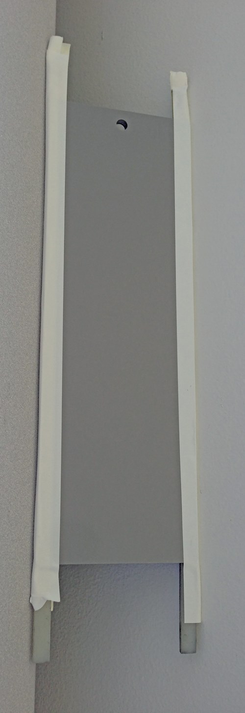
Typical two-panel throw box.
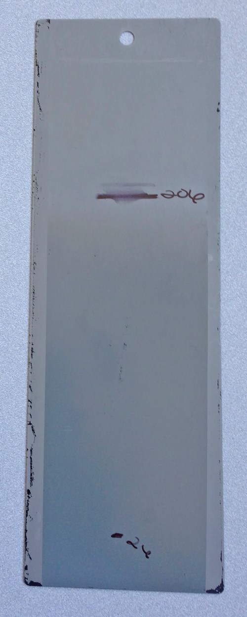
Two-panel throw box results.
Interior Side Measurements
The throwpower of a conventional electrocoat creates a film thickness gradient. Achieving a minimum film thickness on the interior requires more film thickness on the exterior for a conventional electrocoat. This effect creates a film thickness gradient across a rack of parts and increases electrocoat usage; the greater the rack density, the greater the film thickness gradient.
The introduction of thin-film pretreatments in automotive assembly plants has changed how we look at throwpower. Thin-film pretreatments have a higher surface conductivity than phosphate pretreatments, therefore they reduce the voltage needed to achieve electrocoat film thickness on them. A lower coating voltage should increase the film thickness gradient of a conventional electrocoat. More film thickness should be applied to the exterior in order to achieve the minimum interior film thickness.
This lower coating voltage influenced electrocoat suppliers to rethink—or redefine—how to achieve minimum film thickness in recessed areas. The two-panel throw box does not predict film thickness gradients, so they developed a four-panel throw box to understand the effect of thin film pretreatments on throwpower and film thickness gradients.
The four-panel throw box method uses four evenly spaced panels with holes drilled in three of them. The panels are enclosed on all sides and the bottom, and the holes allow the paint to enter the box and provide the only means for the electricity to reach the interior cavities of the box. The box is coated with an e-coat bath in the laboratory under defined conditions, and the film thickness on the front and back of each panel is measured after curing.
Throwpower and film thickness gradient is determined by comparing the film thickness on an interior panel (the G face) with the exterior panel (the A face). The comparison is expressed as a percentage, and the higher the percentage the greater the throw and less film thickness gradient.
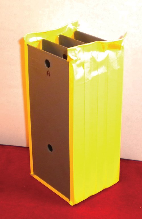
Typical four panel throw box.
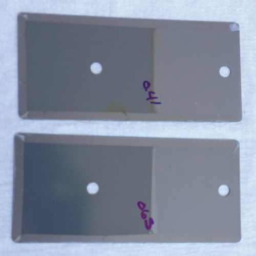
Four panel throw box results.
Electrocoat suppliers developed a new generation of coatings to use with thin-film pretreatments. These provide self-limiting film thickness, which only allows the film to coat so thick. The outside portions of the ware package stops building film, enabling complex geometries and centerline parts to build film rapidly.
Self-limiting E-coat
Self-limiting electrocoat enables systems with dense part concentrations to achieve film thickness on the inside of the rack that is very similar to the parts near the anodes. These next-generation electrocoats can achieve minimum interior film thickness while reducing exterior film thickness, which saves on electrocoat usage.
Some plants have experienced a reduction in electrocoat usage as high as 25 percent. The new electrocoats have been such a success that some automotive manufacturers have reduced the exterior film thickness requirements where the new electrocoats are being used. They have also proven to work with phosphate pretreatments.
The formula advancements made to gray electrocoat are being applied to black cathodic epoxy electrocoat as well. Some are performing trials of a new black electrocoat designed for decreasing film thickness.
Can these new electrocoats help you? First, determine the amount of coating material that is wasted due to film thickness gradients. To accurately quantify film gradients, the film thickness of parts should be monitored during periods of normal production. Perform these calculations on different days with different types of parts and rack densities. The film measurements need to be done on at least 10 groups of racks at a time.
Indexing System
Measure the film thickness on each rack in the group and calculate the weighted average for the rack; the rack in the center should have the lowest film thickness.
For example, id are five racks, the weighted average should be 20 percent for each rack. Take the film thickness of each rack and multiply by 0.2, then add all the films. This will be the average for the group of racks.
Do this same measurement and calculation for all 10 groups of racks. Add all the group averages and divide by 10. This will be the film thickness average for the ten groups of racks. Compare this average to the minimum film thickness requirement.
If the average for the group is 0.8 mils and the minimum is 0.6 mils, then this would indicate a material overage of approximately 33 percent. If your material overage is greater than five percent, consider changing electrocoats to one of the new self-limiting electrocoats.
Joseph Subda is with Axalta Coating Systems. He can be reached at joseph.j.subda@axaltacs.com.
RELATED CONTENT
-
Salt Spray Vs. Cyclic Corrosion Tests
Joseph Subda, ecoat specialist for Axalta Coating Systems, explains the difference between these two corrosion resistance tests.
-
Coating Systems with the Best Long-Term Performance
The best protection against corrosion and UV exposure, says Axalta’s Mike Withers, is electrocoat and a super durable powder coating.
-
What is Electrocoating?
E-coat can produce uniform finishes with excellent coverage and outstanding corrosion resistance.


