Mechanism of the Plating Process - The 8th William Blum Lecture
This paper is a re-publication of the 8th William Blum Lecture, presented at the 54th AES Annual Convention in Dallas, Texas, on June 19, 1967. Dr. Henry B. Linford discussed the transition of electroplating from an art to a science as the mechanism of the plating process became better understood.
#basics
by
Dr. Henry B. Linford
Featured Content
Recipient of the 1966 William Blum
AES Scientific Achievement Award
Originally published as H.B. Linford, Plating, 55 (1), 35-39 (1968).
Editor’s Note: This paper is a re-publication of the 8th William Blum Lecture, presented at the 54th AES Annual Convention in Dallas, Texas, on June 19, 1967. A printable PDF version is available by clicking HERE.
Since 1947, the literature has contained a considerable volume of material dealing with the mechanism of metal deposition. These studies have been made using very pure metal electrodes and highly purified solutions with oxygen exclusion being the general rule. These are necessary precautions in order that the reaction can be studied on a purely theoretical basis. Platers, however, do not take these precautions; thus, conclusions drawn from such theoretical, mechanistic studies cannot be safely applied to a practical plating process. The plater needs to know more about the deposition process in the presence of the soils and contaminants which he is forced to accept. Some of these conditions have been studied and we are gradually gaining a better understanding of the mechanism of the plating process.
It is well known that, in order to control a process properly and make improvements in a scientific manner, the mechanism of the reactions involved must be understood. The plating process developed as an art in the 1800s when very little of the chemistry of the processes was understood. The artisan or tank man knew from experience that certain ills could be cured by making changes in solution composition or mode of operation. These adjustments were usually moderately successful; however, common to all such procedures, serious difficulties could not always be avoided. The development of a fundamental understanding of the chemistry of aqueous solutions through the work of Faraday, Gibbs, Helmholtz, Arrhenius and others in the 1800s and early 1900s gave us a better understanding of plating.
Professor W.D. Bancroft of Cornell in 1913l published what he called the axioms of plating. They are as follows:
- Bad deposits are due to excessive admixture of some compound or to excessively large crystals.
- Excessive admixture of any compound can be eliminated by changing the conditions so that the compound cannot precipitate.
- Increasing the current density, increasing the potential difference at the cathode, or lowering the temperature, decreases the size of the crystals.
- The crystal size is decreased when there are present, at the cathode surface, substances which are adsorbed by the deposited metal.
- If a given solution will give a good deposit at any current density, it will give a good deposit at any higher current density, provided the conditions at the cathode surface are kept constant.
- Treeing is facilitated by a high potential drop through the solution and by conditions favorable to the formation of large crystals.
Professor Bancroft had these axioms printed on cards and handed them out during the discussion following a symposium on electroplating, held by the American Electrochemical Society in Atlantic City in 1913. The discussion that followed showed what a "can of worms" he had opened, pointing out the difference in thinking between the electrochemists and the practical platers. Such old-time platers as Charles H. Proctor and George Hogaboom were present. Mr. Hogaboom2 foretold the AES Research Program during this same discussion period when he said, "This day marks an epoch in the history of electroplating in this country, and the gentlemen who have compiled this collection of formulas should have the thanks of the American Electroplaters' Society for the very great service they have performed to the practical electroplater.
"One of the greatest needs of the electroplating industry today is co-operation between the practical man and the electrochemist. One of the ways I think this can be accomplished is by having the universities that have courses in electrochemistry cooperate directly with the plater."
As a result of improved methods of analysis, the introduction of the pH meter allowing accurate pH control, and an increased interest in the plating process by people with backgrounds in physical chemistry, rather successful electroplating was being accomplished by the 1930s. However, it was still too strongly dependent upon the platers' "know-how" to be classified strictly as a science. In the latter 1940s, research on the kinetics of the reactions was initiated. Through these studies, it should be possible eventually to gain an understanding of the process sufficient to put it on a sound scientific basis.
The background of kinetic studies is deeply rooted in overvoltage researches. In 1905, Tafel3 gave us empirical relationships between overvoltage and current density. The constants of the Tafel equation were not given any theoretical interpretation until the development of the theory of the rate process, so ably summarized in the book, "The Theory of Rate Processes," by Gladstone, Laidler and Eyring in 1941.4 Up to this time, about the only overvoltage measurements that were meaningful were those made on the hydrogen deposition reaction, and the most valuable of these studies were conducted on mercury surfaces. There are many reasons for this limitation; among them is the fact that on mercury surfaces the condition of the electrode is extremely reproducible. Also, the overvoltage was fairly large, making corrections for ohmic overvoltage and concentration overvoltage relatively unimportant.
The overvoltage, often called overpotential of a reaction, is defined as the excess voltage over the reversible potential that must be applied to a reaction to cause it to proceed at a particular rate. The researches of Tafel show that, at least at higher current densities, the overvoltage varies as the logarithm of the current density. The overvoltage is commonly broken into three component parts; ohmic, concentration and activation. It is the activation overvoltage which is of theoretical interest in rate studies. As in the case of metal deposition where ohmic overvoltage and concentration overvoltage may be of significant size, some method must be used to measure the activation portion of the overvoltage. The ohmic overvoltage is a direct result of the IR loss through the electrolytes since the reference electrode must be placed a finite distance from the working electrode; some fraction of this IR loss is normally included in overvoltage measurements and, thus, proper correction must be made. Concentration overvoltage results from the removal of reactants or the addition of products to the cathode film as a result of the electrode reaction. Using the methods of Rosebrugh and Miller,5 concentration polarizations may be calculated. When galvanostatic techniques are used,6 the three overvoltages are separated on a time scale (Fig. 1) thus making it possible to read directly the activation overvoltage. The distance on the y axis from the zero point to the beginning of the trace gives the ohmic overvoltage. The vertical distance from the beginning of the trace to the plateau is the activation overvoltage. At approximately 5 × 10⁻⁴ sec insufficient time has elapsed to develop any measurable concentration overvoltage.
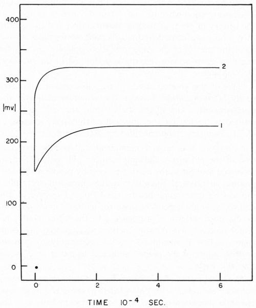
Figure 1 - Typical charging curves i = 89 ma/cm2. Curve 1, atomizer clean cathode; Curve 2, cathode covered with 2.2 × 10⁻⁷ g/cm2 stearic acid, freshly applied.
Early studies on metal deposition overvoltage were not successful because of the difficulties of eliminating the above mentioned irreversible effects plus the near impossibility of getting a solid metal surface into a reproducible condition. In addition, since the metal deposition overvoltages were small, it was soon realized that stringent control of all ambient conditions was necessary.
Again reaching back to hydrogen overvoltage studies, theoretical treatment of data can be used to delineate possible reaction mechanisms. Starting with this, it is possible to make the same type of predictions in the case of metal deposition. We know from an analysis of the problem that ions in the bulk of the solution must be transferred to the electrode surface. This transfer can be accomplished by means of convection, both natural and forced, and by transport.
When an ion approaches an electrode surface, it encounters a discontinuity a few molecular diameters distant from the real surface. When a metal is placed in an electrolyte of its ions, some metal will either deposit or dissolve. In the case of a situation where the metal tends to go into solution, an excess negative charge is left on the metal surface which must be neutralized by an excess of positive ions next to or near the surface. This is commonly called the electric double layer. The field strength in this region is very great, approximating 108 V/cm, if one has a voltage drop of one volt at the electrode.
As the ion proceeds through the double layer, the hydration sheath is first altered and then stripped. The ion is then discharged one charge at a time. The ion, partially discharged ion or completely discharged atom, then migrates by surface diffusion to the site on the electrode surface of lowest free energy where it is incorporated into the crystal structure of the surface. When a chain of reactions of this nature is encountered, oftentimes one step is much more irreversible than its predecessor or the steps following, and is termed rate-limiting. One could liken it to water flowing through a pipe with many valves. If one valve is nearly closed and all the rest are open, the resistance to flow depends almost completely on the nearly-closed valve. It is easy to see that we often have conditions where more than one step may be influential, in which case, a mixed control would result. In the great majority of cases, however, it appears that one step is rate-controlling and this step can often be predicted from overvoltage measurements.
The physical form of an electrodeposit, which will determine its economic value, is influenced by the manner in which a deposit is formed. It is well known that, when a deposit is applied, the crystal structures tend to follow that of the substrate; thus, we see that, if anything is done to give us a poor structure on the first layer, a faulty deposit may well result.
A great deal of credit must be given to Professor J. O'M. Bockris and his co-workers7-9 for their pioneering researches in electrode kinetics. For the bulk of their studies they have used electrodes in the form of spheres at the end of wires formed by fusion. The solutions used have been ultra-pure, and thus was developed the beginning of an understanding of plating reactions under idealized conditions. It is very difficult for the practical man to make any direct application of this work. It is not the intent of such research to be directly applicable to practice, but it is absolutely vital to amass large amounts of such research in order to gain an understanding of the much more complicated deposition process.
The reason for the lack of theoretical knowledge of the practical plating process can best be illustrated by the fact that theoretical researchers in the field of overvoltage studies continually strive for purer solutions and scrupulously clean metal surfaces. Professor Delahay10 in the introduction to his recent book, Double Layer and Electrode Kinetics, brings out the need for utmost cleanliness. For the theoretical chemists, the existence of impurities must be avoided. To the practical plater, solutions that are available will always be contaminated. The plater never introduces an absolutely clean metal surface into ultra-pure electrolytes; thus, to understand the mechanism of the plating process, we must learn the effect of the various contaminating materials. These contaminating materials may at times be substances added deliberately to achieve certain results. For example, brighteners used in nickel plating would be considered contaminants in this sense.
Our researches at Columbia University, carried on with the assistance of the AES Research Project No. 12, were directed toward a beginning of the understanding of this problem. Project 12 had as its objective the cleaning and preparation of metals for electroplating. The first project fellow, Dr. E.B. Saubestre, among other things developed the atomizer test.11 Everyone agrees that this was a real advance over water break; however, it did not achieve uniform acceptance in the plating shop. In order to determine whether or not the added sensitivity would be vital to the plater, Grunwald12 studied the effect on adhesion of various quantities of stearic acid applied to the metal surface. In this study, nickel from a high pH Watts nickel bath was deposited on a copper surface (Fig. 2). A scribed area was soiled using the evaporation technique described by Saubestre.13 On this cathode, part-clean, part-soiled, it can be seen very clearly that hydrogen bubbles adhere to the soiled areas, while the clean areas were free. Studies of the current efficiency for normal thickness of plate did not indicate that any appreciably greater fraction of the current went to hydrogen deposition in the case of a soiled area as compared to that of the clean. The hydrogen bubbles formed immediately upon application of the current and did not continue to grow, and very few were evolved. This exploratory research led us into a very extended study on the electrode kinetics of metal deposition of clean and soiled surfaces. Dr. Bockris' studies14 were made with cathodes in the form of small spheres on the end of wires. Such surfaces were impossible to soil reproducibly. Dr. Karasyk6 developed a method to determine the overvoltage of copper deposition from copper sulfate solution using flat-plate electrodes which could be reproducibly soiled by the technique previously worked out in Project 12. Dr. Karasyk was able to check the values obtained by Professor Bockris when clean, freshly reduced electrodes were used. The results of Dr. Karasyk's work are shown in Fig. 3. It has been shown previously that the slow step in the deposition of copper was the discharge process.14
Slow Fast
Cu++ + e- ⇒ Cu+ and Cu ⇒ Cu+ + e-
Fast Slow
Cu+ + e- ⇒ Cu Cu+ ⇒ Cu++ + e-
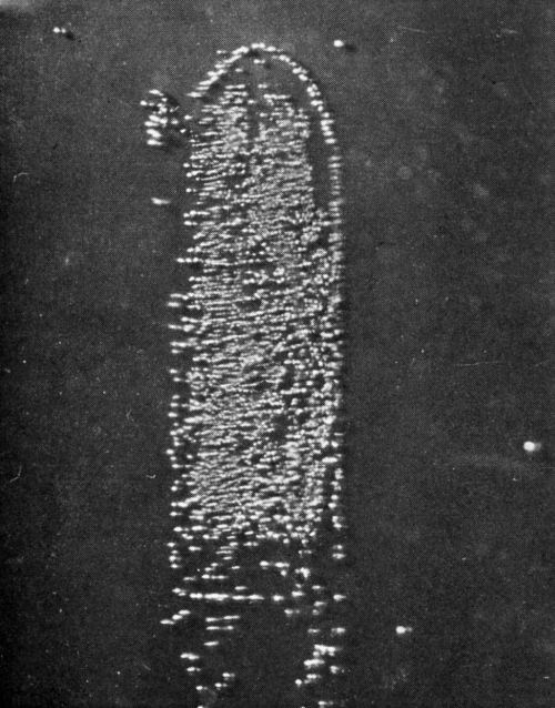
Figure 2 - Soiled area coated with 0.8 monolayers of stearic acid. 2× area magnification.
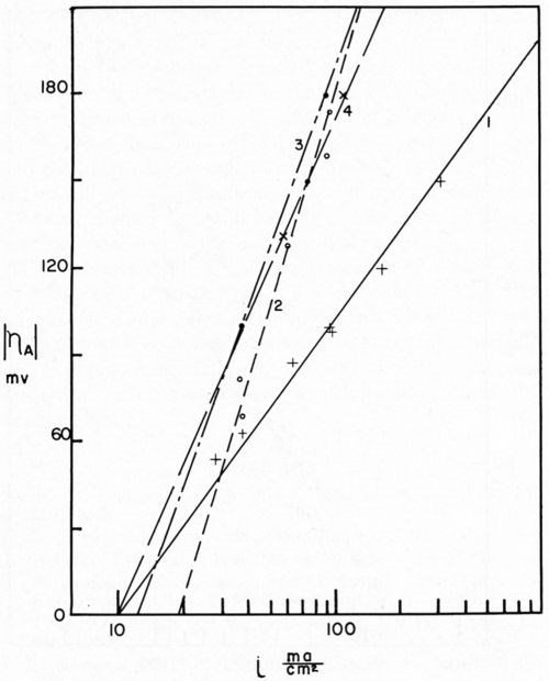
Figure 3 - Tafel lines for various cathode treatments. Curve 1, atomizer clean cathode; Curve 2, cathodes with 2.2 × 10⁻⁷ g/cm2 stearic acid, freshly applied; Curve 3, cathodes with 2.2 × 10⁻⁷ g/cm2 stearic acid, applied 24 hr before plating; Curve 4, cathodes freshly soiled with 2.3 × 10⁻⁷ g/cm2 paraffin oil.
Bockris stated that, since Io is the same for the anodic and cathodic process, the same rate-determining process is effective for deposition and dissolution. Dr. Karasyk's study showed that with a decrease in alpha, transfer coefficient, the slow step of surface diffusion is compatible with this shift in the kinetic parameters. Thus, he postulated that soil on the surface of the electrode impeded the surface diffusion process. In addition, Dr. Karasyk showed that a freshly deposited (unoriented) stearic acid film increased the exchange current. This is a surprising result since, in the bulk of the current density range of interest, soiling in this fashion results in a higher overvoltage, greater irreversibility, which is generally associated with a lower exchange current. Some work of Turner,15 to be discussed later, exhibits the same unusual phenomena. Another interesting by-product of Dr. Karasyk's work was the overwhelming evidence, that under the conditions of his experiments, the copper plates on top of the stearic acid to yield surfaces with the kinetic parameters of clean copper (Fig. 4). Another point of interest here was that, in the presence of a soiled surface, the capacitance of the double layer was markedly reduced; 50-60 microfarads/cm2 for clean electrodes compared with about 7-26 microfarads/cm2 for soiled. Dr. Mary Anne Farrell16 then studied the effect of soiling on hydrogen overvoltage for the reaction hydrogen deposition on copper. Her results can be summarized in Fig. 5, in which she demonstrated that soiling decreases the transfer coefficient alpha and increases the exchange current. This leads to the unusual situation, whereby, at low current densities, the overvoltage is reduced in the presence of soil, whereas, at high current density, it is increased. We see, then, an explanation for the results obtained by Grunwald, namely that, when nickel is deposited on the copper in the soiled areas, we get more hydrogen production than on the clean areas at the beginning of the deposition. Nickel deposition always proceeds at something less than 100 per cent current efficiency so, even though Grunwald used 1 A/dm2, the current density of hydrogen deposition would be in the range predicted by Farrell's results where the overvoltage is reduced, thus favoring hydrogen deposition on the soiled areas. Of course, the bubbles grow and cover the active centers for hydrogen deposition. Continued hydrogen deposition could not occur since surface forces were such that these bubbles would not be dislodged.
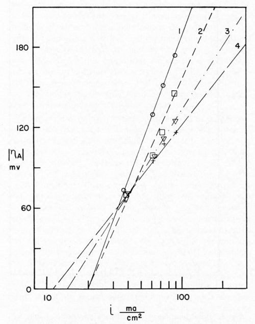
Figure 4 - Sequence of Tafel lines for cathodes freshly soiled with 2.2 × 10⁻⁷ g/cm2 stearic acid. Curve 1, 0 coulomb/cm2; Curve 2, 0.5 coulomb/cm2; Curve 3, 1.5 coulomb/cm2; Curve 4, 3.5 coulomb/cm2.
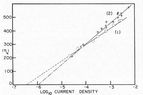
Figure 5 - Tafel lines for copper cathodes. (1) Atomizer clean electrodes. (2) Soiled with one monolayer stearic acid (2.2 × 10⁻⁷ g/cm2). (ηA), absolute values of overpotential in mv; log io current density, current density in A/cm2.
Nickel deposition on clean and soiled nickel surfaces was studied by Dr. Danna.17 It should be remembered that when using the galvanostatic method for overvoltage measurements only the first few milliseconds of deposition are considered. Thus, the next phase of this work required that we obtain current efficiencies as a function of pulse time with sufficient time to allow relaxation of the double layer between pulses in order that the charging curves could be interpreted. The results of this study showed that, in the case of clean nickel surfaces, deposition efficiencies were reduced if pulses of one second or shorter were used. Even at the shortest pulse time used, 2 milliseconds at 100 ma/cm2, some nickel was deposited and the efficiency was dependent on the total coulombs per cm2 (Figs. 6 and 7). With soiled surfaces (approximately 5 monolayers of stearic acid), nickel does not start to deposit until after 0.065 coulomb/cm2 have passed. This is independent of pulse time and current density. In the case of the soiled surfaces, apparently more hydrogen must be deposited in order that the conditions in the cathode film are correct for metal deposition than in the case of the clean nickel. Much more work is necessary in this area to completely understand ramifications that this exploratory research has uncovered.
As mentioned, Dr. Dennis Turner15 has used similar techniques to study the effect of addition agents on the deposition of copper from copper sulfate. Also, effects of inhibitors can be studied using electrode kinetic data. An example is that of Kaesche and Hackerman.18 These two are examples of the effect on the kinetics of chemical reactions induced by adding "foreign" substances to the solution. The electroplater is faced with two problems: first, all of the solutions he uses will be contaminated through the use of technical grade reagents or deliberately by the addition of brighteners, etc.; second, the cathode will never be absolutely clean, i.e., free from adsorbed organic materials or oxides. It is my belief that we will understand addition agents in general and brightening and leveling agents in particular only when we have a clear understanding of the mechanism of the plating process.
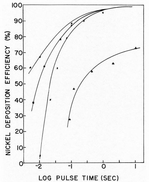
Figure 6 - Nickel deposition efficiency vs. pulse time. ∆ = 5 mA/cm2, × = 10 mA/cm2; □ = 50 mA/cm2; ○ = 100 mA/cm2.
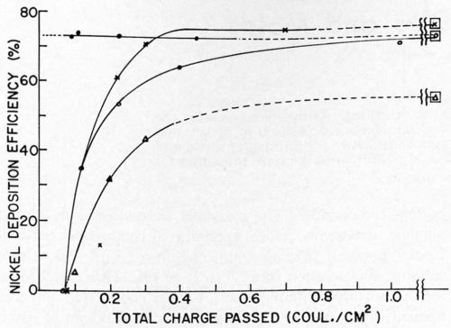
Figure 7 - Nickel deposition efficiency vs. total charge passed. ● = clean cathodes, 45 msec/pulse, 100 mA/cm2; ○ = soiled cathodes, 45 msec/pulse, 100 mA/cm2; × = soiled cathodes, 100 msec/pulse, 100 mA/cm2; ∆ = soiled cathodes, 10 msec/pulse, 100 ma/cm2; □ = around any of the above symbols indicates efficiency obtained under the same conditions on clean cathodes with a large total charge passed.
It is too early to predict all of the conclusions that we will eventually be able to draw when a large volume of such data is available. Only a bare beginning in this complicated area has been made; however, the results so far obtained clearly outline a procedure that may be used and it is sincerely hoped that future investigators will continue to amass the necessary data.
References
1. W.D. Bancroft, Trans. Amer. Electrochem. Soc., 23, 266 (1913).
2. G.B. Hogaboom, ibid., 23, 285 (1913).
3. J. Tafel, Z. Physik. Chem., 50, 641 (1905).
4. S. Glasstone, K.J. Laidler and H. Eyring, The Theory of Rate Processes, McGraw-Hill Book Co., N.Y., 1941.
5. T.R. Rosebrugh and W. Lash Miller, J. Phys. Chem., 14, 816 (1910).
6. L. Karasyk and H.B. Linford, J. Electrochem. Soc., 110, 895 (1963).
7. J. O'M. Bockris and N. Pentland, Trans. Faraday Soc., 48, 833 (1952).
8. N. Pentland, J. O'M. Bockris and E. Sheldon, J. Electrochem Soc., 104, 182 (1957).
9. J. O'M. Bockris and E.C. Potter, ibid., 99, 169 (1952).
10. P. Delahay, Double Layer and Electrode Kinetics, John Wiley & Sons, Inc., N.Y., 1965, pp. 1-10.
11. H.B. Linford and E.B. Saubestre, Plating, 38, 713-717, 847-855 (1951).
12. H.B. Linford and J.J. Grunwald, ibid., 46, 1039 (1959).
13. H.B. Linford and E.B. Saubestre, ibid., 40, 489-496, 633-645 (1953).
14. E. Mattsson and J. O'M. Bockris, Trans. Faraday Soc., 55, 1586 (1959).
15. D.R. Turner and G.R. Johnson, J. Electrochem. Soc., 109, 798 (1962).
16. M.A. Farrell and H.B. Linford, Plating, 53, 1110 (1966).
17. P.A. Danna and H.B. Linford, Manuscript submitted to Plating, Doctoral Thesis, Columbia University.
18. H. Kaesche and N. Hackerman, J. Electrochem. Soc., 105, 191 (1958).
About the author

His wife, Rebecca, was also a student at Utah State. His good fortune to meet her during his college years made him a strong advocate of co-educational institutions.
He was awarded a graduate fellowship at Washington State University in 1931 and majored in electrochemistry. Two years later, he received his Master's degree. He was such an outstanding graduate student that he was awarded a second graduate fellowship at Washington State. Turning to inorganic chemistry, he received his Ph.D. from Washington State, and was awarded the 7th Weston Fellowship of the Electrochemical Society at Columbia University and studied there with Professor Colin G. Fink in 1936 and 1937.
He then became associated with the Central Research Laboratories of the American Smelting and Refining Company in Perth Amboy, New Jersey. Four years later, he joined the faculty of Columbia University as an instructor in chemical engineering. In 1946 he was made an assistant professor, and three years later advanced to associate professorship. He became professor of chemical engineering in 1952. For some 15 years, starting in 1947, he was in charge of the Columbia Chemical Engineering Camp in Connecticut.
Dr. Linford was very active in the Electrochemical Society for 25 years and was its national secretary for 10 years. He was president in 1962-63. He was a Fellow in the New York Academy of Sciences. Dr. Linford was Acheson Medalist of the Electrochemical Society in 1960, and in his address stated "... we should make provision to conserve one of our most valuable natural resources, the brilliant mind. Unless we conserve our technical man power, we are threatened with extinction." During his years on the faculty at Columbia, he did more than his share to train young minds toward science and engineering.
Dr. Linford was Director of AES Research Project No. 12, "Cleaning and Preparation of Metals Prior to Electroplating," at Columbia University, beginning in 1949. At the time, more papers had been published on the investigations conducted in this project than any other in AES research.
RELATED CONTENT
-
Polishing vs. Buffing: What's the Difference?
Is polishing the same as buffing? Mechanical finishing expert, Pat Wenino, explains the differences between the two processes.
-
Alkaline Cleaning Guide
Gregg Sanko, Senior Chemist, Oakite Products, Inc. provides an overview of the alkaline cleaning process.
-
The Powder Coating Process
Powder coating is one of the most durable finishes that can be applied to industrial manufactured products, and offers excellent corrosion protection and is very safe because of its lack of volatile organic compounds. To understand the powder coating process you should start with the fundamentals.


