The Move Toward Effective Colorless Zinc-Nickel Passivates
Zinc-nickel passivation continues to be a robust method of extending the corrosion protection of electroplated substrates, as well as providing a visually appealing finish. In the past, clear passivation for zinc-nickel did not offer high levels of corrosion protection. This paper discusses both the mechanism by which passivate films are colored as well as the development of a clear, colorless zinc-nickel passivate that achieves good corrosion protection.
#surfin
Featured Content
A Paper* based on a Presentation given at SUR/FIN 2019 (Rosemont, Illinois)
by
Mark Schario** and Christian Kissig
Columbia Chemical Corporation
Brunswick, Ohio, USA
Editor’s Note: The following is a paper based on a presentation given at NASF SUR/FIN 2019, in Rosemont, Illinois on June 5, 2019 in Session 13, Zinc Alloy Finishing Trends: Challenges and Prospects. A pdf of this brief can be accessed and printed HERE; the complete Powerpoint presentation is available by clicking HERE.
ABSTRACT
Zinc-nickel passivation continues to be a robust method of extending the corrosion protection of electroplated substrates, as well as providing a visually appealing finish. In the past, clear passivation for zinc-nickel did not offer high levels of corrosion protection. This presentation discusses both the mechanism by which passivate films are colored as well as the development of a clear, colorless zinc-nickel passivate that achieves good corrosion protection.
Introduction
Passivation is an immersion process whereby a series of oxidation reactions generate a thin film on a substrate surface. In addition to providing corrosion protection, a passivate layer can offer a visually appealing finish, as well as provide surface friction properties to meet specified torque-tension properties in fasteners (Fig. 1).
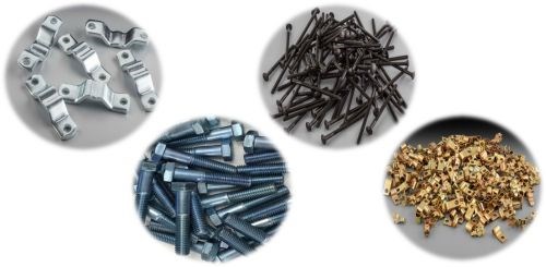
Figure 1 - Examples of passivate coating applications.
In the applications shown, the passivate is applied to an electroplated layer of zinc or zinc alloy on steel substrates. Specifically, zinc-nickel passivation is the focus here. This paper discusses the mechanism by which passivate films are colored as well as the development of a clear, colorless zinc-nickel passivate that achieves good corrosion protection.
Passivation overview
The development of trivalent chromium passivates has been ongoing for a number of years. The impetus has been the need to replace the traditional hexavalent chromium processes, which have been found to be toxic and hazardous to workplace safety and the environment.
In general, the chemistry of trivalent passivates for zinc and zinc alloy surfaces involves four ingredients:
- Cr(III) salt
- Ligand
- Corrosion inhibitor(s)
- Oxidizing agent
The trivalent chromium salts that have commonly been used in these passivates are chromium chloride [CrCl3], chromium nitrate [Cr(NO3)3] and chromium sulfate [Cr2(SO4)3]. Each ion has a different effect on the resulting passivate film. A study by Wen, et al.,† found that the anions functioned as pitting, oxidizing and passivating agents, respectively. Chromium sulfate chemistry produced the best results, forming a compact single-layered structure, while the other two tended to produce passivate layers with some degree of porosity.
The trivalent chromium ion in aqueous solution forms a hexa-aquo complex that is extremely stable, as shown in the structure in the left side of the reaction diagram in Fig. 2. For the Cr(III) to react to form the passivate layer, it must be able to break out of that complex and overcome its slow kinetics. This is accomplished with the introduction of a ligand. A ligand is an ion or functional chemical group that can bind to the central Cr(III), thus breaking the symmetry of the hexa-aquo complex. Installation of the ligand results in a complex that is less inert, producing a stable, yet labile complex that facilitates the formation of a passivation layer.

Figure 2 - Action of a ligand on a stable Cr(III) hexa-aquo complex, breaking its symmetry.
The nitrate anion is the most common oxidizing agent for zinc and zinc alloy passivation. The overall redox reaction that helps facilitate oxidation of the zinc or zinc alloy surface is:
NO3− + 4 Zn +10 H3O+ ↔ NH4+ + 4 Zn+2 + 13 H2O.
Lastly, the corrosion inhibitor is an additional reagent that enhances the corrosion protection of the passivate film. Common additives include triazoles, silicates, silanes and several transition metal ions, such as cerium, cobalt, molybdenum, nickel, titanium, vanadium and zirconium.
Figure 3 summarizes the passivation reaction. Immersion of the zinc or zinc alloy plated surface into the passivation solution results in a pH increase near the surface. This facilitates the ligand exchange and subsequent precipitation of the chromium. The incorporation of the other corrosion inhibitors is propelled through the Cr(III) precipitation.
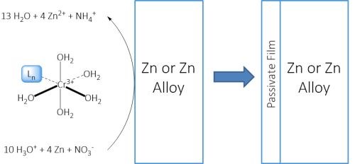
Figure 3 - Mechanism of Cr(III) passivation of an electroplated zinc or zinc alloy surface.
Passivation color mechanism
Imparting color to a passivate film is commonly accomplished via two methods: (1) dyes or (2) a thin film refraction effect.
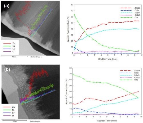
Figure 4 - SEM-EDAX and sputter depth profiling results for Cr(III) passivate coating immersion times of (a) 10 sec and (b) 60 sec, showing porosity developed over time (b).
The use of dyes is facilitated by the fact that passivate films are naturally porous. As the passivate film builds up over time, voids do develop, as shown in Fig. 4.†† Eventually, the developed voids will compromise the material and lead to poor corrosion resistance. Before reaching this point however, there is an optimum time, depending on the process, where sufficient thickness imparts good corrosion resistance and the pore density is not detrimental to performance. This porosity allows for dye adsorption, which produces a very intensely colored material (Fig. 5).
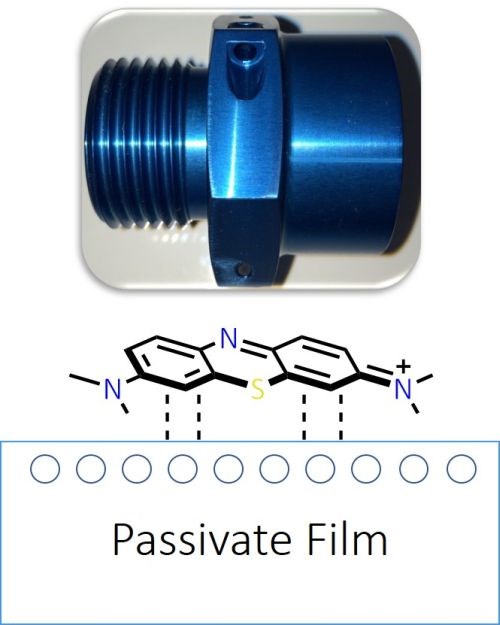
Figure 5 - (Top) Depth of color in dyed passivate film; (Lower) Adsorption of dye onto a passivate film.
The thin film effect, on the other hand employs the principles of light refraction found in nature such as is seen in an oil slick on a puddle of water. Passivate films can be colored by the same mechanism.
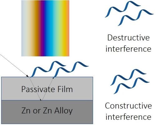
Figure 6 - The principles of the thin film refraction in creating colors in passivate films.
Passivate films are often transparent, and light can pass through them, but some of the light is reflected away from the passivate surface (Fig. 6). In the case of a clear passivate over an opaque zinc or zinc alloy substrate, the portion of light transmitted through the film is reflected back. If the combined light waves are in phase, constructive interference occurs. If they are 180° out of phase, destructive interference results in the reflected wave cancelling out the transmitted/reflected wave. Depending on the thickness and chemical composition of the passivate, certain frequencies on the light spectrum are cancelled and others are reinforced, and thus by thickness control, various colors can be produced. (Fig. 7). As well, the consistency of color indicates a uniform passivate film.
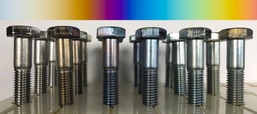
Figure 7 - Thin film effect in coloring of clear passivate films.
High-performance clear passivate
The goal of this work, utilizing the principles outlined above, was to develop a colorless to slightly colored
high-performance passivate for Zn-Ni coatings. The requirements were a thin film for color minimization, good long-term stability, superior corrosion protection and an easy-to-control two-component process system.
As noted above, the passivate color is a function of chemical composition and film thickness. For color minimization, the chromium complex was optimized for slower film formation, and the thinner film gave a pearlescent appearance.
Regarding bath stability, if the pH of the passivate solution is too low, then alloy loss or dezincification can occur during the passivation reaction. A low dissolution rate achieved by using a high pH will lead to an overall lower concentration of metallic contaminants. Accounting for the dragout rate, bath stability and performance should be long lasting.
The benchmark for superior corrosion protection is reached if the passivate coating readily achieves 240 hr of salt spray (ASTM B117) to first white rust (FWR). With this performance, the application of an added sealer can be avoided, if desired.
Our proprietary product utilizes a two-component process system. The nominal operating parameters are:

The importance of the chromium complex
As a final remark concerning the passivation process, the importance of the formed Cr(III) - ligand complex should be noted. Two sets of parts are shown in Fig. 8. These two sets of conduit clips were processed in almost exactly the same fashion. The first part in each set is the control (unpassivated), while the subsequent clips are passivated parts with increasing immersion times in increments of 15 seconds (15, 30, 45, 60, 75, 90 sec). The two processes used the same pH, temperature, immersion time for each case, Cr(III) concentration, corrosion inhibitor concentration and oxidizing agent concentration. The only difference between the two cases is the Cr(III) - ligand complex. The case on the right possesses a more active complex, which induces a thicker passivate film and results in visible film color. The left hand case has been optimized to provide a thinner film under identical treatment conditions as the case on the right. Thus, the chromium complex indeed matters.

Figure 8 - Effect of the nature of the Cr(III) - ligand complex on the passivate film.
Clear passivate corrosion resistance study
Starting with the nominal operating conditions noted above, a series of experiments were run to determine the effect of the various process variables on the corrosion resistance contributed by the trivalent passivate. The specimens were subject to salty spray for 264 hr.
Component A
In order to determine the effect of component A on corrosion resistance, samples were prepared varying the concentration of A from 3.75 to 10.0 vol% in increments of 1.25 vol%. Component B, pH, temperature and immersion time were maintained at the nominal values, as shown in the table in Fig. 9. The results for three of the Component A concentrations, 3.75, 6.25 and 8.75 vol%, are shown in the figure. Part number 27-35 serves as both a visual and corrosion testing control, as it is unpassivated. The results show some corrosion at 3.75 vol%, with good results at the higher concentrations, including 5.0 vol% (not shown). Higher concentrations do not provide extra protection and need not be considered.
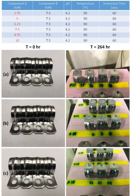
Figure 9 - Impact of component A on corrosion resistance: (Table) complete test matrix; (Photos) Salkt spray test results after 264 hr of exposure for passivate layers produced at (a) 3.75, (b) 6.25 and (c) 8.75 vol% of component A.
Component B
Similarly, for component B, samples were prepared varying the concentration of B from 2.75 to 9.75 vol% in varying increments, as shown in the table in Fig. 10. Component A, pH, temperature and immersion time were maintained at the nominal values, as in the Table. Part number 25-32 serves as both a visual and corrosion testing control, as it is unpassivated. The results for three of the Component B concentrations, 2.75, 5.50 and 8.25 vol%, are shown in the figure. Failure is noticeable at the two lower concentrations, indicating that the nominal 7.5 vol% provides a good result.
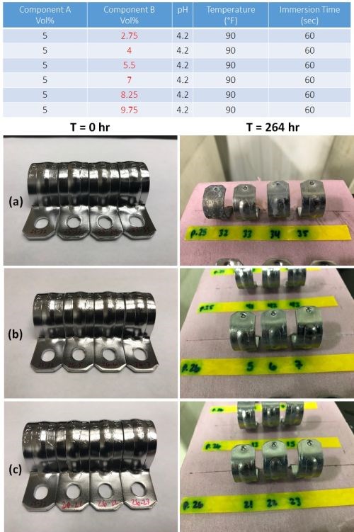
Figure 10 - Impact of component B on corrosion resistance: (Table) complete test matrix; (Photos) Salt spray test results after 264 hr of exposure for passivate layers produced at (a) 2.75, (b) 5.50 and (c) 8.25 vol% of component B.
pH
Samples were prepared varying the pH from 2.0 to 3.5 in increments of 0.5 pH, plus the nominal pH 4.2, as shown in the table in Fig. 11. Components A and B, temperature and immersion time were maintained at the nominal values, as in the Table. Part number 23-25 serves as both a visual and corrosion testing control, as it is unpassivated. The results for the five pH levels are shown in the figure. The pH 2.0 samples before test showed discoloration and corrosion failure is noted as well. The results at higher pH levels, including the nominal pH 4.2, are good.
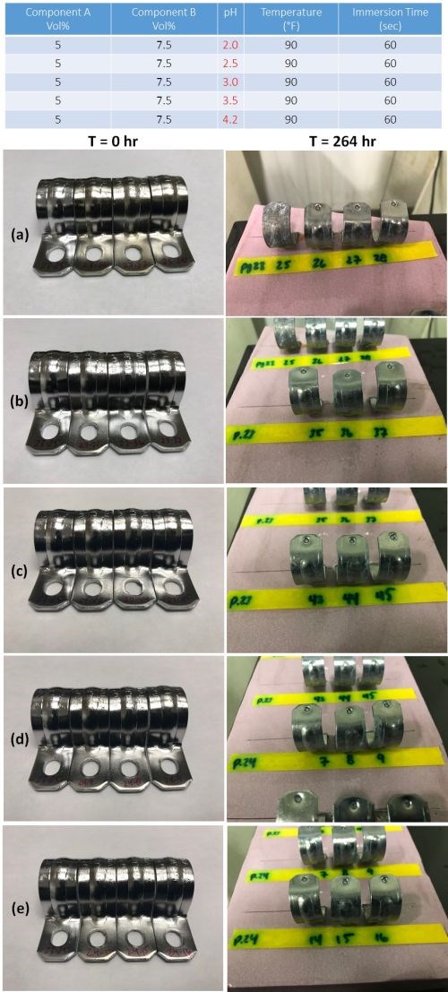
Figure 11 - Impact of pH on corrosion resistance: (Table) complete test matrix; (Photos) Salt spray test results after 264 hr of exposure for passivate layers produced at pH (a) 2.0, (b) 2.5, (c) 3.0, (d) 3.5 and (e) 4.2.
Temperature
Samples were prepared at 70, 80, 90 (nominal) and 100°F, as shown in the table in Fig. 12. Components A and B, pH and immersion time were maintained at the nominal values, as in the Table. The results are shown in the figure. Part 19-16 serves as a visual and corrosion testing control, as it is unpassivated. Failure is significant at 70°F and improving at 80°F. Corrosion results are good at 90 and 100°F.
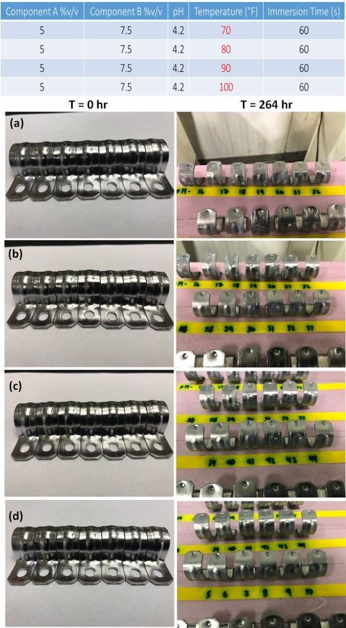
Figure 12 - Impact of solution temperature on corrosion resistance: (Table) complete test matrix; (Photos) Salt spray test results after 264 hr of exposure for passivate layers produced at (a) 70, (b) 80 and (c) 90 and (d) 100°F.
Immersion Time
Using the nominal process variables as shown in the table of Fig. 13, samples were prepared at immersion times from 0 to 90 sec, in 15-second increments. The results are shown in the figure for the regular 264 hr salt spray exposure, and for a significant extension to 936 hr. In both cases, voluminous white corrosion has not yet materialized. Thus, short immersion times can be used for this process to generate highly corrosion resistant passivation films.
.jpg;maxWidth=600)
Figure 13 - Impact of process immersion time on corrosion resistance: (Table) complete test matrix; (Photos) Salt spray test results after (b) 264 and (c) an extended 936 hr of exposure for passivate layers produced under nominal conditions.
Metallic contaminants
Over time, zinc contaminants can enter the passivate solution through reactant build-up from the plated coating, as well as iron from the underlying steel substrate where the zinc overlay is thin due to part geometry and other factors. Figure 14 (a-c) shows the effect of zinc contamination in the trivalent passivate solution after 744 hr of salt spray exposure for samples processed with zinc contaminant levels of 0, 5,000 and 10,000 ppm Zn. It be seen that the passivate appearance is negatively affected, as well as the corrosion resistance. The effect of 100 ppm of iron contamination is shown in Fig. 14(d), with similar results.
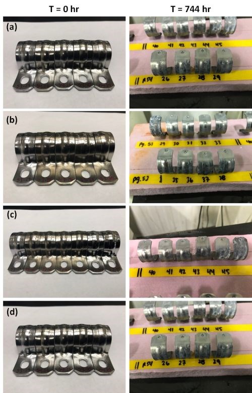
Figure 14 - Impact of metallic contamination on corrosion resistance: Salt spray test results after 744 hr of exposure for passivate layers produced with (a) 0, (b) 5,000 and (c) 10,000 ppm zinc contamination in the process solution, and (d) 100 ppm of iron contamination.
Summary
This paper describes a clear, colorless zinc-nickel passivate based on trivalent chromium chemistry that achieves good corrosion protection. A two-component system, it is simple to operate and offers good corrosion resistance over a wide range of process conditions.
About the authors

Mark Schario is Executive Vice-President at Columbia Chemical Corporation, headquartered in Brunswick, Ohio. He joined Columbia Chemical in 2010 as Vice President, Technologies and now serves as Vice President, Global Business Development for the company. He has over 30 years of experience in the surface finishing industry. Mark also functions as the company’s top liaison to the automotive industry and is Committee Chairman to ASTM B08 on Metallic and Inorganic Coatings which has jurisdiction over 132 standards. He is a member of the NASF and has earned the industry designation of CEF/Certified Electroplater-Finisher. Mark holds an Executive MBA from the Weatherhead School of Management at Case Western Reserve University.
*Compiled by Dr. James H. Lindsay, Technical Editor - NASF
** Corresponding author:
Mark Schario
Executive Vice President
Columbia Chemical Corporation
1000 Western Drive
Brunswick, OH 44212
Phone: 330-558-8184
Email: mark.schario@columbiachemical.com
† N.T. Wen, et al., Surf. Coat. Technol., 203 (3-4), 317-323 (2008).
†† H.H. Sheu, et al., Surf. Coat. Technol., 305, 241-248 (2016).
RELATED CONTENT
-
A Chromium Plating Overview
An overview of decorative and hard chromium electroplating processes.
-
Nickel Electroplating
Applications, plating solutions, brighteners, good operating practices and troubleshooting.
-
Masking for Surface Finishing
Masking is employed in most any metal finishing operation where only a specifically defined area of the surface of a part must be exposed to a process. Conversely, masking may be employed on a surface where treatment is either not required or must be avoided. This article covers the many aspects of masking for metal finishing, including applications, methods and the various types of masking employed.


