Choosing VOC Control Equipment
What you need to know...
Share
Oxidation, either catalytic or thermal,is a well-developed technology for VOC control. Although oxidation is not the only treatment available for controlling VOCs, it is advantageous because the pollutants are destroyed rather than captured. Other approaches to VOC control are condensation, adsorption, absorption and biofiltration. Oxidation units destroy nearly 100% of the VOC and toxic emissions targeted by the Clean Air Act Amendments (CAAA) of 1990. Depending on the type of system, destruction efficiencies of more than 99.99% can be attained. According to some sources, industry will spend more than $200 million on fume incinerators this year, which represents about 40% of all VOC control equipment.
The decades-old technology operates on a simple premise. Sufficiently heating a VOC consisting of carbon and hydrogen in the presence of oxygen reduces it to harmless carbon dioxide and water.
CzHy + (z+y/4)O2(z)CO2 + (y/2)H2O
In the reaction, the heat of formation of the products typically is less than that of the reactants, thus yielding a heat release. To initiate this reaction, a certain amount of energy is required. If the amount of energy released in the formation of the end products is greater than the amount required to initiate the reaction, the reaction will sustain itself without further input of energy. When a catalyst is used, the reaction remains the same, except the energy required to activate the reaction is lowered. Typical catalysts used are either precious-metal or metal-oxide based.
Sometimes the organic compounds in the waste air stream contain additional elements such as nitrogen, chlorine or sulfur. These elements create complications by adding extra products of combustion. When chlorine is present, the products of the general reaction will contain hydrochloric acid (HCl) and Cl2. The equilibrium concentration of Cl2 to hydrochloric acid can be approximated by the following equation.
InKp = 7048.7/T + 0.0151(1nT) - 9.06 x 10⁴ T - 2.714 x 10⁴T2 - 8.09 and
Kp = p(Cl2) x p(H2O)/p(HCl)2 x p(O2)½
Where units for temperature (T) are in degrees Kelvin and units for partial pressure (p) are in atmospheres (atm).
From this equation, it can be seen that the amount of Cl2 will decrease with increasing combustion chamber temperature. At times, it is better to have chlorine as HCl for easy scrubbing. Both compounds are undesirable in the exhaust stream, and an acid gas scrubber is usually required. The HCl is also cause for downstream corrosion, and materials of construction must be carefully selected.
If sulfur is present in the reactants, the equilibrium concentrations of SO2 and SO3 can also be approximated by the following equation.
InKp = 11196/T _0.362(1nT) + 9.36 x
10-4 T _ 2.969 x 10⁵ T-2 _ 9.88
Where Kp = p(SO3)/ p(SO2) x P(O2)½
At equilibrium, this equation suggests that the percentage of SO3 decreases with increasing oxidation temperature. In practice, however, SO3 is generally seen. Similarly, an acid gas scrubber is typically required downstream of the oxidizer.
As with any incineration process, the critical elements of successful thermal treatment are time, temperature and turbulence. This means the waste gas must be kept at incineration temperature for an adequate amount of time, generally 0.75 to 1 second. To destroy 98 to 99% of non-chlorinated VOCs, a thermal process will heat VOCs
to about 1,500F, whereas a catalytic system will heat the pollutants to about 700F. Factors influencing the temperature of an individual application include the chemical makeup of the VOC and oxygen availability. For some chlorinated hydrocarbons, the thermal incineration temperature can be in the 1,800F range.
The data in Table I was generated using kinetic theory, which assumes ideal mixing. However, this is not the case. Less than ideal mixing forces the design engineer to place a safety factor into the design oxidation temperature. As a measure of mixing, turbulent flow ensures adequate contact between process air and VOCs. Turbulence may be achieved in a variety of ways, such as using fluidized beds, stoneware, internal baffles, etc.
Applications for oxidizers include treating fumes from chemical/hydrocarbon processing operations, printing, paint finishing and coil coating. Oxidation units are often used with a plant's coating, drying and other processes.
Heat recovery
High-energy demands make heat recovery a must when treating high-flow, low-concentration air streams. Aside from whether they use an open flame or catalyst to oxidize VOCs, what sets oxidizer types apart is how they recover this heat. The oxidizer's approach to heat recovery usually is the limiting factor to the system's process applicability. An oxidizer that is highly efficient in capturing the heat will not be feasible for use with a gas stream that has a high amount of available energy when oxidized. In a similar fashion, a gas stream that has very little available heat when combusted will require a highly efficient heat recovery device for the oxidizer to be cost effective.
The two primary approaches to heat recovery are recuperative and regenerative. The recuperative exchanger transfers heat through a surface (heat exchanger tube, for example) from one fluid to another as long as a temperature gradient exists between the two fluids. In a regenerative system, a hot fluid transfers heat to the surface over time, after which the colder fluid is then passed over the same surface, absorbing heat from the surface.
Depending on the type of oxidation system and recovery design, as much as 95% of the thermal energy can be recovered to be reused in the oxidizer, other industrial processes or to provide building heat.
Afterburner
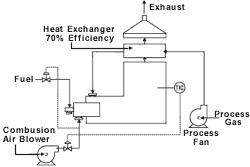
The typical afterburner consists of a burner, a burner train, a combustion blower and, if necessary, a process fan. Usually, this scheme is not used unless the concentration of the organic pollutants is elevated high enough to yield available energy to heat the products of combustion up to the chosen oxidation temperature. If the gas stream does not contain enough energy, then a burner is supplied to provide the necessary heat. Often, this type of system proves to be uneconomical from an operating cost basis, because of the high amount of gas used when oxidizing low concentration of VOCs in the gas stream.
Recuperative
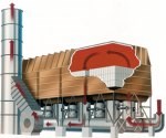
In a recuperative unit, the basic operation of the afterburner is retained except that much of the waste heat is captured. Because the system can capture this heat, it operates economically down to the 25% LEL range. In this type of system, a metallic-tube or plate-type heat exchanger is built into the exhaust end of the combustion chamber of the oxidation system. Typically, a plate exchanger is used when the exhaust gas stream does not contain elevated amounts of particulate and the maximum amount of heat recovery is desired. It is not unusual for a plate-type heat exchanger to be capable of achieving 70% heat recovery, while a tubular exchanger will recover 40 to 50% of the available heat. The heat recovery of a heat exchanger is defined as the amount of heat transferred divided by the maximum amount of heat that could be transferred.
Recuperative systems generally are smaller and lighter in weight than other oxidation systems, allowing for skid-mounted installations.
Recuperative systems work best with relatively high and stable VOC concentrations. Otherwise, auxiliary fuel is needed for air streams with little fume energy or for cyclical applications. With recuperative systems, high nitrogen oxide production may be a concern because typical designs allow for direct flame contact. Also, auto-ignition is possible in the tube or plate section of the heat exchanger where the gas stream temperature passes through the auto-ignition point of the organic compounds it contains.
Because of the metallic heat exchanger, recuperative systems are typically limited to operating temperature, below 1,400F, causing the process engineer to resort to increasing residence times and higher turbulence. When chlorinated compounds are encountered, acid-resistant refractories are needed. This increases the cost of the systems.
Catalytic
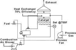
Catalytic oxidation systems are another option for low-VOC concentrations. These units are similar in design to recuperative units, except that solvents are oxidized using precious metal or metal-oxide-based catalysts instead of open flames. Operating at about half the temperature of thermal oxidizers, catalytic units have smaller footprints and relatively low operating costs.
| TABLE I | |||
| Compound Acrylonitrile Benzene Chlorobenzene Ethane Methane Methyl Ethyl Ketone Methyl Chloride Toluene Vinyl Chloride |
Auto-ignition Temperature(F) 800 1,044 1,180 959 999 960 1,170 997 882 |
T99.99 at 1 sec residence time 1,020 1,351 1,408 1,368 1,545 1,290 1,597 1,340 1,371 |
T99.99 at 2 sec residence time 975 1,322 1,372 1,328 1,486 1,247 1,514 1,295 1,332 |
Catalytic beds may be fixed, in which the catalyst is not allowed to move; or fluidized, with pelletized catalytic elements in a turbulent environment to allow greater contact between VOCs and the catalyst. Disadvantages of the catalysts are their susceptibility to poisoning, masking and high-temperature deactivation. Poisoning the catalyst consists of the reaction of the catalysts metal with some components of the gas stream (lead, for example). Masking is a process whereby the catalyst is coated with some inorganic material (sodium). A catalyst that has been masked can usually be cleaned and returned to service, while poisoned catalysts must be replaced. Elevated temperature also has a negative effect on catalysts. The thermal aging process of a precious-metal-based catalyst usually involves the migration of the well-dispersed, low-concentration precious metal from many activation sites on the surface of the catalysts to many fewer, higher precious metal concentration activation sites. In a metal-oxide-based catalyst, the mechanism usually involves the breakdown of the crystalline structure of the metal oxide. In general, precious metal catalysts have better elevated-temperature aging resistance than metal oxide catalysts.
Fixed or monolithic beds have more surface area for a given pressure drop than do the pelletized or fluidized bed catalyst systems that require less energy consumption.
A catalyst that uses a properly designed system may be effective for several years, but still may become coated and less effective through contact with compounds such as silicone, heavy hydrocarbons or particulates. Few catalysts can remain active in a chlorinated environment. Because of this, catalytic systems work best with relatively clean air streams having well-defined contents. Process upsets also must be scrupulously avoided to prevent damage to temperature-sensitive catalysts.
Breakthroughs in catalyst technology, however, continue to make catalysts more resistant to deactivation. A fluidized system using chromium-alumina catalyst beads is successfully treating chlorinated compounds in air streams from stripped groundwater at an Air Force Base in California. Trichloroethylene concentrations of 1 to 2 ppm are destroyed at 97.5% efficiency.
Regenerative
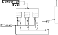
A regenerative system provides extremely high thermal-energy recovery. This process uses a ceramic heat-exchange bed to preheat process air to within 5% of the oxidation temperature. The ceramic bed typically consists of either structured or random packing. Historically, random packing has been used with 1-inch porcelain "saddles" being the most common media, but recently, structured packing in the form of honeycomb ceramic monolith has been used in many applications. The main advantage of the monolith media is its lower pressure drop derived from its greater void fraction and its inherent laminar flow characteristic. Saddle-based systems typically are lower in cost due to the mature market for ceramic saddles and their lower manufacturing costs.
Initially, the incoming process gas passes through a ceramic heat-recovery bed before entering the combustion chamber. It is during this step that the gas is preheated to within 5% of the combustion chamber temperature. After the process stream exits the ceramic bed, the already hot gases are further heated to the desired combustion chamber temperature. These gases are then sent through another heat-exchange bed where energy is absorbed and stored to heat the next cycle of contaminated air. Up to 95% of heat energy can be recovered with this multiple-bed approach. Low-VOC concentrations can be processed in a self-sustaining mode without burning extra fuel.
Regenerative systems are usually large and capital intensive, but recent trends and a competitive marketplace are reducing the size and cost. The typical bed velocity is between 200 and 250 fpm on a standard basis with random packing (gas volume referenced to 70F and 14.696 psia), or 300 to 350 fpm when structured packing is used. The typical pressure drop across a system is about 22 inches for a random-packed unit and 15 inches for a monolith-based unit.
Preventive maintenance and downtime are typically more extensive when hydraulic or electrically driven valves are used versus mechanically driven valves. The potential drawbacks of the large and capital intensive systems are offset by fuel savings, the ability to operate at high temperatures (2,000F) and high destruction efficiencies. Furthermore, with this process, a highly preheated waste stream's exposure to high-temperature flames is minimized, thus reducing concerns about NOx generation.
Regenerative systems are recommended for airflows typically above 10,000 scfm and solvent concentrations below about 10% LEL. For air streams with compounds that might build up in the heat recovery beds, regenerative systems can incorporate a bake-out feature to elevate bed temperatures and burn-off condensable organic compounds. Because of dependence on the sealing characteristic of the diversion valves, destruction efficiencies above 99% are possible but not typical.
Regenerative catalytic
A more recent addition to the oxidation technologies available to the process engineer is the regenerative catalytic oxidizer. This device is similar in operation to an RTO, but with a layer of catalyst in the combustion chamber. Both precious metal and metal-oxide-based catalysts are presently used. This technology has only recently been developed, with long-term success or failure still to be determined.
The net advantage of this type of unit is an additional reduction in operating costs by approximately 30%. These savings come from the decreased combustion chamber temperature and the reduction in pressure drop across the system.
This article discussed many basic concepts applied to the disposal of VOCs in process gas streams. The process engineer should understand the basic oxidation process reaction for organic compounds. Further, the impact of nitrogen, chlorine and sulfur should be considered in the oxidation of any process streams. From these concepts, the engineer can estimate the residence time, the necessary temperature and any special material of construction or emission concerns. Finally, the engineer should take into account the necessary heat recovery to make the system more economical and apply the correct type of oxidizer. Oxidation technologies are well understood and quite reliable. They dispose of the pollutant rather than transfer it.
Related Content
NASF/AESF Foundation Research Project #121: Development of a Sustainability Metrics System and a Technical Solution Method for Sustainable Metal Finishing - 15th Quarterly Report
This NASF-AESF Foundation research project report covers the twelfth quarter of project work (October-December 2023) at Wayne State University in Detroit. In this period, our main effort focused on the development of a set of Digital Twins (DTs) using the Physics-Informed Neural Network (PINN) technology with application on parts rinsing simulation.
Read MoreNASF/AESF Foundation Research Project #122: Electrochemical Approaches to Treatment of PFAS in Plating Wastewater - 12th Quarterly Report
This NASF-AESF Foundation research project report covers the 12th quarter of project work (October – December 2023) at the University of Georgia. In our previous report, we described our work on performance and effect of surface fluorinated Ti4O7 anodes on PFAS degradation in reactive electrochemical membrane (REM) mode. This quarter, our experiments involved utilizing porous Ti4O7 plates serving both as anodes and membranes. Tests compared pristine and F-18.6 Ti4O7 anodes at current densities of 10 mA/cm2 and 40 mA/cm2. This 12th quarterly report discusses the mechanisms of the effects on EO performance by anode surface fluorination.
Read MoreSMART Water: A New Wave in Water Management
Intelligent approach to water management leverages real-time data to optimize water as a strategic resource.
Read MoreExperts Team Up to Highlight Surface Finishing, Wastewater Solutions
SUR/FIN 2025: Hubbard-Hall and industry partners invite attendees over to learn about different product/technology offerings for surface cleaning, plating and wastewater treatment.
Read MoreRead Next
Reducing Material Use and Overspray
Looking for applicators or process improvements for reducing material use and overspray? Binks offers helpful advice for searching out new solutions.
Read MoreDelivering Increased Benefits to Greenhouse Films
Baystar's Borstar technology is helping customers deliver better, more reliable production methods to greenhouse agriculture.
Read MoreThe Best Tape for High-Temperature Applications
High-temperature tapes are designed with maximum heat ratings indicating the highest temperature they can withstand for a very short time.
Read More


