Loss Of Permeate Flux Rate
Question: We are experiencing loss of permeate flux rate.
Question:
We are experiencing loss of permeate flux rate. What might be the problem and how do we solve it? M.B.
Answer:
Permeate flux rate for anodic or cathodic electrocoat is a combination of physical and chemical properties. The physical properties are usually most important and are easier to monitor. Physical properties are mainly pressures and flow rates through or across the ultrafilter (UF) unit, regardless of the design of the UF. The flow rate of the pump is usually so large that it cannot be measured with a flow meter. Flow is usually calculated by pressure and/or pressure differential measured with pressure gages.
Featured Content
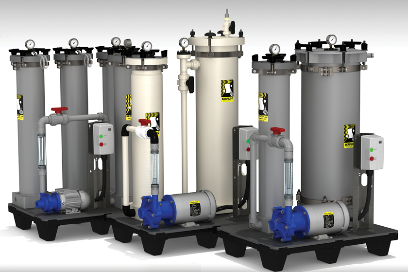
Pressure gages are critical to many parts of an electrocoat system and are very susceptible to plugging with paint solids. Three methods are used to improve the accuracy of pressure gages: 1) Use diaphragm-type filled gage protectors between the gage and paint flow; 2) Pipe gages as close to the paint flow as possible and/or with flow past the gage through smaller pipe back to the paint tank; and 3) (My preference) Use of "Pete's Plugs" at points where pressures are critical and use one "master gage" to take and compare readings.
Too much or too little pressure from the UF pump can affect the UF operation and the permeate flux rate. Make sure the equipment builder (or pump supplier), UF representative and paint supplier are all in agreement with the operating pressures to be maintained. This is especially critical if you are considering changing UF suppliers or designs. Quite often, pumps, valving, or pipe sizes need to be changed to optimize the UF operation.
Chemical parameters fall into three categories:
1. Paint solublizer (acid for cathodic and amine for anodic) levels and solvent levels are controlled by the paint supplier and the process control technician. They can be a major factor in flux rate and UF membrane longevity. Addition of these chemicals to the paint bath to achieve various quality/appearance requirements can affect the total VOC emissions and BOD in wastewater besides affecting the UF unit.
2. Paint bath contamination, usually from pretreatment chemical drag-in is the second major factor in fouling UF membranes and is harder to identify. Monitoring the final rinse prior to electrocoat at least twice (beginning and end) a shift or day is essential to identify a potential problem. Conductivity is the easiest way to identify a potential problem. As soon as a concern is identified, the rinse needs to be monitored as to the type of ions causing the high conductivity. This usually cannot be done by the in-plant lab and should be monitored by the suppliers.
3. Water supply, usually DI or RO, can also be a source of contamination. While most water generation units have automatic controls, lab monitoring should be done manually to make sure the automatic controls are working. Bacteria in the water supply are also a potential source contamination.
While paint, pretreatment, and water generation suppliers each have a responsibility in monitoring possible chemical contamination, make sure they do not "finger point" each other while you suffer. Get some independent testing and/or help before you get into expensive UF membrane replacement.
RELATED CONTENT
-
Five Principles of Lean Manufacturing from Toyota Production Systems
Fostering Sustainable business and People success through new ways of thinking
-
Building an E-coat Line from the Ground Up
How one company is prospering by providing flexible e-coat capability to Nissan and other customers.
-
Wireless Carrier Fleet Provides Modular Overhead Conveyance
Wireless, modular conveyor system provides flexibility and scalability for carrying parts through finishing processes.


