
NASF/AESF Foundation Research Project #123: Electrochemical Manufacturing for Energy Applications - 6th Quarter Report
The NASF-AESF Foundation Research Board selected a project on electrodeposition toward developing low-cost and scalable manufacturing processes for hydrogen fuel cells and electrolysis cells for clean transportation and distributed power applications. In this period, work focused on 3D printing anode support for solid oxide fuel cells, SOFC (or cathode for solid oxide electrolyzers, SOEC) based on our designed optimization outlined in the previous report.
#nasf #additive-manufacturing
Share
by
Majid Minary Jolandan*
Department of Mechanical Engineering
The University of Texas at Dallas
Richardson, Texas, USA
Editor’s Note: The NASF-AESF Foundation Research Board selected a project on electrodeposition toward developing low-cost and scalable manufacturing processes for hydrogen fuel cells and electrolysis cells for clean transportation and distributed power applications. This report covers the 6th quarter of work, from April to June 2023. A printable PDF version of this report is available by clicking HERE.
Featured Content


1. Introduction
Hydrogen has been identified by the US government as a key energy option to enable full decarbonization of the energy system.1 The US government has recently initiated a significant investment in the Hydrogen Economy, which is detailed in the recent “Road Map to a US Hydrogen Economy: reducing emissions and driving growth across the nation” report. In June 2023, the first ever “US National Clean Hydrogen Strategy and Roadmap” was published.2 On Nov. 15, 2021, President Biden signed the Bipartisan Infrastructure Law (BIL). The BIL authorizes appropriations of $9.5B for clean hydrogen programs for the five-year period 2022-2026, including $1B for the Clean Hydrogen Electrolysis Program. In alignment with the BIL and the mission of Hydrogen Energy “Earthshot” to reach the goal of $1 per 1 kg in 1 decade (“1 1 1”), the US is projected to invest in priority areas that will advance domestic manufacturing and recycling of clean hydrogen technologies.
Solid oxide electrolyzer cells (SOECs) are energy storage units that produce storable hydrogen from electricity (more recently increasingly from renewable sources) and water (electrolysis of water).3 The majority (~95%) of the world’s hydrogen is produced by the steam methane reforming (SMR) process that releases the greenhouse gas carbon dioxide.4 Electrolytic hydrogen (with no pollution) is more expensive compared to hydrogen produced using the SMR process. Investments in manufacturing and process development and increasing production scale and industrialization will reduce the cost of electrolytic hydrogen. Based on the recent DOE report, with the projected growth of the hydrogen market, the US electrolyzer capacity will have to increase by 20% compound annual growth from 2021 to 2050, with an annual manufacturing requirement of over 100 GW/yr. Given the complex structure and stringent physical and functional requirements of SOECs, additive manufacturing (AM) has been proposed as one potential technological path to enable low-cost production of durable devices to achieve economies of scale, in conjunction with the ongoing effort on traditional manufacturing fronts.5 Recently (2022), the PI published an article on challenges and opportunities in AM of SOCs,5 in which a comprehensive review of the state-of-the-art in this field is presented.
In this work, we aim to contribute to such effect of national interest to enable the hydrogen economy through development of manufacturing processes for production of low cost, durable and high efficiency solid oxide fuel cells (SOFCs) and SOECs.
2. Summary of Accomplishments (April-June 2023 Quarter)
In this period, we followed our work on 3D printing anode support for solid oxide fuel cells, SOFC (or cathode for solid oxide electrolyzers, SOEC) based on our designed optimization outlined in the previous report. We are currently optimizing the printing parameters, binder burn out and sintering to obtain printed parts with desired geometry and properties.
3. Activity
Initially, we started the 3D printing using pure resin to examine the size of the samples, their arrangement on the build plate, and their geometry for the planned flexure experiment. Figure 1 shows the results on printing pure resin. Figures 1(A) and (B) show 3D printed flat tube design SOFCs with pure resin on the printed built plate. Nine samples were printed at once. Figure 1(C) presents optical images that show the channels inside the support (left) and the cross-section print that shows the profile of the channels inside (right). Figures 1(D) thru (F) show various views of one of the samples on flexure test fixture. Overall, the initial result with the resin shows that several samples (up to nine) can be printed simultaneously, and that the designed geometry is appropriate for the planned flexure experiment.

Figure 1 - (A) and (B): 3D printed flat tube design SOFCs with pure resin shown on the printed built plate; (C) Optical images showing the channels inside the support (L) and the cross-section print showing the profile of the channels inside (R); (D) thru (F): Various views of one of the samples on the flexure test fixture.
In the next step, we moved forward with printing ceramic-loaded photocurable resin, in this case, 3YSZ. Since we use photopolymerization technique for 3D printing, the refractive index of the ceramic in the photocurable resin is an important factor. Table 1 shows the refractive index of various ceramics. The closer the refractive index of the ceramic material to the photocurable resin, the fewer the issues with refraction.
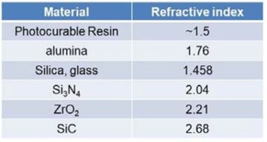
Table 1 - Refractive index of various ceramics.
For example, the refractive indices of alumina and silica are close to 1.5, and that is why these materials are rather straightforward in 3D printing by photopoly-merization. On the other end of the spectrum, the refractive index of SiC is ~2.68 and it also absorbs the UV light of the printer, which makes it nearly impossible to be printed by photopolymerization. For YSZ, yttria-stabilized zirconia, which is the material of relevance for SOFCs and SOECs, the refractive index is close to that of zirconia (~2.2), and there are significant issues with refraction. Hence, we needed to optimize our printing parameters.
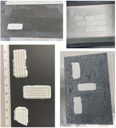
Figure 2 - Initial prints of 3YSZ ceramic.
Our initial prints were not successful, because of complications with the refractive index, which resulted in partial prints, or print layers failing to adhere to the build plate, instead of curing onto the vat film surface. Mid-print layer adhesion also proved problematic (Fig. 2).
After a series of process parameter optimizations, we successfully resolved most of these issues and were successful in obtaining prints with good quality. Figure 3 shows the first results on successful 3D printing of 3YSZ flat tube anode support concept. Figure 3(A) is the green body as printed. After printing, the resin in the print should be burnt off and then the remaining ceramic particles sintered to produce the final part. The binder burnout and sintering steps are critical and require extensive optimization. This is because, during binder burn out, volatile species are generated that must leave the part by diffusion.
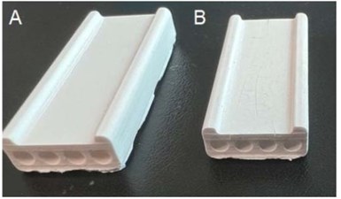
Figure 3 - (A) Green body 3D-printed 3YSZ anode support with integrated channels; (B) results of the first sintered samples.
If the burn out time-temperature profile is not optimized, the outgassing can generate delamination and cracks in the printed parts and compromise the integrity of the samples. Similarly, the sintering step is critical to obtaining a ceramic material without any obvious defects or delamination. Currently, we are working on optimization of the binder burn out and sintering processes.
4. References
1. Achieving American Leadership in the Hydrogen Supply Chain, US Department of Energy, 2022.
2. US National Clean Hydrogen Strategy and Roadmap, US Department of Energy, 2023.
3. A. Hauch, et al., “Recent advances in solid oxide cell technology for electrolysis,” Science, 370 (6513), p. eaba6118 (2020).
4. Hydrogen Generation Market Size, Share & Trends Analysis Report By Systems Type (Merchant, Captive), By Technology (Steam Methane Reforming, Coal Gasification), By Application, By Region, And Segment Forecasts, 2022-2030, Grand View Research, May 2022; https://www.grandviewresearch.com/industry-analysis/hydrogen-generation-market.
5. M. Minary-Jolandan, “Formidable Challenges in Additive Manufacturing of Solid Oxide Electrolyzers (SOECs) and Solid Oxide Fuel Cells (SOFCs) for Electrolytic Hydrogen Economy toward Global Decarbonization,” Ceramics, 5, 761-779 (2022); DOI: 10.3390/ceramics5040055.
5. Past project reports
1. Quarter 1 (January-March 2022): Summary: NASF Report in Products Finishing; NASF Surface Technology White Papers, 86 (10), 17 (July 2022); Full paper: http://short.pfonline.com/NASF22Jul1 .
2. Quarter 2 (April-June 2022): Summary: NASF Report in Products Finishing; NASF Surface Technology White Papers, 87 (1), 17 (October 2022); Full paper: http://short.pfonline.com/NASF22Oct2 .
3. Quarter 3 (July-September 2022) Part I: Summary: NASF Report in Products Finishing; NASF Surface Technology White Papers, 87 (3), 17 (December 2022); Full paper: http://short.pfonline.com/NASF22Dec2.
4. Quarter 3 (July-September 2022) Part II: Summary: NASF Report in Products Finishing; NASF Surface Technology White Papers, 87 (4), 17 (January 2023); Full paper: http://short.pfonline.com/NASF23Jan1.
5. Quarters 4-5 (October 2022-March 2023) Summary: NASF Report in Products Finishing; NASF Surface Technology White Papers, 88 (1), TBD (October 2023); Full paper: http://short.pfonline.com/NASF23Oct1.
6. About the Principal Investigator for AESF Research Project #R-123

Majid Minary Jolandan is Associate Professor of Mechanical Engineering at The University of Texas at Dallas, in Richardson, Texas, in the Erik Jonsson School of Engineering. His education includes B.S. Sharif University of Technology, Iran (1999-2003), M.S. University of Virginia (2003-2005), Ph.D. University of Illinois at Urbana-Champaign (2006-2010) as well as Postdoctoral fellow, Northwestern University (2010-2012). From 2012-2021, he held various academic positions at The University of Texas at Dallas (UTD) and joined the Faculty at Arizona State University in August 2021. In September 2022, he returned to UTD as Associate Professor of Mechanical Engineering. His research interests include additive manufacturing, advanced manufacturing and materials processing.
Dr. Minary is an Associate Editor for the Journal of the American Ceramic Society, an Editorial Board member of Ceramics journal and the current chair of the materials processing technical committee of ASME.
Early in his career, he received the Young Investigator Research Program grant from the Air Force Office of Scientific Research to design high-performance materials inspired by bone that can reinforce itself under high stress. This critical research can be used for aircraft and other defense applications, but also elucidates the understanding of bone diseases like osteoporosis. In 2016, he earned the Junior Faculty Research Award as an Assistant Professor at the University of Texas-Dallas – Erik Jonsson School of Engineering.
* Corresponding author:
Dr. Majid Minary Jolandan
Department of Mechanical Engineering
The University of Texas at Dallas
800 West Campbell Road
Richardson, TX 75080-3021
Office: ECSW 4.355H
Phone: (972) 883-4661
Email: majid.minary@utdallas.edu
RELATED CONTENT
-
Possibilities From Electroplating 3D Printed Plastic Parts
Adding layers of nickel or copper to 3D printed polymer can impart desired properties such as electrical conductivity, EMI shielding, abrasion resistance and improved strength — approaching and even exceeding 3D printed metal, according to RePliForm.
-
3D Printing for Masking
For liquid and powder coaters, the technology is a cost-effective option for producing custom masking in house.
-
Nanostructure of the Anodic and Nanomaterials Nanoparticles in Polyelectrolyte Multilayer-by-Layer (LbL) Films
Microstructure and elemental characterizations have indicated that the finish of a coating with a Layer-by-Layer (LbL) film results in a closely multilayered coating with a smoother surface. In this paper, the principles of assembly are discussed together with the properties of nanoparticles and LbL polymeric assembly essential in building hybrid coatings.


