
Nickel Electroplating
Applications, plating solutions, brighteners, good operating practices and troubleshooting.
#basics
Share
Nickel is plated for many reasons. First and foremost, nickel provides a decorative appearance because of its ability to cover imperfections in the basis metal (leveling). Nickel deposits can be made brilliant, and when covered by a thin layer of decorative chromium, will maintain their brilliance even under severe conditions. Satin nickel under bright or dark chromium offers a wide range of decorative appearances. When multi-layers of nickel are applied, excellent corrosion protection can also be achieved. This requires plating two (duplex) or more different kinds of nickel (semi-bright and bright nickel for duplex; high-potential and particle nickel). Nickel deposits also offer more wear resistance than softer metals such as copper or zinc, and thus can be used when wear resistance is needed. Because nickel is magnetic, it can sometimes be plated where the ability to be magnetized is needed. Finally, nickel can be made to plate with little or no stress and is therefore used for electroforming or aerospace applications where stress needs to be held to a minimum. Depending on the application, many of these requirements are specified simultaneously, so that nickel is often plated for more than just one reason.
Bright or satin nickel plating, used by itself or with other nickel deposits, is used extensively in automotive applications such as on plated wheels, bright trim, truck exhausts, bumpers and restorations. One or more layers of nickel is also used on motorcycles and bicycles, and on hardware such as hand tools. In the home, bright or satin nickel is used on plumbing fixtures, light fixtures, appliances and wire goods (racks). Nickel is also used for tubing applications such as on furniture and wheel chairs. Most of these applications for nickel/chromium rely on these deposits to achieve the part’s decorative appearance with corrosion protection and wear resistance.
Featured Content


Nickel is also used for engineering purposes where brightness is not the primary factor. For example, nickel is used on molds to provide wear resistance. As a barrier layer, nickel is plated on coins, jewelry and circuit boards. On strip steel and in aerospace applications, it is used for low stress or for resizing. Nickel is also used in composites where a dispersed inorganic is co-deposited (such as silicon carbide). Most engineering applications use sulfamate nickel, although nickel-plated strip steel uses a nickel chloride/nickel sulfate bath.
The most commonly used nickel baths are Watts baths, which use a combination of nickel sulfate and nickel chloride, along with boric acid. This combination of nickel salts allows for a variety of characteristics.
Watts Bath Components
A typical Watts bath contains nickel sulfate, nickel chloride and boric acid. Table I presents typical ranges for the components. Each component of the Watts formulation performs a very important and necessary role in the production of satisfactory deposits.

Nickel sulfate. Nickel sulfate is the source of most of the nickel ions and is generally maintained in the range of 20-40 oz/gal (150-300 g/L). It is the least expensive nickel salt, and the sulfate anion has little effect on deposit properties. Nickel sulfate is usually maintained at the high end of the range for very bright applications where throwing power (uniform thickness) is not a major consideration. It is maintained at the lower end of the range for applications where throwing power is needed, such as in barrel plating.
Nickel chloride. Nickel chloride is essential for good anode corrosion and improves the conductivity of the plating bath. The typical operating range is 4-20 oz/gal (30-150 g/L). A concentration of 4 oz/gal (30 g/L) nickel chloride is considered minimum for anode corrosion, unless special forms of anode material that contain nickel sulfide or nickel oxide are used as depolarizers. Low nickel chloride concentrations are used when throwing power is not a major consideration or when low deposit stress is required. This is especially true in semi-bright nickel plating where high chloride would yield a highly stressed deposit. High concentrations of nickel chloride are used when greater throwing power is needed and increased stress can be tolerated, such as in barrel plating.
Total nickel. This is an expression used for the combined nickel ions from the nickel sulfate and nickel chloride. A typical Watts formulation of 36 oz/gal nickel sulfate (22.3 percent nickel) and 12 oz/gal nickel chloride (24.6-percent nickel) would have 11 oz/gal (82 g/L) of total nickel. This concentration is generally adequate, but as current density requirements increase, the increased depletion rate should be offset by an increase in nickel ion concentration. The total nickel ion concentration is a significant factor in the limiting current density, or the point at which nodular or burned deposits become evident.
Boric acid. Boric acid buffers the hydrogen ion concentration (pH) in the cathode film. If it were not for this buffering action, the cathode film pH in the higher-current-density regions would quickly exceed 6.0, and nickel hydroxide would be precipitated and co-deposited along with hydrogen, resulting in a green nodulation or burned deposit. An indication of low boric acid concentration is the appearance of pitting or roughness in high current density regions. Boric acid, therefore, plays a very important role in establishing the upper limits of the applied current density.
Organic brighteners. In order to obtain the required physical properties, such as uniform bright deposit, it is necessary to add additives to a Watts bath. These are typically organic compounds that modify the nickel deposit to achieve a desired property. Brighteners for semi-bright nickel are designed to give a uniform nickel deposit where sulfur does not co-deposit with the nickel (see next section). Brighteners for bright nickel typically include a carrier additive, which adds sulfur to the deposit, provides ductility and gives a uniform grain structure. A secondary brightener is included that works with the carrier to provide a high degree of luster. Finally, in some formulations, a leveler is added to provide extreme brilliance through a leveling mechanism. It is critical that these organic components remain in balance; they are provided in proprietary packages from finishing suppliers. These packages are formulated to achieve the best combination of stability, brilliance, ductility and ease of use for various applications.
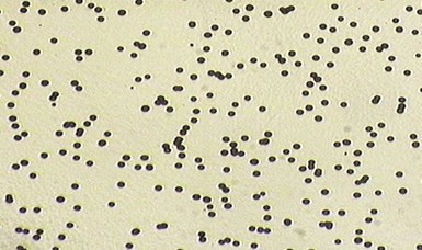
A – microporous chromium deposit
Bright and semi-bright nickel. Most nickel plating requires a long-lasting bright deposit, and, therefore, most applications use a chromium deposit over the bright nickel plating formulations given in Table I. However, bright nickel deposits contain enough co-deposited sulfur that they are more electrochemically active than nickel without sulfur, causing corrosion at an increased rate. In severe environments, this can lead to an early penetration of the bright nickel deposit and the subsequent rapid corrosion of the basis metal.
In order to solve this problem, a layer of nickel that does not contain sulfur can be deposited prior to the bright (or satin) nickel deposit. This sulfur-free deposit is called semi-bright nickel and is electrochemically less active than the bright nickel. The corrosion protection afforded to the basis metal is increased significantly by the use of the combination of bright and semi-bright nickel. The combination of plating a semi-bright nickel layer followed by a bright nickel layer is called “duplex” nickel with the semi-bright nickel layer typically at least twice as thick as the bright (or satin) nickel layer for best corrosion protection.
Special nickels for increased corrosion protection of the base material. The corrosion resistance of a duplex nickel deposit is greatly improved by the use of “special nickel” coatings. One such coating is a low-brightness bright nickel deposit on top of the bright nickel deposit that contains inert, non-metallic particles that co-deposit with the nickel and produces micro-pores in the subsequent chromium layer. The chromium plate does not completely cover the inert particles embedded in the nickel plate, producing a fine porosity in the chromium coating. This microporous chromium plate provides added corrosion protection because the corrosion cell spreads out over the entire surface, rather than being concentrated in local areas. Image A shows a top view of a typical porosity pattern in the nickel-chromium plate.
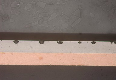
B – Cross-section of corrosion under microporous nickel
Image B shows a cross section of the corrosion in the bright nickel deposit under the micro-porous nickel and chromium deposits. Many specifications require a minimum of 10,000 pores/sq cm to obtain the enhanced corrosion resistance.
Micro-cracked chromium is another method to provide additional corrosion protection because the corrosion cell has spread out over the entire plate. Micro-cracked chromium is usually produced by using a highly stressed nickel plate on top of the bright nickel layer. Next, a thicker-than-normal chromium plate is applied to the highly stressed nickel layer, causing the high-stressed nickel and chromium deposits to uniformly micro-crack. The chromium thickness in the micro-porous layer is typically 0.25 to 0.5 microns of chromium, whereas the thickness of the chromium in the micro-cracked chromium is 0.8 or thicker. Micro-cracked chromium is not used very often because its appearance after corrosion is not as reflective as micro-porous systems. However, it can be more resistant to chemical attack when 1.2 microns or more of chromium is used.
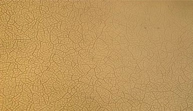
C – Microcrack chromium deposit
Image C shows a typical micro-cracked chromium pattern in the nickel-chromium plate. Many specifications require a minimum of 300 cracks/cm to obtain the enhanced corrosion resistance.
To improve the appearance after corrosion and the protection of the basis metal, a high-sulfur nickel layer (sacrificial deposit), is used. This nickel is co-deposited with 0.1-0.2 percent by weight sulfur and is deposited between the semi-bright and bright nickel deposits. The thickness is typically between 1.5 and 2.5 microns. In a part with a high sulfur layer, the initial corrosion occurs through pores in the chromium deposit into the bright nickel deposit until reaching the high-sulfur nickel layer. Once the corrosion reaches the high-sulfur nickel layer, the corrosion moves laterally between the bright and semi-bright nickel layers. This slows up the corrosion of both the bright and semi-bright nickel deposits.
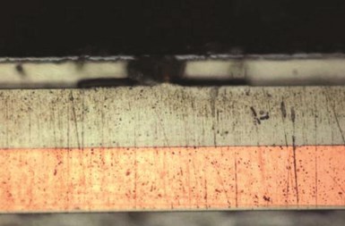
D – Cross-section of corroded high-sulfur nickel deposit
Therefore, the penetration through the semi-bright nickel layer is greatly prolonged, thus protecting the basis metal better than conventional duplex nickel deposit. Image D shows a cross section where the high sulfur layer is corroded laterally between the bright and semi-bright nickel layers. In both Images D and B, the corrosion sites are smaller in the deposits close to the surface. This reduces the loss of surface appearance by slowing up the formation of large visible corrosion sites.
For duplex nickel and the special nickels to obtain their best performance, all the deposits must meet many requirements such as STEP, porosity, ductility, thickness, etc. ASTM B 456 and ISO 1456 are good references for these requirements.
Watts Bath Operation
The operating conditions for almost all Watts-type nickel baths are similar. These typical parameters are given in Table II.
Levels of pH. Bright or semi-bright baths are generally operated between pH 3.5-4.2. Most organic addition agents give optimum brightness and leveling in this range. Higher pH values always present the danger of adverse effects from the precipitation of metallic contaminants and increased consumption of brightener components.
The pH should rise slowly during operation, since cathode efficiency is slightly lower than anode efficiency. Sulfuric acid should be used for pH adjustment, although hydrochloric acid may also be used with the added advantage of maintaining the chloride ion concentration.
However, the disadvantages of using hydrochloric acid include not only the higher amounts required but the escaping hydrogen chloride gas, especially from a hot, air-agitated solution.
Nickel carbonate is preferred for increasing the pH. It dissolves quite readily below a pH of 4.0. Very small adjustments to air-agitated solutions can be made below this value by adding a water-carbonate slurry while the tank is not in operation. Larger adjustments are best made in a treatment tank, followed by filtration. When increasing the concentration of nickel is detrimental, basic lithium salts, such as lithium carbonate, may be used.
During operation, if the pH requires no adjustment or if it decreases, look for anode problems. Insufficient anode areas, the overuse of inert auxiliary anodes, plugged anode bags or poor anode contact might be the cause. If not eliminated, these problems can quickly lead to salt depletion, poor plate distribution and off-color deposits from brightener decomposition. If the pH rises abnormally, it is rarely a cathode efficiency problem, provided the solution is in chemical balance. It is more likely that the acid is reacting with dropped parts, a portion of the tank wall or alkaline cleaner solution carried in on poorly maintained racks.
Agitation and temperature. Agitation and temperature increase the diffusion rate of ions into the cathode film. This is required in order to prevent burning and also to allow the additives to reach the cathode film.
Air agitation from a low-pressure blower has been universally accepted and is a contributing factor in many improvements in nickel plating, especially in the decorative area. Air agitation has broadened operating ranges of bath ingredients, reduced the required concentrations of addition agents and minimized the use of wetting agents and hydrogen pitting problems. Note that the use of air agitation will cause particulate matter to become suspended in the solution, resulting in rough deposits unless good filtration practices are used. Mechanical and/or eductor agitation can be used independently or in combination with air agitation.
The temperature range is important in terms of physical properties and, along with agitation, aids in keeping the bath components mixed, solubilized and functioning properly. If the temperature is too high, the addition agent consumption is increased, adding to the expense of operation and possible plating problems. If the temperature is too low, the boric acid will begin to precipitate and the additives might not respond efficiently.
Filtration. The value of adequate continuous filtration for prevention of roughness and pitting cannot be over-emphasized. Most bright nickel addition agents are not removed to any great degree by activated carbon. Therefore, good filtration over an activated carbon pack tends to keep concentrations of foreign organics, brightener decomposition products and particulate matter at a minimum.
A well-maintained, carbon-packed filter of adequate capacity tends to keep the physical properties of the deposit near optimum and minimizes the need for frequent batch treatments. It is better to apply smaller amounts of carbon at regular intervals over the normal repacking cycle than to add the total amount in one charge. This maintains the efficiency of the carbon pack by keeping fresh carbon on the surface and minimizing the tendencies of channeling of the solution through less restricted areas.
A suggested rate of use for carbon packing filters is 1-2 lbs. of carbon per 1,000 gal of nickel solution per 40-80 hr of operation. The rule of thumb is that the minimum hourly discharge rate of the filter should equal the volume of the solution. To achieve this with a carbon pack and as insolubles are collected, the filter should have two to three times the capacity in order to avoid frequent re-packings.
Troubleshooting Watts Baths
Roughness. Roughness is generally the result of particulate matter suspended in the solution and adhering to the work, especially on shelf areas. Gross roughness may be traced to improper cleaning, torn anode bags, airborne dirt, dropped parts, precipitated calcium sulfate, inadequate filtration, or carbon and filter aid from an improperly packed filter. A very fine type of roughness may be caused by precipitation of metallic contaminants in the cathode film where the roughness may be confined to a particular current density region. Chromium, iron and aluminum can precipitate as hydrates in the higher current density areas where the film pH is normally higher than that of the body of the solution. A lower operating pH may be helpful in such cases. On occasion, high current density roughness has also been traced to a magnetic condition of the work. Another source of roughness can be the air blower used for air agitation. Inspection of the filter on the air blower may reveal that it could be defective or missing, or the source of intake air is dirty.
If an external cause of roughness is not apparent, the quickest remedy is to pump the solution to a spare tank and inspect the plating tank. The cause may be apparent; dropped parts and torn anode bags are the most common sources.
Pitting. Pitting and fine roughness are easily confused unless viewed under magnification from several angles. Pits that are very round and bright are generally caused by hydrogen gas adhering to the surface during plating. Lack of agitation, excessive current density or a low boric acid concentration may be indicated. An addition of the supplier’s wetting agent may be helpful in these cases.
Dispersed air will give similar results and an indication may be a creamy appearance of the solution. Shut off the filtration and heat exchanger pumps and check for leaks in the intake piping and around the pump seal, which is the likely source.
Large, splotchy pits or pitted areas are usually an indication of grease or oil. This could be carried in on the work from poor cleaning or grease-contaminated acid dips, or it may be dripping from some piece of overhead equipment. Such contaminants are either liquid or semi-solids that may be dispersed to some degree by heat, agitation and wetting agents. Their presence may not be apparent on the surface of the solution. Some organic decomposition products, low-solubility additives and wetting agents may give a similar condition. In these cases, such gross contamination dictates carbon treatment and tank clean-out.
Small, irregularly shaped and spaced pits are likely to originate in the basis metal. Too often, additions of brighteners, wetting agents or acid are made before the basis metal is inspected. Look at several parts carefully and scribe any suspected areas prior to plating. All forms of pits and roughness typically have a negative impact on the corrosion resistance of the decorative deposits.
Adhesion. Poor adhesion appears in many forms: nickel from basis metal; nickel from nickel; or subsequent chrome plate from nickel plate.
Separation from the basis metal generally indicates that undesirable surface films are present and thus surface preparation has been inadequate. Poor cleaning may be caused by improper chemical maintenance and control of cleaners and acid dips; contamination and deterioration from prolonged use; poor rinsing; acid dips contaminated with copper, chromium or oil; or an inadequate process cycle for a particular soil or basis metal. Surface contamination will often be clearly visible or may be indicated by water breaks after rinsing. Cleaning problems generally involve much trial and error to identify their source. Try hand-scrubbing between and skipping certain operations, hand-precleaning or hand-dipping parts in buckets of fresh acid solutions.
If poor adhesion to the basis metal is traced to the nickel solution, severe contamination is indicated. Chances are that other problems such as poor ductility and stress will have given prior warnings. Of course, this does not rule out accidental spills and additions of wrong chemicals. Inadequate surface preparation such as with plastic, aluminum and zinc usually results in poor metal-basis metal adhesion.
Nickel peeling from nickel is commonly caused by complete or partial loss of contact during nickel plating. Total loss may result in an overall peeling condition. Momentary or partial loss creates a bipolar condition in which current flow is from the lesser negative (poor or no contact) rack to the more negative (good contact) rack adjacent to it, resulting in an anodic oxide film. This will normally be confined to one area, such as the trailing edges of parts plated in an automatic machine. Bipolarity toward the end of the nickel cycle may appear as though the chromium is coming off as a powder. A thickness check of the peeled versus the adherent portion will help locate the general area of the problem. If there is no clear pattern and the condition is intermittent, a faulty rack is indicated. Knowledge of bipolarity and other electrically related problems is essential in nickel and chromium plating.
Poor adhesion of bright nickel from semi-bright nickel or chrome plate from bright nickel, if not the result of electrical problems, can be caused by the nickel passivating during transfer. Long transfer times, drying of parts during transfer or warm rinses will increase the chances for nickel passivation. In these situations, the most common remedy is to activate the nickel prior to plating using an acid or acid salt.
Ductility and stress. Poor ductility and high stress are primarily an indication of poor maintenance of the plating solution. These properties are influenced by metallic and organic contaminants, improper chemical or brightener balance and, in some cases, additive decomposition products.
In all bright nickel processes, a balance of primary and secondary addition agents is required, as they function synergistically to maintain minimum stress and maximum ductility at the optimum degree of leveling and brightness. Many ductility, stress and chromium plating problems have been traced to out-of-balance secondary brightener levels.
Abnormally high voltages resulting from a lack of anode area may result in oxidation or chlorination of some organic additives, which may not be removed by carbon. Check all materials that are to come in contact with the solution, such as filter aids and anode bags, for soluble organics that may be harmful. Good housekeeping, solution control, continuous carbon filtration and periodic batch carbon treatments are essential to control ductility problems.
Dull deposits. Lack of brightness can be the result of rough base metal, poor cleaning, solution contamination, non-uniform agitation, improper chemical or brightener balance or failure to exercise proper control of operating conditions. A low pH or low temperature may cause an overall loss of brightness and poor leveling.
Loss of brightness in a particular current density may be the first clue to organic or metallic contamination. Dullness from poor cleaning or organic contamination may appear in any current density area. Metallic impurities generally exhibit their effects by either co-deposition in the low-current-density area or as hydrates in the high-current-density areas. Chemical analyses and plating tests will, in most cases, reveal the course of corrective action that should be taken if the problem is in the plating solution.
Metallic impurities. Copper, lead, zinc and cadmium, even in relatively small quantities (20-50 ppm), produce a dull, black or skip plate condition in the low current density areas. These metals may be removed by low current density dummy plating.
Phosphates, silicates, aluminum, trivalent chromium and iron all tend to precipitate in the high current density areas. Their presence can result in a hazy, fine roughness or burned appearance. Their effects will, therefore, be less pronounced at the lower value of the operating pH range. These elements are best removed by high-pH treatment. Iron must be oxidized to the ferric state with peroxide before it can be removed.
Iron contamination problems are minimized by the use of air agitation. Iron is oxidized by the air, precipitates around pH 4.0 and is removed by continuous filtration. A small amount of iron, precipitated in the body of the solution, appears to have far less effect on the deposit than when precipitated in the cathode film. However, lack of attention to dropped parts will result in frequent filter re-packing.
Iron and some other of the metallic impurities can be complexed to allow temporary relief from the problems associated with them. In the case of iron, control additives are available that allow the iron to be plated out in a controlled manner without seriously affecting appearance. In the case of other metallic contamination, proprietary additives are available to temporarily complex metallic impurities. However, the need for electrolytic purification still remains and must be performed at the earliest possible time.
Hexavalent chromium causes highly stressed and non-adherent deposits in the high current density areas. Its removal is best accomplished by reducing it to the trivalent state, followed by high-pH precipitation. A predetermined amount of sodium bisulfite is an effective reducing agent, and, after high-pH precipitation and filtration, a small addition of peroxide will oxidize traces of excess sulfite to sulfate. A brief period of dummy plating would then be in order. The most common sources of chromium contamination are poorly maintained racks and spray (from the chromium plating tank) that accumulates on the conveyer members. Mist from the chromium solution and chromium drippings from the rack coatings or the conveyer are common sources of blistering when they contact the work, particularly on copper, copper alloys and plastic.
Calcium contamination. Calcium contamination can cause problems at concentrations of about 500 ppm. Typically, the problem will be a fine roughness, which is often mistaken for pitting. If calcium contamination is causing the problem, its presence can be confirmed by shining a light through the hot (160°F) plating solution and looking for fine, needle-shaped crystals. Although the roughness could disappear when cooled, experience dictates that a removal treatment is needed. The preferred method is to precipitate calcium as the fluoride salt by the addition of 1.0-1.5 g/L of sodium bifluoride, followed by high-pH treatment and filtration. Calcium is not completely removed but is reduced to a more desirable level (100–200 ppm). Calcium problems are best avoided by using deionized water make up.
Phosphoric and nitric acids. Contamination from these acids is unusual but has occurred. Both acids cause an extremely stressed and non-adherent deposit at high current density and removal is difficult. High current density dummy plating is effective in remedying low levels of this contaminant, but severe contamination could require solution disposal
Purification of nickel solution. There has been so much progress in nickel plating, and especially bright nickel, that prolonged and frequent purification treatments are rare. A simple carbon treatment, which may include peroxide, is generally sufficient and can be performed at some convenient production interval. Continuous treatment with a resin unit can be performed while plating. When the need for purification is indicated and the cause of the problem is not readily apparent, chemical analyses and plating tests should always be performed to determine the best course of action. If the tests duplicate the plating results, the task is somewhat easier, but, if they do not, further investigation in other areas would be in order.
Too often, oxidation with peroxide or permanganate is tried without sufficient investigation. Commonly, one hears that these oxidizers “burn out” organics and oxidize them to carbon dioxide and water. In fact, sometimes the organic material is altered structurally, making carbon adsorption more efficient, or it may be oxidized to a more soluble form that has less deleterious effects on the deposit. But the oxidation could also result in a more soluble product that has a greater detrimental effect. Carbon (or resin) treatment is usually better as the first step. First carbon treat, then filter, then determine if an oxidization treatment is required.
Permanganate is a more powerful oxidizer than peroxide, but its use as a treatment must include increasing the solution pH to precipitate and remove the manganese dioxide. This, coupled with unreacted carbonate and carbon, may result in filtration difficulties and abnormal solution losses. To avoid using excess permanganate, which can result in serious loss of ductility and other deposit properties, dilute a 25–50 mL bath sample to 100–150 mL, adjust to a pH of 3.0–3.5, heat to 150°F and titrate with a standard permanganate solution to a pink endpoint. Calculate the amount of permanganate reacted; then try about one-half of this amount in the plating bath in the lab. This technique is also useful in checking the effectiveness of other organic removal treatments.
Several suppliers offer equipment that purifies nickel and dye-free acid copper plating solutions that operate like an ion-exchange unit. Like ion-exchange, this purification system can be regenerated giving the purifying material many years of useful life. These units can replace batch carbon treatments by keeping the plating solutions at the purity level of almost new solutions for optimum plating performance. Some of these purification units remove more organic contaminates than carbon (even with peroxide/permanganate) and some have additional columns to remove metallic impurities. A reduced but continuous filtration with carbon is still recommended.
Copper, lead, zinc, cadmium and some organics can be removed by low current density electrolysis. The most efficient current density may vary to some degree for each metal, but 2-5 asf of cathode surface can be tried first. Corrugated iron is ideal for cathodes, since it will provide a favorable distribution of current density. The pieces of corrugated iron should be as long as the plating rack and should be cleaned, pickled and nickel plated first at normal current density in order to avoid additional contamination of the solution being dummied. The cathode area should be as large as possible and good circulation or agitation of the solution should be employed. Inspect the cathodes for flaky or powdery deposits and occasionally raise the current density a few minutes as a seal. When finished, be sure to raise the current density again to seal in the contaminants. Frequent stripping of the dummy sheets or using new nickel-plated ones is important to not contaminate the solution.
RELATED CONTENT
-
Electroplating for Medical Devices
Brittany McKinney of Pavco Inc. discusses the benefits of electroplating for medical devices.
-
Engineered Coatings Offer Improvement for Medical Device Manufacturers
Diamond electroless nickel coating provides better lubricity and improved wear resistance for molds, resulting in better quality and productivity.
-
How to Maximize Nickel Plating Performance
The advantages of boric acid-free nickel plating include allowing manufacturers who utilize nickel plating to keep up the ever-changing regulatory policies and support sustainability efforts.


