Electrodeposition of Ni-Fe-Mo-W Alloys - Part 1
1st Quarterly Report - AESF Research Project #R-117
This paper was submitted to NASF and the AESF Foundation Research Board in April 2013 as a 1st-quarter report of AESF Research Project #R-117.
#research #nasf
by E.J. Podlaha-Murphy, Professor of Chemical Engineering, Northeastern University
Editor's Note: This paper was submitted to NASF and the AESF Foundation Research Board in April 2013 as a 1st-quarter report of AESF Research Project #R-117. A printable PDF version is available by clicking HERE.
Featured Content
Introduction
This project addresses the induced codeposition of molybdenum and tungsten alloys with nickel and iron with a focus on developing a toolbox of plating conditions to deposit different combinations of Ni, Fe, Mo and W. The experimental approach will utilize electrodes with a controlled hydrodynamic environment, since it has been noted by the project director that the reduction mechanism can involve a coupled kinetic-mass transport behavior. The project was initiated in January 2013 and as of April 15, 2013, we have started three different sub-projects, in parallel, utilizing a Hull cell, a rotating Hull cell and a rotating cylinder electrode.
Sub-project #1:
Matthew E. Silva, undergraduate senior in chemical engineering
Mathew Silva is a senior undergraduate student at Northeastern University participating in this research for one semester through a research course, CHME 4991- sec 01, “Research.” He has surveyed conditions where the morphology of NiMoW looks metallic at different electrolyte temperatures over a wide range of current densities employing a rotating Hull cell (Fig. 1).
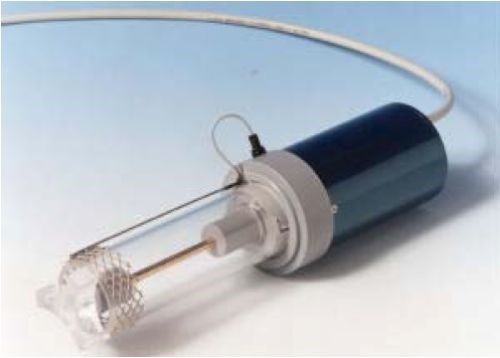
Figure 1 - Rotating Hull cell (Eco-Chemie, Utrecht, The Netherlands; http://www.ecochemie.nl/).
The electrodeposition of NiW and NiMo alloys are typically carried out in ammoniacal electrolytes, as the addition of ammonia tends to increase current efficiency, although at a cost of lowering the amount of tungsten or molybdenum in deposits. Recent literature reports on NiW1-3 electrolytes that do not contain ammonia, but which retain a relatively high current efficiency (>50%) has motivated the work here.
The NiMoW electrolyte under consideration contained 0.15M nickel sulfate, 0.1M sodium tungstate, 0.1M sodium molybdate, 0.375M sodium citrate and 1.0M boric acid. The pH was adjusted with dilute sulfuric acid or potassium hydroxide to maintain a value of 7.0-7.3.
Rotating Hull cell experiments at 500 rpm were conducted for three average applied current densities (1.0, 2.0 and 3.0 A) and three temperatures: room temperature, 40°C and 60°C. The electrode area was 15.1 cm2. Figure 2 shows several samples positioned next to a normalized current distribution scale, ix/iavg. The scale is based on a primary current distribution assumption that is valid only when the Wagner number is small <1. The rotating Hull cell experiments at an average applied current density of 1.0 A, (iavg = 66.3 mA/cm2) show a smooth silver/matte deposit at the high current range ix ~ 130-200 mA/cm2, with very little deposition occurring in the lower current density range, ix ~ 7-33 mA/cm2. At lower temperatures the deposit occurs over a broader length of the electrode at lower current densities, while higher temperatures show an apparent shift in the deposit to the higher current density regions observed in each of the applied currents.
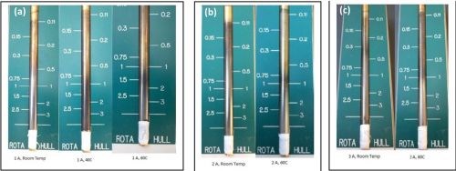
Figure 2 - Rotating Hull cell working electrodes, (a) iavg = 1.0 A at room temperature, 40°C and 60°C; (b) iavg = 2.0 A at room temperature and 60°C; (c) iavg = 3.0 A at room temperature and 60°C.
In order to determine if the rotating Hull cell indeed creates a current distribution, the Wagner number,
(1)
needs to be considered, where K is the solution conductivity, is the inverse slope of a polarization curve with uniform current distribution with the same mixing environment and L is the electrode length. In this study, the electrode length in contact with the electrolyte was 8.0 cm. In order to determine the derivative, the polarization curve was measured and the potential was corrected for ohmic drop by impedance spectroscopy.
Linear sweep voltammetry was conducted using a Solartron SI 1287 instrument. A platinum mesh anode was used as a counter electrode and a saturated calomel electrode was used as a reference. The rotation rate of the working electrode was constant at 500 rpm for each scan. Voltages were swept from -0.1 VSCE to -5.0 VSCE at a rate of 2 mV/sec. A Solartron 1252A frequency response analyzer was used for electrochemical impedance spectroscopy (EIS). Frequencies were generated from 1Hz-100kHz. Resistance values were obtained by extrapolation to obtain the real component of the impedance at high frequency.
Figure 3 shows the polarization curves corrected for ohmic drop at room temperature, 40°C and 60°C. Inspection of the slope of the polarization curves at the high current density end shows that there is not a large change in slope with temperature. The value of ~ 0.41 A/cm2/V was obtained. Assuming the solution conductivity to be close to water, κ = 0.01/Ω•cm. The dimensionless Wa number is:
(2)
a value sufficiently low (<<1) that primary current distribution should prevail and the green scale bar in Fig. 2 is a good measure of the dimensionless local current, ix/iavg.
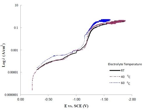
Figure 3 - Polarization curves corrected for ohmic drop at room temperature, 40°C and 60°C.
Sub-project #2:
Shaopeng Sun, Ph.D. graduate student
We examined the DC deposition of NiMoW alloys at room temperature for another grant (NSF Chemistry Division) using a similar citrate electrolyte, and found that, with equimolar molybdate and tungstate in the electrolyte, there was always more molybdenum in the deposit regardless of the applied current density. As part of this NASF/AESF Foundation grant, we will examine the pulse deposition of NiMoW alloys to see if we can alter the Mo:W ratio of the resulting deposit.
Pulse deposition of molybdenum and tungsten alloys are motivated by reports that pulse waveforms can affect the resulting deposit composition4 and morphology.5 In NiMo4 and NiW6 systems, pulse deposition can also increase the current efficiency when compared to direct current. The seminal work by Marlot, et al4 showed that the wt% of molybdenum in the deposit increased at high frequency and low duty cycle when compared to DC deposition. This was attributed to the increase in the limiting current density of molybdenum as a result of pulsing from an ammoniacal electrolyte that contained a higher concentration of Ni(II) than molybdate ions.
The electrolyte considered in our work contained 0.075M sodium tungstate, 0.005M sodium molybdate, 0.1M nickel sulfate, 0.375M sodium citrate and 1.0M boric acid. The pH was adjusted by sodium hydroxide or sulfuric acid to 7.0. No ammonium species were present in the electrolyte. A rotating cylinder electrode with uniform current distribution was used as the working electrode and the rotation rate was constant at 517 rpm. Frequency and duty cycle were varied for galvanostatic pulsing with an “on” deposition current density of -10 mA/cm2 and a zero “off” current density.
Figure 4 shows the potential transients for three different “on” times of 0.01, 0.1 and 1.0 sec. The length of the “off” or zero current time was varied to keep the duty cycle, , constant at 0.8, 0.5 and 0.25, respectively. Deposits were obtained in all cases that were shiny grey and bright.

Figure 4 - Pulsed deposition of NiMoW onto rotating cylinder working electrodes, with three different duty cycles (0.8, 0.5, 0.25) and with three different “on” times (a) 0.01 sec, (b) 0.1 sec and (c) 1.0 sec.
At a given duty cycle [black curves in Figs. 4(a,b,c)], the deposition potential is nearly insensitive to a change in the “on” time, or in other words, frequency. The faster the pulsing the greater the change in the deposition potential with duty cycle [e.g., compare the first pulse potential in Fig. 4(a) vs. 4(c)]. The steady state DC current efficiency is low (~10%) so that the potential transient is reflecting a generous amount of the hydrogen evolution side reaction. It is expected that during deposition adsorbed hydrogen is created and that during the transient some of the adsorbed hydrogen may be desorbed.
The deposit composition was analyzed by x-ray fluorescence (XRF). Figure 5 is a plot of the deposit composition, in weight percent of Mo, Ni and W when pulsed at a duty cycle of 0.5. Also superimposed on this figure is the DC steady state composition. For different pulse frequencies, , the deposit composition did not change significantly. This is consistent with the relatively constant potential during the “on” pulse in Fig. 4 [black curves in Figs. 4(a,b,c)]. Compared to the non-pulsed DC case, there is a considerable change in the deposition composition. Most notable is that the amount of molybdenum decreases when pulsed and both the amount of nickel and tungsten go up almost proportionally. This hints that hydrogen may be playing a role in favoring molybdenum.
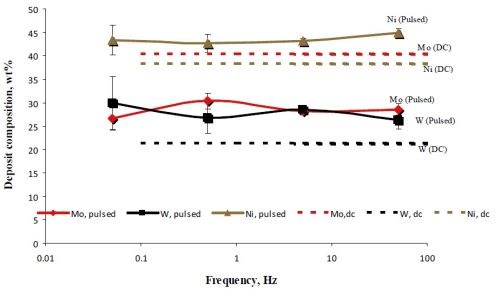
Figure 5 - A comparison of the NiMoW deposit alloy composition when electrodeposited under DC conditions, 10 mA/cm2 and under pulsed current deposition with the same current density.
The other significant effect that is observed in the potential transients in Fig. 4, is the change in the deposition potential when the “on” time is short, 0.01 sec. Table 1 reports the deposit composition. As the duty cycle increases, the deposition potential becomes more negative and the composition is altered. An increase in duty cycle, with a longer “off” time, decreases the molybdenum content in the deposit and significantly increases the tungsten content.
Table 1 - Deposit composition data corresponding to Fig. 4(a), with different duty cycles.
|
“On” |
“On” |
“Off” |
“Off” |
Duty |
Wt% Mo |
Wt% W |
Wt% Ni |
|
10 |
0.01 |
0 |
0.03 |
0.25 |
35.0 ± 2.8 |
19.3 ± 2.3 |
45.7 ± 2.8 |
|
10 |
0.01 |
0 |
0.01 |
0.50 |
28.6 ± 1.1 |
26.4 ± 2.0 |
45.0 ± 0.9 |
|
10 |
0.01 |
0 |
0.0025 |
0.80 |
26.5 ± 0.3 |
32.0 ± 0.4 |
41.4 ± 0.6 |
A part of this work was presented at The Electrochemical Society in Toronto, CA, this past May 2013. Funding from the NASF and AESF Foundation was acknowledged. A proceedings publication was planned in the ECS Transactions.
Sub-project #3:
Avinash Kola, starting Ph.D graduate student
As part of this NASF/AESF Foundation grant, we will investigate different additives and complexing agents, targeting combinations of NiFeMoW. As a starting point, NiW deposits were electrodeposited from a conventional Hull cell, using a non-ammoniacal citrate electrolyte. Figure 6 shows the Hull cell that was used, with air flow agitation. The effect of a thiourea additive on NiW deposition has been initiated. Thiourea has been noted to influence metal electrocrystallization7 and hence affect morphology, although the inclusion of sulfur may be detrimental to corrosion resistance.
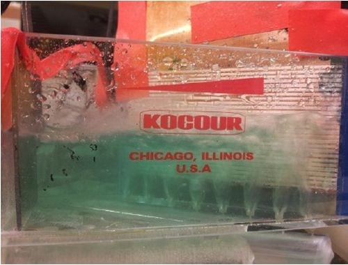
Figure 6 - Conventional Hull cell with air flow agitation.
The electrolyte used contained: 0.05M nickel sulfate, 0.015M sodium tungstate, 0.285M sodium citrate, with 0.65M thiourea at a pH of 2.0. Deposits were obtained using an average applied current, iavg = 0.1 A at pH 2.0 with and without thiourea at different air flow rates. There was a noticeable change in the current density region where deposits were obtained with and without thiourea.
Polarization curves were obtained from this electrolyte under the same mixing environment as the Hull cell (Fig. 7). When thiourea is eliminated from the electrolyte there is an increase in the current density for a given potential.
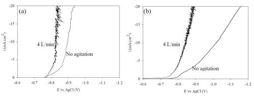
Figure 7 - NiW polarization curves (a) with and (b) without the addition of 0.65M thiourea, air flow agitation; 4 L/min and 0 L/min.
Overall Summary
Three students participated in the NASF/AESF Foundation research this quarter and the same three continued over the summer months. Different aspects of the alloy deposition project are being considered in parallel, with experiments utilizing Hull cells, investigation of the effect of additives, and pulse deposition, all from a more environmentally friendly, non-ammoniacal electrolyte. We have focused on the NiMoW and NiW systems in this quarter with interesting results:
- NiMoW electrodeposited at higher electrolyte temperature required higher current densities to achieve a deposit;
- Pulsed deposition of NiMoW resulted in a change of deposit composition and
- The total polarization of NiW electrodeposited with a low pH electrolyte was depolarized with a thiourea additive.
References
1. M. Zemanová, R. Kurinec, V. Jorík & M. Kadlečíková, Chemical Papers, 66 (5), 492 (2012).
2. M.D. Obradović, J. Stevanović, A.R. Despić, R. Stevanović & J. Stoch, J. Serb. Chem. Soc., 66 (11-12), 899 (2001); http://www.shd.org.rs/JSCS/Vol66/No11-12/V66-No-11-12-15.pdf.
3. I. Mizushima, P.T. Tang, H.N. Hansen & M.A.J. Somers, Electrochim. Acta., 51 (27), 6128 (2006).
4. A. Marlot, P. Kern & D. Landolt, Electrochim. Acta., 48 (1), 29 (2002).
5. S. Lee, M. Chang & J. Lin, Corros. Prev. Control, 46 (2), 71 (1999).
6. M. Zemanová, M. Krivosudská, M. Chovancová & V. Jorik, J. Appl. Electrochem., 41 (9), 1077 (2011).
7. H. Cao, et al., J. Solid State Electrochem., 16 (9), 3115 (2012).
RELATED CONTENT
-
Electroplated Tin-Nickel Coatings as a Replacement for Nickel to Eliminate Nickel Dermatitis
This paper is a peer-reviewed and edited version of a paper delivered at NASF SUR/FIN 2013 in Rosemont, Ill., on June 12, 2013.
-
NOx Scrubbing Technology Breakthrough
This paper presents research findings and practical results that address the treatment of the problematic greenhouse gases nitrogen oxides (NOx) and sulfur dioxide (SO2).
-
An Improvement in the Zincate Method for Plating on Aluminum
Investigations were conducted into the sodium zincate solution used for treating aluminum prior to its being plated. Measurements of the adhesion of the nickel plate to aluminum and its alloys were done to check the effect of modifications made to this solution.


