Improved Process Capabilities for Groove Repair
Advanced selective plating techniques have been developed for the challenging application of repairing internal grooves that have experienced severe corrosion. Many groove configurations require uniform, high-thickness deposition of a plated deposit onto any, or all, of the surfaces with a minimal need for intermediate machining steps. This paper demonstrates how a combination of an engineered, wrap-less anode design along with optimized computer controlled operating parameters has led to reduced downtime, high quality and repeatable selective plating repairs.
#research #surfin
Editor’s Note: The following is a synopsis of a presentation given at NASF SUR/FIN 2019, in Rosemont, Illinois on June 5, 2019 in Session 14, Advancing Technology Applications for Finishing/Engineering Opportunities. A pdf of this brief can be accessed and printed HERE; the complete Powerpoint presentation is available by clicking HERE.
ABSTRACT: Historically, selective plating has been a manual process dependent on the skill of the operator. By optimizing the process and equipment, operators can achieve consistent, uniform deposits for a variety of challenging applications including the repair of internal grooves. Advanced selective plating techniques have been developed for the challenging application of repairing internal grooves that have experienced severe corrosion. Many groove configurations require uniform, high-thickness deposition of a plated deposit onto any, or all, of the surfaces with a minimal need for intermediate machining steps. This paper demonstrates how a combination of an engineered, wrap-less anode design along with optimized computer controlled operating parameters has led to reduced downtime, high quality and repeatable selective plating repairs. This presentation reviews the stages of developing the selective plating process for plating grooves from manual operation to an automated process. Through case studies of different groove applications, we demonstrate how selective plating can be used for repair or for OEM applications to apply engineered deposits in internal grooves for dimensional repair and to provide corrosion protection.
Featured Content
Introduction and background
Selective plating was originally developed in 1938 in Paris, France by George Icxi. It basically evolved from the simple touch-up of tank plated parts. In 1959, the Steel Improvement and Forge Company (also known as SIFCO Industries) bought a Canadian-based firm and moved all operations to Cleveland, Ohio. In 2012, SIFCO was acquired by Norman Hay, headquartered in the UK. NH was originally founded in 1940 doing chromium plating and hard anodizing.
In this presentation, the concept of selective plating will be discussed. Focusing on grooves, we define the term “groove” quite broadly. A number of different configurations that are used on machined components will be considered in terms of the kinds of damage they can be subjected to and the various repair options that are available. The most common deposits used for groove applications and their properties are covered. Finally, the challenges faced when electroplating a groove, how they can be managed, and examples of component repairs round out this paper.
Selective plating concepts
Selective plating, or more commonly brush plating, is a portable process for plating localized areas on a workpiece without the use of an immersion tank. There are four key elements to a brush plating set-up, shown in Fig. 1:
- The workpiece, in this case is the inner diameter of a cylinder that is being rotated by a turning head fixture on the right.
- The power pack, with current, voltage and amp-hr control, on the left.
- The plating tools, the anode here inserted into the hole in the workpiece, and
- The preparatory and plating solutions, contained in the tank in the solution flow system, center.
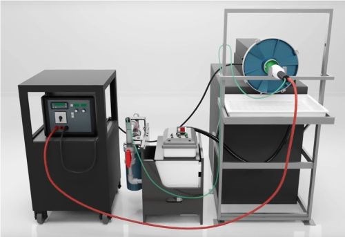
Figure 1 - Typical setup for selective / brush plating.
The anodes can consist of graphite, Dura-A-Form®, platinum, or platinum-clad niobium or titanium. They are typically made to conform to the substrate to optimize thickness distribution. The red and black cables connect the power source to the anode and workpiece, and the green and black tubing provide solution circulation between reservoir and workpiece.
The rest of operation decisions are based on whether you need to heat, flow or dip the plating solutions, how the workpiece is to be masked to define the selected area and whether any auxiliary equipment is needed to hold or rotate the part and/or or the plating tools.
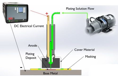
Figure 2 - Selective plating operation.
As shown in Fig. 2, an electrolyte containing metal ions is introduced between a positively-charged anode (i.e., the preparatory or plating tool) and a negatively-charged cathode, i.e., the workpiece. The anode itself is wrapped with a material that can be made of cotton, PermaWrap® or red or white TuffWrap®, etc. The wrap serves two main functions: one is to prevent an anode to cathode short-circuit; the second objective is to act as the carrier for the solution which helps facilitate the current flow by wetting both electrodes in order to create the electrochemical cell. The solution can be introduced to the workpiece one of two ways, either by flowing the solution through the anode using an external pump or by dip plating, where the anode is dipped into a beaker sitting near the workpiece.
A typical plating scheme consists of several preparatory steps that prepare the surface for the final metal deposition step. Each prep step requires a dedicated anode. The prep steps usually entail an electroclean, etch, desmut and activation of the surface of the workpiece. The part is also rinsed in between steps with water in order to avoid cross contamination and assure a clean work surface. After the workpiece has been properly prepared, a nickel preplate (in most cases) is applied, the choice depending on the substrate material.
Selective plating can be applied to the full range of metal substrate materials used in industry today. The area to be plated is isolated, using masking tapes, paints, or fixtures. Because the part to be plated is not immersed, only minimal masking is needed to protect adjacent areas.
A plating tool (or anode) that conforms to the shape of the part is typically made of insoluble materials. The plating tool is wrapped with an absorbent cover material that insulates the plating tool from the part as it is moved over the area to be plated and uniformly distributes the plating solution on the work area.
The plating solution that carries the metal to be deposited on the part is pumped to the work area, through the anode and cover material and is recirculated. Electrical current is provided by a rectifier that can be operated manually or programmed to control the polarity, voltage, amperage and ampere-hours.
Selective plating requires consistent movement between the plating tool and the part. The metal contained in the plating solution is uniformly deposited onto the part with the thickness being controlled by ampere-hours, or total electrical charge passed.
Compared to tank plating, brush plating is 40 to 60 times faster. The average current density for tank plating is typically 0.10 to 0.25 A/in2 (14.4 to 36 A/ft2), whereas brush plating current densities can range from 1.0 to 6.0 A/in2, depending on the specific plating solution in use.
Combining the effects of high metal concentrations, high solution replenishment and the brushing action or speed of the anode, the hydrodynamic boundary layer at the surface of the workpiece is significantly reduced, allowing us to push the limiting current densities and plate significantly faster. The various wrap materials also act to help level the deposit as it builds, allowing for more control over the application. All of these features together, allow easily controlled applications of the coating just where it is needed on the part.
Brush plating is widely accepted in both military, commercial and industrial applications. Much of the development work was done in the 1960s and 1970s with the military. Two key specifications are Mil Std 2197, which is a navy specification, and Mil Std 865 which is an air force specification. In the case of anodize coatings, Mil A 8625 is typically referenced.
In 2011, SAE revised the AMS 2451C standard for the general brush plating requirements. As Mil-Std 865 is now inactive for new designs, AMS 2451C serves as its replacement. The advantage to the AMS 2451C standard is that, within the specification, some of the most used and accepted tank standards such as AMS 2403, 2423, and 2424, QQ-P-416 and QQ-S-365 are listed and referenced. This gives the technicians the opportunity to perform brush plating to several well-known AMS and Mil-Standard tank specifications. Also, the AMS 2451 is broken out by coating type which makes it easier to follow and reference.**
Grooves - a wide range of uses
Almost every industrial component has some form of a groove shape machined into it somewhere, whether it’s a snap ring groove, an O-ring groove, a groove for a gasket or seal, a keyway, a spline, a gear, a thread, or an alignment groove. Regardless of their configuration or purpose, grooves are subject to damage from normal operation over time that can be caused by a multitude of things, including corrosion, fretting, galling, vibration, mis-alignment, bad tolerances, excessive force, heat distortion, lack of lubrication, mechanical damage or even mis-machining. Coatings can be applied to groove configurations both pre-emptively to enhance the working surface, and as a means of repair.
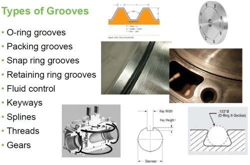
Figure 3 - Types of grooves.
Here, a groove configuration is broadly considered to be anything that is a machined depression that may be a simple radius or that may have a top, sides and a bottom. There are many different groove configurations. Some are very simple, and some are quite complex. Some are easy to get at; some not so easy (Fig. 3). These grooves tend to be square and may or may not have a radius in the bottom corners.
In a perfect world, the deposit distribution is uniform in thickness with good adhesion across all surfaces along both internal and external corners/radii, across all geometries. And of course, we can build-up the deposit infinitely without requiring any machining steps in between plating applications.
In reality, the challenge requires minimizing the build-up of deposit along external corners also known as high current density areas, while increasing the plating throwing power along the internal corners or internal radii where deposit tends to be thinner and not always coherent. The electrolyte takes the path of least resistance. It will travel to high current density areas resulting in a high build-up along external corners, which tends to be rough and dendritic.
Since our solutions generally do not contain additives to enhance leveling and throwing power, we instead optimize plating parameters such as the anode-to-cathode gap, current density, masking and tool fixturing in order to obtain more control of the distribution of the deposit.
Brush plating advancements
Advancements in the technology of brush plating have been many in recent years. Selective areas via anode masking have reduced the build-up along external edges and increased deposit throw along internal radii. This has led to the use of wrap-less plating through use of tighter tolerance tooling and further reduced current densities by selective masking. These advances have made plating in grooves much more reliable.
|
|
Traditional selective / brush plating
Figure 4 shows typical plate distribution obtained with traditional brush/selective plating methods. Sections A and C show a typical ½-inch wide by ¼-inch deep groove. In Section A, the anode is wrapped and seated above the groove. In Section C, a shim piece of anode about 40 mils wide is wrapped with White Tuff Wrap. Because of the wrap thickness, the anode is never properly seated into the groove. As mentioned earlier, brush plating current densities on average are 40 to 60 times higher than those of tank plating current densities. While this is generally an advantage to brush plating in most applications, in the case of groove plating, high current densities don’t always prove to be beneficial.
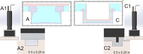
Figure 4 - Traditional selective/brush plating with wrapped anodes placed (a) above the groove and (b) with an anode shim placed internal to the groove.
Using traditional brush plating parameters, we found that thickness distribution tends to be unsatisfactory. The bottom of the groove does not plate to the target thickness, while the external corners have excessive build-up of deposit that is rough, dendritic, and porous. Also, the internal corners, have no coherent plating coverage, and typically the deposit that builds up along the internal corners is only 2 to 5% of the deposit thickness along the crown of the deposit at the bottom center of the groove.
Case 1: Conventional versus wrap-less groove plating
Case 1 presented here involves nickel plating into an OD groove on a 6-inch diameter cylinder. The groove dimensions were ½ × 3/16 in. The target thickness was 5.5 mils, requiring 18 amp-hr of electrolysis. To improve solution flow in the groove (Fig. 5), we took it one step further by taking a nickel tube with holes drilled in it, so solution could flow through it (Fig. 5A & B). The nickel shim also helped increase the plating efficiency by acting as an additional source for nickel ions. We wrapped the anode with Purple TuffWrap® because it is thinner and more flexible than our standard red or white TuffWrap®. We targeted typical brush plating current densities of 3-6 A/in2. Unfortunately, the results were not satisfactory.
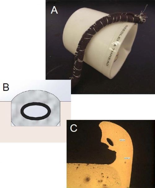
Figure 5 – Conventional nickel brush plating into an OD groove: (A) nickel tube with flow holes; (B) position of the tube in the groove and (C) plate distribution results.
Constant current could not be maintained. The deposit thickness across the OD of the groove was 50% of the target value of 5.5 mils. Excessive build-up which was rough and dendritic along the external corners was evident. Further, numerous power pack overloads and arc outs were experienced during the plating trial due to the wrap catching the rough edges and ultimately ripping. Although, we were able to seat the anode into the groove, we suspect that part of the resistance to plating was caused by lack of solution replenishment into the groove because of the volume taken up by the anode and wrap materials, which inhibited wetting of the electrodes. That coupled with the path of least resistance, the current was mainly drawn to the external corners (Fig. 5C).
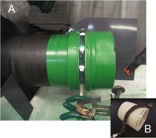
Figure 6 - Case 1: Set-up for wrap-less groove plating.
With a wrap-less technique (Fig. 6), the results were significantly better. The anode was suspended in the groove, using O-rings and Teflon tape to allow the anode to glide without hitting the groove walls. By selectively masking the anodes, we masked off the top and sides of the anode. We also reduced to the current density to 1.0 A/in2. The plating efficiency greatly increased. The deposit thickness was about 8 mils after 8 A-hr. The top edges were much smoother and good coverage was produced along the internal corners.
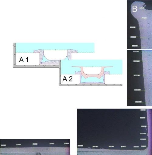
Figure 7 - Case 1: Plate distribution within the groove: (A) computer simulation and (B) actual results.
Figure 7A shows a software simulation of this particular plating trial. Figure 7B shows the cross section of one half of the groove. The maximum thickness along the bottom of the groove was about 8 mils where the crown of the deposit peaks. The deposit tapers off as it moves towards the internal corner to about 1 mil with good coherent coverage. At this point, it is about 10-12% of thickness compared to the crown peak along the bottom of the groove. As the deposit moves up the side wall of the groove, towards the external corner, it increases in thickness to about 15 mils along the corner. The takeaway from this trial was being able to build-up deposit along the bottom of the groove for dimensional restoration while further reducing the external edge effects. This plating trial led to our next thought - what would happen if we could more precisely control the anode-to-cathode gap with precision tight tolerance tooling?
Case 2: Brush plating of selective areas
For this application, only selective areas of the groove required plating. Figure 8A shows in cross-section (also noted as Application 1 in the figure), where the part had been subject to considerable wear in the regions labeled A (red), B (green) and H yellow), representing the sidewalls of the groove. All other areas along the groove, were in good condition and required no additional plating. Application 2 also had similar requirements where only one wall required additional plating for dimensional purposes. The main difference between the two applications was that in Application 1 the part was stationary, while the anode was moving back and forth. In Application 2, the part was rotating on a lathe, while the anode was held on a fixed arm. The groove width was ~1/4 in., while the depth was 3/16 to 1/3 in. The desired thickness was 5 to 13 mils.
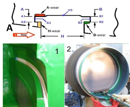
Figure 8 - Case 1: Plate distribution within the groove: (A) computer simulation and (B) actual results.
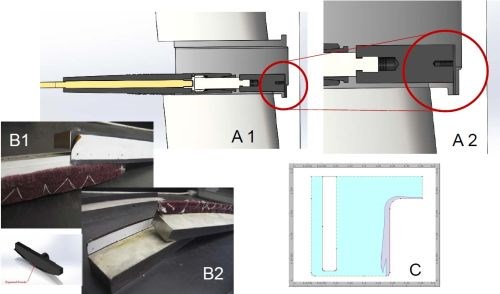
Figure 9 - Case 2: Masking for selective area wrap-less plating of grooves.
In order to distribute the deposit, we chose to selectively mask off the anodes (Fig. 9). In masking the anodes, the concept is along the same lines of logic that tank platers would use to place shields in a tank plating set-up in order to divert the current flow. In these scenarios, we used our Dur-A-Form anodes. The side of the anode facing the substrate area that needed to be plated was only exposed such that only half of the anode was exposed compared to the plating area (along the width), which allowed for the current to be focused toward the internal corners of the groove first, while tapering off toward the top of the groove leading towards the external edges/corners. All other areas of the anode (such as the backside) were masked off to minimize any residual current from going elsewhere. In these applications, we did maintain a brush plating current density of 3 A/in2.
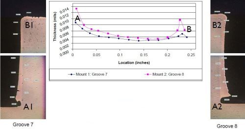
Figure 10 - Case 2: Thickness distribution.
The results are shown in Fig. 10. The photos labeled as Grooves 7 and 8, show a cross-sectioned deposit that is thicker at the bottom of the groove, near the internal corner. On the graph, the point labeled A represents the thickness at the bottom of the groove, where it ranged any from 9 to 13 mils. The deposit then tapered out to ~5 mils as it is moved towards the top of the groove, where it slightly increased in thickness again as represented by point B on the graph. However, it is still not as thick as the bottom of the groove. The takeaway from this application was that we managed to provide additional deposit build-up along the bottom of the groove, while minimizing the external edge effects along the top of the groove while using standard brush plating current densities. The workpiece was plated to size, with no post-machining required.
|
|
Case 3: Wrap-less groove plating an ID groove
This is another groove application that started with traditional brush plating techniques (Fig. 11). The workpiece was a stationary part with off center pockets. The part could not be rotated, and the anode could not be held as is typical. Since this application was for corrosion repair/refurbishment, we applied nickel into two grooves that were around 9/32” wide by 5/32” deep at current density of 0.5 to 1.0 A/in2, using a custom-designed Dur-A-Form® anode (Fig. 11C). It was wrapped with a dense white TuffWrap® material. As with Case 1, there was a significant amount of build-up along the external corners which would cut into the wrap and eventually the anode would arc out.
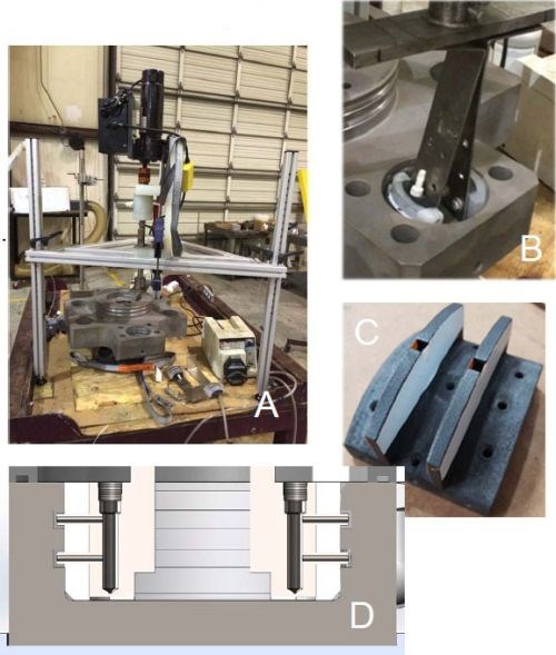
Figure 11 - Case 3: (A) Overall setup; (B) Closeup of anode positioning, (C) Anode design and (D) Schematic cross-section of the plating cell.
With wrap failures again present, we decided to remove the wrap and added plastic guide strips to the anode. These guide strips aided in setting a determined anode-to-cathode gap and helped locate with respect to the plating equipment. We used an ID plater, which was mounted vertically on a tripod stand (Fig. 11A). It consisted of a drive motor with a hollow shaft and pump seals that can flow plating solutions to the rotating anodes. In Fig. 11B, the T-bar and spring arms used to locate the anode can be seen. Centering the shaft, arms and anodes with the pocket becomes very important with the wrap-less tooling because it was designed with tighter tolerances than what we typically use on wrapped anodes. We had less room for misalignment. Although this mechanical set-up helped improve the plating capability, it too had its limitations. The operator had to prep the surface manually and then set-up the ID plater in less than a minute, all the while concerned that the surface did not passivate. Since the initial concept proved to be feasible, we decided to invest in automated equipment where we could better control our tooling placement.
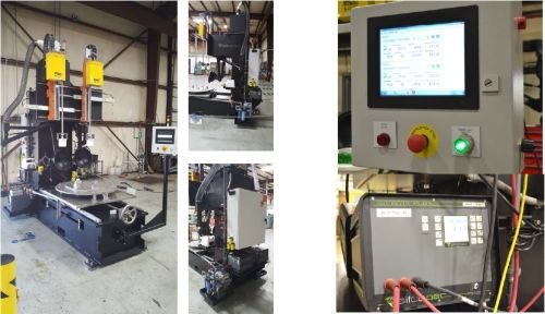
Figure 12- Automated ID plating, rectifier software and data logging.
The resulting machine that was built is shown in Fig. 12. It is a dual spindle “milling machine” where - instead of machining holes - we selectively plate them. Much like the ID plater, plating solution is pumped through a hollow shaft, but a rotary union and an offset drive motor are used. The X axis moves the parts in and out with a hand crank. The Y and Z axes are controlled by servo actuators. A dial indicator is used to center the shaft within a few thousandths of an inch. This completely eliminates the issues encountered in running wrap-less tooling with the ID plater.
|
|
With the HMI machine, we can program plating recipes for repeatability and traceability. The other key variable we changed here, was the introduction of single anode plating. Having better control of the mechanical set-up and the plating process resulted in less variation and optimized plating conditions.
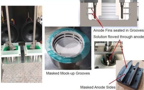
Figure 13 - Automated ID plating operation.
Figure 13 shows the tooling running on the machine. We ran multiple samples of varying current densities and anode-to-cathode gaps. In the cross section of the tooling in the top right corner you can see the flow holes are directed to the center of the grooves. The sides of the anode were masked to help prevent the excess build up in unwanted areas. In the picture in the lower right corner you can see that the bar and spring arms used with the ID plater were replaced with solid titanium construction also with higher tolerances to match the anodes.

Figure 14- Case 3: Effect of anode-to-cathode gap on the plate distribution.
Using tighter tolerance tooling designs which provided for more precisely controlled conditions, we took the opportunity to study plating variables more closely. We looked at the effects of varying current density, anode-to-cathode gaps, and anode RPMs. In Fig. 14A, we found that with larger anode-to-cathode gaps, if the anode was NOT placed in the groove perfectly centered, the deposit crown along the bottom of the groove would have a greater tendency to be skewed in one direction or the other. On the other hand, by using a smaller anode-to-cathode gap, as shown in Fig. 14B, there was no obvious skew of the crown to left or right. The smaller anode-to-cathode gap also provided for a larger plateau crown of deposit along the bottom of the groove, which helped to minimize the taper as it moves towards the internal corners. The deposit in Fig. 14B, was also plated at 3 A/in2. Although, the result at 3 A/in2 is quite good, the higher current density forces a rougher deposit, which ultimately limits the achievable thickness in one application along with limiting the throwing power into the external corners. In both cases, the deposit tapered off along the sidewall, with very little build-up along the external edges - a significant improvement compared to some of the applications discussed previously.
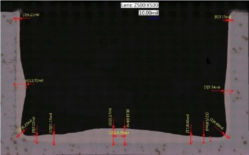
Figure 15 - Case 3: Best case scenario.
In the best case scenario (Fig. 15), we found that the smaller gap of 0.050 inch, coupled with lower current densities of less than 1 A/in2 and a small anode-to-cathode gap, we increased the throw into the corners by 3×. With traditional brush plating methods, we had achieved only 2 to 5% throwing power into the corner, and by removing the wrap, we increased that throwing power to 10 to 12%. Now, we are at about 30 to 35% throwing power into the corner. With these optimized plating variables, we can provide a smooth deposit which allows for higher thickness build-up in one application (as opposed to several), more throw along the internal corners, and virtually no build-up along the external corners. Ultimately, these features reduce the need for multiple applications of the deposit, along with multiple machining passes depending on the customers’ needs.
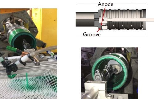
Figure 16 - Another wrap-less application.
Finally, Fig. 16 shows another wrap-less application we did with similar anode design principles, using tight tolerance tooling with a 0.050-inch anode-to-cathode gap and plating at 0.5 A/in2. In this case, we were able to rotate the part on a lathe and while holding the anode stationary as we traditionally do, but masking and locating were challenging. This application had a bore that was a little over 3” in diameter and 7” into the part. The grooves that didn’t need plating were carefully masked off with aluminum tape and peel mask. A plastic plug in the back of the bore served as a masking fixture but also became a locating device to center the anode tooling into the groove. This nickel plating was done at 0.5 A/in2 in multiple applications followed by a machining step after the last application.
Conclusions and future work
There are many aspects to consider when taking on a groove plating application. We need to understand the groove geometry, where the groove is located and how deep and wide it is. What type of deposit are you looking for – for wear or corrosion? Is it for dimensional restoration? Also, more specifically, what is your requirement along the internal corners? Can the deposit taper off within 0.050 inch of the corner? Or does the thickness have to be uniform across the corners and entire groove profile? Can an OEM design be modified to replace sharp corners with chamfers or radii to help optimize brush plating parameters? What are the post finishing requirements?
These answers will help us decide what we can do as far as current density is concerned, what we need to set the anode-to-cathode gaps, and how complex the tooling needs to be. Not every application will have to be done via wrap-less plating on a semi-automated machine. Some applications can be done via brush plating using selective masking techniques and lower current densities. Ultimately, every application needs to be reviewed individually, what we offer here is the necessary fundamental understanding and knowledge and have developed the techniques to successfully plate a variety of groove configurations.
Acknowledgements
The author is grateful to the following people who were instrumental in this study:
- Andy DeLeon – Contract Service Manager Houston
- Derek Kilgore – Mechanical Design Engineer
- Jeff McArthur – Technical Service Rep
- Sarah Medeiros – Corrosion Engineer
- Derek Vanek – Technical Manager
- Teri Zarnesky – Lab Technician
About the author
Danijela Milosevic-Popovich, R&D Manager at SIFCO ASC, joined the company in 2005. She is responsible for the design and execution of lab programs to develop and evaluate current products, new products and plating applications. She also provides the technical support and assistance to the quality, contract service and solutions manufacturing groups. She graduated from the State University of New York at Buffalo with a Bachelor of Science and Master of Engineering in chemical engineering. She then continued to earn her Master of Engineering Management from Ohio University. Prior to joining SIFCO ASC, she worked in the semiconductor (IBM) and rubber industries.
Footnotes:
*Compiled by Dr. James H. Lindsay, Technical Editor - NASF
** Corresponding author:
Danijela Milosevic-Popovich
R&D Manager
SIFCO ASC
5708 E. Schaaf Road
Independence, Ohio 44131
Phone: (216) 750-2237
E-mail: dmilosevic@sifcoasc.com
** Detailed information on these specifications is available at https://www.sifcoasc.com/industry-specifications/ and https://www.sifcoasc.com/commercial-specifications/.
RELATED CONTENT
-
Copper Plating on Aluminum and Aluminum Alloys
How can I plate copper on aluminum?
-
A Chromium Plating Overview
An overview of decorative and hard chromium electroplating processes.
-
Plating Q&A: Can you color stainless steel?
Our expert, Art Kushner, says yes, you can color stainless steel, but it is not a process that is typically performed in a plating shop. Read more about his answer.


