NASF/AESF Foundation Research Project #122: Electrochemical Approaches to Treatment of PFAS in Plating Wastewater - 9th Quarterly Report
The NASF-AESF Foundation Research Board selected a project addressing the problem of PFAS and related chemicals in plating wastewater streams. This report covers the ninth quarter of work (January-March 2023). In this report, we describe our work on evaluating the performance of PFAS degradation by electrooxidation using surface fluorinated Ti4O7 anodes in batch mode.
#pollutioncontrol #nasf
by
Qingguo (Jack) Huang* and Yuqing Ji
College of Agricultural and Environmental Science
University of Georgia
Griffin, GA, USA
Editor’s Note: The NASF-AESF Foundation Research Board selected a project addressing the problem of PFAS and related chemicals in plating wastewater streams. This report covers the ninth quarter of work (January-March 2023). A printable PDF version of this report is available by clicking HERE.
Featured Content
1. Introduction
This project started in January 2021 with the goal of developing applicable electrochemical approaches to remove per- and polyfluoroalkyl substances (PFASs) present in plating wastewaters, including electrooxidation (EO) and electrocoagulation (EC). This project includes three research tasks that are designed to investigate EC, EO and EC-EO treatment train, respectively, designed to probe three hypotheses specified follows:
1) EC generates amorphous metal hydroxide flocs that can effectively adsorb PFASs in plating wastewater, which, through an appropriate treatment, can release PFASs into a concentrated solution.
2) EO enabled by a Magnéli phase Ti4O7 anode can be used to effectively destruct PFASs in plating wastewater.
3) The electrochemical treatment train comprised of EC and EO by Ti4O7 anode can remove and degrade PFASs in plating wastewater more efficiently than either process operated individually.
Our previous report described our work to prepare and characterize surface fluorinated Ti4O7 anodes. The XPS test results have confirmed the anodes as being successfully surface fluorinated using an electrodeposition procedure in a reactive electrochemical membrane (REM) reactor. In this quarterly report, we describe our work on evaluating the performance of PFAS degradation by electrooxidation using surface fluorinated Ti4O7 anodes in batch mode.
2. Experimental
Batch electrooxidation experiments were conducted using an acrylic electrolytic cell (6.50 cm × 5.50 cm × 5.70 cm) containing 50 mL reaction solution. A pristine or a surface-fluorinated Ti4O7 plate was placed in the middle as the anode, and two 316 stainless steel plates of the same size and shape as the anode were placed on either side in parallel at a 2.50-cm gap as the cathodes, with a constant current density applied using a DC power source (Tacklife Inc, China). The reaction solution contained a mixture of PFOS, PFOA and 6:2 FTS (2.0 μM each), 100 mM Na2SO4 and 10 mM NaCl as supporting electrolytes. Duplicate 500 μL samples were taken at each prescribed interval for chemical analysis. A 400-μL aliquot was mixed with 400 μL methanol containing 80 ppb M8PFOS, M8PFOA and M2-6:2 FTS, filtered through a 0.22-μm polypropylene filter and then stored at 4℃ for subsequent analysis of PFAS. All experiments were performed at room temperature at least twice to ensure consistent results.
3. Results and discussion
The batch experiments of EO treatment were performed at five different current densities, including 2.5, 5.0, 7.5, 10 and 15 mA/cm2, for which the anodic potentials measured for each anode are summarized in Table 1.
Table 1 - Current density and corresponding anodic potential on pristine and fluorinated Ti4O7 anodes.

Table 1 - Current density and corresponding anodic potential on pristine and fluorinated Ti4O7 anodes.
The degradation of PFOA, PFOS and 6:2 FTS in all systems appeared to follow a pseudo-first order kinetic model. The observed reaction rate constant kobs,PFAS of PFAS degradation was calculated by data fitting to the equation:
(1)
where Co,PFAS is the substrate concentration at time zero (mol/L); Ct,PFAS is the substrate concentration (mol/L) at time t (sec), PFAS in the subscript can be PFOA, PFOS or 6:2 FTS.
It should be noted that different anodes had different effective electroactive surface area-to-solution volume ratios. Therefore, the PFAS degradation rate constant normalized to effective electroactive surface area (kSA,PFAS ) was calculated to facilitate the comparison of reactivity among different pristine and surface-fluorinated Ti4O7 anodes. The surface area normalized reaction rate constant (kSA,PFAS ) was calculated by the following equation (Valentine Richard and Wang, 1998)2:
kSA,PFAS = kobs,PFAS × (2)
where S is the effective electroactive surface area (EESA) of the anode (m2), V is the volume of the reaction solution (m3) corresponding to the effective electroactive surface area; PFAS in the subscript can be PFOA, PFOS or 6:2 FTS.
The change of the concentrations of PFOA, PFOS and 6:2 FTS during EO with the pristine and fluorinated Ti4O7 anodes at 5 mA/cm2 are presented in Figure 1. Over 99% removal of all three PFASs was observed within 8 hours of EO treatment on the pristine and all-fluorinated anodes.

Figure 1 - The degradation of (A) PFOA, (B) PFOS and (C) 6:2 FTS during EO with pristine and fluorinated Ti4O7 anodes at 5 mA/cm2 in a mixed solution containing each of the three PFAS at 2.0 μM initial concentration. Supporting electrolytes: 100 mM Na2SO4 + 10 mM NaCl. The error bar represents standard deviations of replicates.
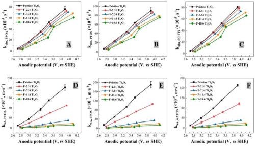
Figure 2 - Observed reaction rate constant kobs, PFAS in relation to the anodic potential for (A) PFOA, (B) PFOS and (C) 6:2 FTS degradation using pristine and fluorinated Ti4O7 anodes; surface area normalized kSA,PFAS in relation to the anodic potential for (D) PFOA, (E) PFOS and (F) 6:2 FTS degradation using pristine and fluorinated Ti4O7 anodes. Initial PFAS concentration: 2 μM, supporting electrolyte: 100 mM Na2SO4 + 10 mM NaCl. The error bar represents standard deviations of replicates.
The observed reaction rate constant and the surface area normalized rate constant for the degradation of PFOA, PFOS and 6:2 FTS on pristine and fluorinated Ti4O7 anodes are displayed in Figure 2. It is evident that the observed reaction rate constants for all three PFASs were the highest for the system with the pristine Ti4O7 anode and decreased with increasing fluorination percentage on the anode surface. Taking the reaction rates at 10 mA/cm2 as an example, kobs,PFOA decreased by 4.63%, 7.20%, 10.3% and 20.2% on F-2.31, F-7.34, F-11.4 and F-18.6 Ti4O7 anodes, respectively, in comparison to the pristine Ti4O7 anode (Figure 2A), while the anodic potential increased slightly from 3.50 V for the pristine Ti4O7 anode to 3.61 V for the F-18.6 anode (Table 2). Similar trends were observed for kobs,PFOS and kobs,6:2 FTS (Figs. 2B and 2C) as well. When the rate constants were normalized to the EESA, larger differences were seen between the pristine and fluorinated anodes. For example, the kSA,PFOA decreased by 45.0%, 82.5%, 89.2% and 92.4% on F-2.31, F-7.34, F-11.4 and F-18.6 Ti4O7 anodes, respectively, compared to the pristine Ti4O7 anode (Fig. 2D), and the trends of kSA,PFOS and kSA,6:2 FTS were similar (Figs. 2E and 2F). This suggests that the intrinsic reactivity of the Ti4O7 anode towards PFAS was reduced upon surface fluorination, while the reduction of performance was compensated for by the increased EESA of the anodes resulting from fluorination (Table 3). Control experiments were performed in the same system with no current applied on pristine and F-18.6 Ti4O7 anodes. The result indicates that adsorption of PFOA, PFOS and 6:2 FTS on both the pristine and fluorinated Ti4O7 anodes are minimal.
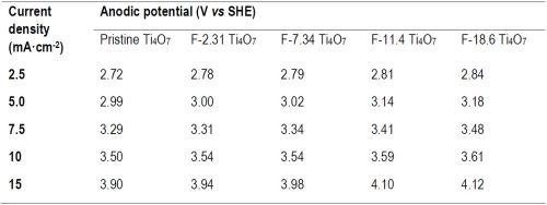
Table 2 - Current density and corresponding anodic potential on pristine and fluorinated Ti4O7 anodes.

Table 3 - Total, outer and inner charge values and EESA of pristine and fluorinated Ti4O7 anodes.
4. References
1. Richard L. Valentine and H.C.A. Wang, “Iron Oxide Surface Catalyzed Oxidation of Quinoline by Hydrogen Peroxide. Journal of Environmental Engineering, 124, 31-38 (1998)
5. Past project reports
1. Introduction to Project R-122: Summary: NASF Report in Products Finishing; NASF Surface Technology White Papers, 85 (6), 13 (March 2021); Full paper: http://short.pfonline.com/NASF21Mar1.
2. Quarter 1 (January-March 2021): Summary: NASF Report in Products Finishing; NASF Surface Technology White Papers, 85 (12), 13 (September 2021); Full paper: http://short.pfonline.com/NASF21Sep1.
3. Quarter 2 (April-June 2021): Summary: NASF Report in Products Finishing; NASF Surface Technology White Papers, 86 (3), 18 (December 2021); Full paper: http://short.pfonline.com/NASF21Dec2.
4. Quarter 3 (July-September 2021): Summary: NASF Report in Products Finishing; NASF Surface Technology White Papers, 86 (6), 16 (March 2022); Full paper: http://short.pfonline.com/NASF22Mar2.
5. Quarter 4 (October-December 2021): Summary: NASF Report in Products Finishing; NASF Surface Technology White Papers, 86 (9), 21 (June 2022); Full paper: http://short.pfonline.com/NASF22Jun2.
6. Quarter 5 (January-March 2022): Summary: NASF Report in Products Finishing; NASF Surface Technology White Papers, 86 (12), 22 (September 2022); Full paper: http://short.pfonline.com/NASF22Sep2.
7. Quarter 6 (April-June 2022): Summary: NASF Report in Products Finishing; NASF Surface Technology White Papers, 87 (3), 17 (December 2022); Full paper: http://short.pfonline.com/NASF22Dec1.
8. Quarter 7 (July-September 2022): Summary: NASF Report in Products Finishing; NASF Surface Technology White Papers, 87 (6), 19 (March 2023); Full paper: http://short.pfonline.com/NASF23Mar2.
9. Quarter 8 (October-December 2022): Summary: NASF Report in Products Finishing; NASF Surface Technology White Papers, 87 (9), 19 (June 2023); Full paper: http://short.pfonline.com/NASF23Jun1.
6. About the principal investigator

Qingguo (Jack) Huang is Professor in the Department of Crop and Soil Sciences, University of Georgia, Griffin Campus. He holds a B.S. in Environmental Science (1990) and a Ph.D. in Chemistry (1995) from Nanjing University, China as well as a Ph.D. in Environmenal Engineering from the University of Michigan, Ann Arbor, Michigan. Dr. Huang’s research interest focuses on catalysis involved in the environmental transformation of organic pollutants, and development of catalysis-based technology for pollution control and environmental remediation and management. His laboratory has been actively involved in several cutting-edge research topics:
- Enzyme-based technology for water/wastewater treatment and soil remediation
- Electrochemical and reactive electrochemical membrane processes in wastewater treatment
- Catalysis in biofuel production and agro-ecosystem management
- Environmental fate and destructive treatment methods of PFASs
- Environmental application and implication of nanomaterials
He has published over 170 peer-reviewed journal articles, five book chapters and had six patents awarded. He has taught three courses at the University Georgia: Introduction to Water Quality, Environmental Measurement and Advanced Instrumental Analysis in Environmental Studies.
* Principal Investigator (PI) Contact Information:
Qingguo Huang, Ph.D,
Professor, Department of Crop and Soil Sciences,
University of Georgia,
1109 Experiment St.,
Griffin, GA 30215, USA.
Phone: (770) 229-3302
Fax: (770) 412-4734
E-mail: qhuang@uga.edu
RELATED CONTENT
-
Treating Plating Wastewater
Wastewater from plating facilities contains contaminants such as heavy metals, oil and grease and suspended solids at levels that might be considered environmentally hazardous . . .
-
Plating Q&A: Can you color stainless steel?
Our expert, Art Kushner, says yes, you can color stainless steel, but it is not a process that is typically performed in a plating shop. Read more about his answer.
-
Filter Press Troubleshooting and Optimization
Zachary Beckman of Haviland Enterprises Inc. discusses proper filter press maintenance for optimization of wastewater treatment systems.


