
Robust Colored Coating on Light Metal Alloys
A paper* based on a Presentation given at NASF SUR/FIN 2022 (Rosemont, Illinois) by Chris Goode** Cirrus Materials Science Ltd.
#nasf
Share
A paper* based on a Presentation given at NASF SUR/FIN 2022 (Rosemont, Illinois)
by Chris Goode**
Cirrus Materials Science Ltd.
Auckland, New Zealand
Editor’s Note: The following is a paper based on a presentation given at NASF SUR/FIN 2022, in Rosemont, Illinois on June 8, 2022, in Session 7, Decorative Automotive Considerations. A pdf of this paper can be accessed and printed HERE.
Featured Content


ABSTRACT
This paper offers an introduction to a new matte or gloss finish for aluminum that seeks to alleviate many of the carbon and VOC issues associated with paint. Cirrus Paint‐Free Colour™ is an innovative surface finishing technology that generates wide range of colors on light metal alloys or 3D‐printed components from a sustainable cost and energy effective process. The colored coatings are thin but provide effective corrosion and scratch resistance.
Introduction
Light metal alloys, such as aluminum, have the high strength‐to‐weight performance that is important
to the architectural, automotive and aerospace sectors. These applications frequently require a colored protective finish. Conventional paint and similar organic coating processes are energy intensive, often require hazardous chemicals, emit volatile organic compounds (VOC) and have the potential to cause environmental contamination requiring costly containment measures. Industry requires an environmentally sustainable process to produce protective surface finishes having vibrant colors.
Cirrus is a New Zealand company that focuses on developing innovative surface finishing technologies. Our customer base is technology end users with surface finishing problems for which Cirrus technologies add value. Cirrus Paint‐Free Colour™ is an extension of Cirrus Hybrid™ technology which develops nanostructured aluminum surfaces to support adherent functional coating deposition. Unlike the conventional approaches, which use paints or dyes to create color, Cirrus Paint‐Free Colour™ develops visible light resonant nanostructures using a low temperature and low power process that eliminates virtually 100% of VOCs. Building on the hybrid technology, the tightly interlocked nanostructured alumina and metal deposits are much more adherent than conventional paint. The nanostructures are tunable to produce a wide range of vibrant colors from a thin coating, typically between 3 and 15 microns which provides good corrosion protection and scratch resistance. Cirrus Paint‐Free Colour™ for aluminum is 75% thinner, lighter and five times more energy efficient than traditional painted surfaces and offers a disruptive new sustainable coating system for light metal alloys and 3D‐printed components. This paper provides an update on paint-free color technology development.
Background
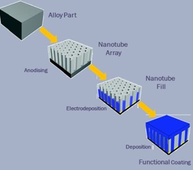
Figure 1 – Schematic diagram of anodizing/electroplating hybrid development.
In 2016, Cirrus developed an efficient coating process that combined anodizing and electrolytic or autocatalytic plating to provide conductive protective surfaces on aluminum substrates (Fig. 1). This process significantly lowered both the energy and time required to deposit protective coatings on a wide range of aluminum alloys. The technology while protecting the substrates simultaneously developed useful surface functionalities including high hardness, enhanced wear resistance, high corrosion resistance and excellent conductivity. Slight modifications to the deposition process allowed the creation of surfaces with low drag resistance, and hydrophobic or hydrophilic properties, etc. The process supported production of anodizing / electroplating hybrids on aluminum and titanium alloys.
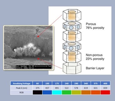
Figure 2 – Basis of Cirrus Paint Free Colour™ development.
The creation of Cirrus Paint Free Colour™ was a direct outcome of our development of Cirrus Hybrid™ technology, as we discovered that while depositing nickel, or another metal, into the hybrid alumina pores, the surfaces first turned black and grey before becoming silver during electrodeposition. A diagrammatic representation of the paint free color surface is shown in Fig. 2, right.
One of the attributes of the Hybrid/Paint Free Colour™ anodizing bath and process is the development of periodically spaced side pores connecting the main anodizing pores, the SEM insert in Fig. 2 shows the anodizing / plating structure of a black PFC surface. Here a 60 V anodizing process developed the cross section imaged by SEM.
A plethora of measurements from many SEM images of both the main pore and side pore geometries suggest that there is a relationship between the anodizing voltage, the bath temperature, the barrier layer thickness and the side pore spacing. While the side pore spacing is related to the anodizing voltage, and the bath temperature, acidity influences are dominate side pore diameter, since the anodizing process seeds the side pores, which then grow from alumina dissolution.
Initial colored surfaces adopted an incomplete metal fill, as we believed that there the air/alumina matrix was required. Here we modelled the color generation process as multiple coating layers having varied refractive indices. These layers comprised: the main pore surrounded by alumina, the main pore with side pores and alumina, the same structures with a metal fill, the barrier layer, and the substrate. Simulations using this model suggested that all visible colors could be created by varying the anodizing voltage between about 60 V and about 350 V (Fig. 2 lower).
We were successful in translating this theory to practice and produced colors from black through yellow towards green. The colors however, except for the violets, were both muted and subject to thin film interference distortion. In addition, we had significant difficulties in controlling the process sufficiently to create colors with a low delta E for consistent color matching.
Mechanism
In our most recent work, we have discovered that paint free color structures still produce color when nickel, or another metal, entirely filled the pores. This outcome required a significant rethink of the color generation model.
Working with the University of Auckland Photon Factory, we created a new model, dependent on just two photonic crystal structures shown in Fig. 3.
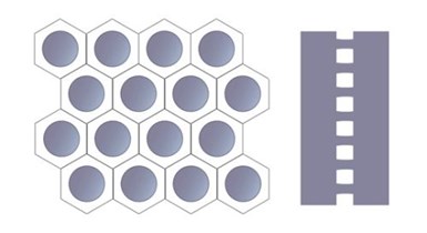
Figure 3 – Photonic crystal structures.
The leftmost diagram shows a plan model of the alumina/metal main pore structure. Previous literature reported the photonic behavior of this structure; however, these structures are less important to color generation. The second elevation view diagram, to the right, depicts the transparent alumina pore walls and the metal filled side pores, here our work with the Photon Factory demonstrated that reflective resonance was a function of side pore geometry. Photonic resonance using the metal filled side pores offers the potential for saturated colors with no interference effects, assuming that the periodic side pore geometry is accurately controlled.
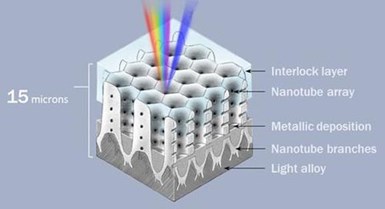
Figure 4 – Mechanism of nanostructure tuned to desired wavelength of light.
The nanostructure created by the Cirrus Paint Free Colour™ technology can be tuned to the desired wavelength of light, generating an accurate and consistent color match (Fig. 4).
Side pore geometry
As discussed above, the diameter and spacing of the side pores is crucial to both developing color and creating a full color spectrum. Saturated color generation requires firstly, a consistent anodizing pore structure and secondly a sufficiently thin barrier layer to allow complete metal pore fill and finally side pores of uniform geometry.

Figure 5 – Effect of anodizing voltage and bath temperature on side pore geometry.
We have exhaustively researched anodizing bath chemistries that allow the production of repeatable PFC nanostructures. The graph in Fig. 5 shows a small subset of the relationships between the side pore geometries, the anodizing voltage and the bath temperature. The yellow line shows an approximately linear relationship between the side pore spacing and the anodizing voltage.
The orange line demonstrates the more nuanced relationship between the side pore diameter and the anodizing voltage. As previously mentioned, apart from anodizing voltage, the bath temperature and bath acid content both affect the side pore geometry. Here, it is important to highlight the adoption of identical anodizing parameters, except temperature, when we produced the surfaces from which we made the measurements for the two dots points on the 140 V line. A 9-degree temperature difference between the baths produced the reported pore geometries. The corresponding yellow dots show a much less pronounced temperature effect on side pore spacing. Thus, the color control parameters are primarily the anodizing voltage, the bath acidity and the bath temperature.
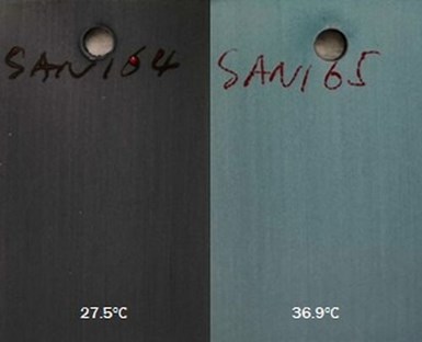
Figure 6 - Effect of side pore diameter on the coating color.
Fig. 6 illustrates effect of side pore diameter on the coating color. The two images are of the samples produced using the anodizing process parameters described in Fig. 5. Both samples followed an identical metal fill process. The alumina structure, for the color surface on the left, with side pores of about eighty nanometers in diameter and inter side pore distances of about 155 nanometers, have a reflective resonance in the ultraviolet range and thus a black appearance. The alumina structures from which the color surface on the right was produced, having an average pore diameter of 135 nanometers and interpore spacing of 185 nanometers, is resonant in the blue/green region. The lack of spectral purity on the blue green sample is a function of the much broader distribution of side pore diameters from the substrate to the surface, due to the varying bath acid exposure times, which creates a much wider reflective resonance. Bath additives have been shown to significantly reduce the side pore diameter variation.
Surface texture – Gloss to Matte
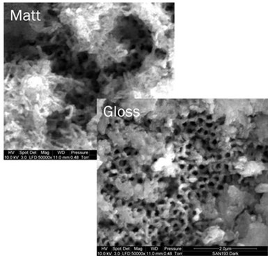
Figure 7 – SEM images of gloss and matte surfaces.
Figure 7 illustrates the production of gloss and matte surfaces. The specular reflection of the surface depends on both the metal and alumina structures produced during both anodizing and plating. The top image shows a SEM of a matte surface while the bottom image shows a gloss surface. EDS analyses identified the matte surface structures as a combination of very porous metal-oxide and etched alumina. These micro/nano structures absorb light that would otherwise reflect from the alumina/metal surface, producing a surface having a total reflection of well under 1%. Sample processing post metallization may either reinforce or eliminate these structures.
Process control – Colors, textures and shapes
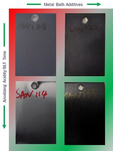
Figure 8 - Effects of metal bath additives and anodizing bath acidity on color outcomes.
Figure 8 shows the effects of metal bath additives and anodizing bath acidity on color outcomes. Here, we show a sequence of black samples produced under a variety of anodizing and plating conditions. As previously mentioned, controlling the anodizing bath acidity and conductivity is critical to developing the required anodizing structures. The optimum chemistry for maintaining the necessary balance between film production and dissolution combined a low acid content using water and ethylene glycol as the solvents. Such baths produced the best, most consistent outcomes.
We have also discovered that managing the metal fill process is essential to producing vivid colors, the nickel must grow uniformly from the base of the pores to completely fill the main pores and the side pores. The conductivity of the barrier layer controls the rate of metal growth in the pores; thus, as the anodizing voltages increase, a barrier layer thinning step is essential to reliable color production. We have found that constant current barrier layer thinning offers the best results.
Metal bath additives together with a tightly managed plating current profile produces the most consistent, uniform metal fill. These additives manage the nucleation process by modifying the metal reduction potential ensuring even nucleation at the base of the pores, and slow uniform growth up through the pore structure.
Many metals can be used to fill the pores. Cirrus primarily uses nickel; however, we have also produced successful colored samples with silver, tin and cobalt, among other metals. The primary attribute that is responsible for the photonic effect is reflective index difference between the metal and alumina, however the absorption of the metal is also important.
As discussed, a combination of anodizing and metal-plating chemistries tightly control the production of colored surfaces. The latest developments in Cirrus’ paint free color technology have transformed the process to one that can produce narrow spectrum vivid colors on a variety of substrate shapes, shown in Figure 9.

Figure 9 – Samples of the variety of possible coating shapes and textures.
The image on the left shows a matte black surface on a flat sample. This sample was produced in an ethylene glycol bath with low phosphoric acid concentration using an anodizing voltage of about 60 V. The matte black sample has a very low delta E and total reflectance <1%, specular reflectance is almost eliminated making the surface suitable for optical applications.
The center image is a glossy black color produced on a 3-dimensional curved sample where the anodizing specification is identical to that of the first image. However, the nickel deposition bath formulation was slightly modified to eliminate the surface features responsible for the matte surface. The nickel deposition parameters remain identical to those for the flat sample. Once again, this coating has a low delta E and a reflectance < 1%, however the specular reflectance is quite high.
The image on the right is a gloss black surface, demonstrating the ability of the process to coat complex shapes, in this case a connector rail. We have also produced black surfaces on shapes such as heatsinks for which the thermal performance of the coating makes it potentially an ideal alternative to black anodizing.
The images in Fig. 10 show examples of glossy and matte blue samples created with a higher anodizing voltage, about 90 V. Here the bath compositions and plating current profiles are identical to those adopted for the previous black samples, albeit it with a modified barrier layer thinning current profile. Varying the anodizing voltage creates a range of violets and blues.

Figure 10 – Samples of glossy and matte blue samples.
In each case the anodizing process time was 10 minutes, which produces between about 2-4 microns of anodized surface. Previously, higher anodizing and plating times, produced colored surfaces with anodizing thickness of up to about 10 microns.
The apparent lack of uniformity in the two glossy blue samples, on the left, is a function of specular reflectance and the imaging process. However, the measured delta E for these surfaces is less than 1. The PFC process can also produce colors in the yellow and green spectrum, as previously noted. However, these colors are currently muted due to a wider than desired spectral response caused by variations in the side pore diameters.
Properties and performance
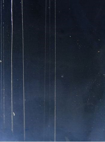
Figure 11 – Scratch resistance.
In Cirrus Paint Free Colour™, the coating nanostructure, rather than dyes or other coloration mechanisms, produces the color which means that, unlike traditional paints or surface coloring processes, shallow scratches and nicks do not affect the perceived color. Figure 11 shows an image of a 2-micron blue/black sample both lightly and heavily scored. The light scoring on the right has little or no effect on the original color while the deeper scoring on the left penetrates the coating and the substrate becomes visible.
The metal/alumina structure of the coating is harder and inherently more scratch resistant than painted surfaces or dyed anodized surfaces. With the addition of a Cirrus Dopant™ to the plating bath the hardness of the surface can exceed 900 HV, providing a much higher performance. Finally, a seal layer possibly required to produce the requisite corrosion resistance provides an additional layer of protection to the surface.
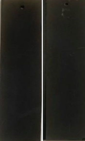
Figure 12 - Ultraviolet resistance.
Another required attribute of colored surfaces is UV resistance. In Fig. 12, the structural color production is shown to provide outstanding performance. The images shown here depict (left) unsealed black samples as coated and (right) after one thousand hours of UV exposure. As expected, the coating shows no color deterioration. Interestingly, and not shown, the samples protected with Cirrus PolyShield™ also exhibited no hazing after an equivalent period of UV exposure. The high radiation resistance of the paint free color surfaces offers potential for developing stable calibration fiducials for space-based instrumentation.
An important characteristic of a paint system is its ability to protect the underlying surface from corrosion. In hybrid surfaces on aluminum the metal fill creates potential corrosion cells with moisture ingress. There are many approaches to reduce the corrosion risk, one is the selection of the metal species, for example. Zinc protects aluminum well and can be used to create PFC surfaces, albeit with greater difficulty in controlling the metal fill function. Alternatively, doping elements in the metal can reduce the corrosion couple and provide protection. Here, we have experimented with cerium compounds. Finally, depositing a protective layer over the PFC surface provides corrosion protection.
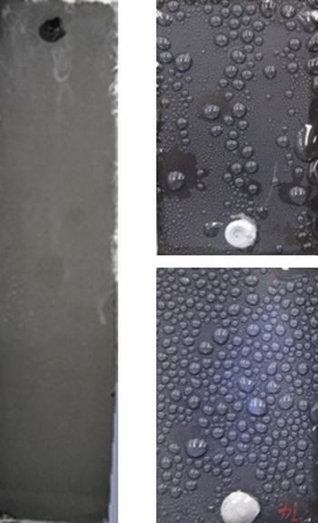
Figure 13 – Corrosion resistance.
Figure 13 shows a black Paint Free Color™ sample coated with Cirrus Polyshield™, a 40-micron surface-initiated polymer coating which survived more than 1500 hours of neutral salt spray as shown in the left most image. The image to the right shows two color samples sealed with a commercial clear ceramic surface after two hundred hours of testing. The commercial seal creates a slight change in sample coloration. This is due to air entrapment created by the spray application method which produced the slightly hazy finish on these small samples.
Applicability
The substrate used on all paint free color images shown so far was 6061-T6 aluminum, although we originally developed the technology on five series alloys. Last year Cirrus commenced a program to understand the extent to which the technology was applicable on a full series of aluminum alloys. We deposited black paint free color on exemplar 2000, 3000, 4000, 5000, 6000 and 7000 series alloys.

Figure 14 – Applicability to other aluminum alloy substrates.
Figure 14 shows a subset of the early samples produced on all these alloys using the original PFC process. The slight specular color variation in the 7075 series samples resulted from not completely filling the pores with nickel. In each case, the alloys required minor modification to the anodizing chemistry to develop the appropriate nano structures. Other than that, the PFC process was largely substrate invariant.
Summary
This paper has discussed many technical aspects of the Cirrus Paint Free Colour™ system process and performance. Cirrus, however, is a technology innovator and developer, not a coating solutions provider. We hope the derivatives of the PFC technology can deliver to industry a new opportunity to produce high performance color on light metal substrates. The main benefits of the technology are lower material consumption through thinner coatings, faster lower energy processes through the elimination of drying steps, and lower or no VOC emission.
We are currently evaluating the opportunities for black PFC surfaces, this being the color coating with the highest technology readiness level. One such application is a replacement for black anodizing on heatsinks. We have also been testing matte black surfaces as optical coatings. Measurements of the surfaces show a total reflectance of much less than 1% and a specular reflectance of about 1%. PFC may also be applicable in situations where radiation may cause color deterioration, as demonstrated by the UV performance of the surface, thus fiducials for space-based spectrometer calibration could be an early application for this technology. However, in the long-term replacing paints with their high energy requirements and high VOC emissions remains the primary target.
About the author

Chris Goode is a founder and Chief Technical Officer at Cirrus Materials Science Ltd., in Auckland, New Zealand. Chris holds an honors degree in engineering from the University of Western Australia. He holds over 30 patents and has extensive experience in multiple fields of engineering including telecommunications robotics and chemical engineering.
RELATED CONTENT
-
Cyanide-Free Electroplating of Cu-Sn Alloys
This paper is a peer-reviewed and edited version of a presentation delivered at NASF SUR/FIN 2012 in Las Vegas, Nev., on June 13, 2012.
-
Plastics and Plating on Plastics [1944]
This republished 1944 AES convention paper presents an historic perspective of the early days of plastics in surface finishing - using them and plating on them, in the waning years of World War II. The discussion reviews the uses of plastics in plating equipment and processing at that time, as well as the coating of the plastics themselves, with accompanying application photos. You will note that today’s conventional plating-on-plastics processes lay far in the future. Surprisingly, CVD processes are discussed.
-
Development of a Sustainability Metrics System and a Technical Solution Method for Sustainable Metal Finishing: AESF Research Project #R-121, 6th Quarterly Report
The NASF Research Board has funded a research grant at Wayne State University on sustainability in the surface finishing industry, under the direction of Professor Yinlun Huang. The objective of the work is to create a surface-finishing-specific sustainability metrics system to measure economic, environmental and social sustainability. In this report, a benchmarking study of five plants was undertaken to illustrate how the sustainability assessment works.


