
The Basics of Automotive Surface Engineering by Isotropic Superfinishing
This paper discusses using a non-abrasive, high density media in conjunction with an isotropic superfinishing (ISF) chemistry. This improved surface significantly reduces friction and provides several engineering advantages. The paper also reviews the technique used to generate ISF and some of the improvements that can be imparted to metal-to-metal contact surfaces.
#basics #nasf #surfin
Share
by
William P. Nebiolo*
REM Chemicals, Inc.
Southington, CT, USA
Editor’s Note: This paper was presented on November 4, 2021, at SUR/FIN 2021 in Detroit, Michigan, in Session 9: Advances in Automotive Finishing. A printable pdf of this paper can be accessed and printed HERE, and the accompanying Powerpoint presentation can be accessed HERE.
Featured Content


ABSTRACT
Certain machined, engineered components are functionally operative because they interact with their complementary partners to transmit energy/motion. Examples are bearings or gears. As a function of their operational efficiency, the metal-to-metal contact location becomes an area of engineering concern since this contact point is a probable area of parasitic frictional resistance. As such, the finish of the metal-to-metal contact areas becomes a critical variable in the efficiency equation related to energy or motion transfer. Typically, machined parts that have been polished to improve their final surface finish will have a unidirectional surface pattern that corresponds to the direction of polishing. Although the polished surface is improved, the presence of polishing line asperities minimizes metal-to-metal contact because component contact is asperity peak-to-asperity peak. Vibratory bowls are commonly used for generic deburring. By utilizing non-abrasive, high-density media in conjunction with an isotropic superfinishing (ISF) chemistry, surfaces can be superfinished to an isotropic or random finish. This improved surface increases energy/motion transfer efficiency in the metal-to-metal contact area by reducing friction and providing several engineering advantages. This paper will review the technique used to generate the isotropic surface finish and will also review some of the engineering advantages that can be imparted to metal-to-metal contact surfaces.
Introduction
Certain machined, engineered components are functionally operative because they interact with their complementary partners to transmit energy/motion. Examples of engineered items that transmit energy/motion are bearings or gears. These engineered items transmit energy/motion by rolling, sliding, rotating or engaging their complementary partners.
As a function of their operational efficiency, the metal-to-metal contact location of the complementary partners becomes an area of great engineering concern, since this contact point is a probable area of parasitic frictional resistance. As such, the finish of the metal-to-metal contact areas becomes a critical variable in the efficiency equation related to energy or motion transfer.
Typically, machined parts that have been subsequently polished to improve their final surface finish will have under magnification a unidirectional surface pattern that corresponds to the direction of polishing. Although the resulting polished surface is improved versus its original machined condition, the presence of the polishing line asperities minimizes metal-to-metal contact between complementary components because component contact is actually asperity peak-to-asperity peak.
Vibratory bowls are commonly used in metal finishing for generic deburring. By utilizing non-abrasive, high-density media in conjunction with an isotropic superfinishing (ISF) chemistry the surfaces of the complementary components can be superfinished to an isotropic or random finish. This improved surface increases energy/motion transfer efficiency in the metal-to-metal contact area by reducing friction and providing an additional number of engineering advantages.
This paper will review the technique used to generate the improved isotropic surface finish and will additionally review some of the engineering advantages that can be imparted to metal-to-metal contact surfaces.
Traditional finishing operations
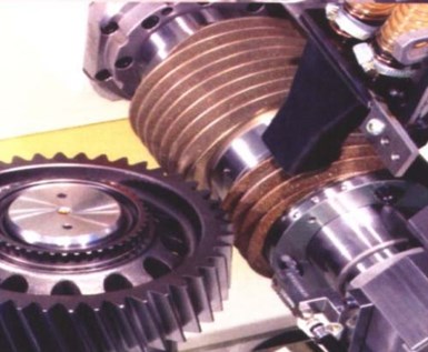
Figure 1 - The teeth of a helical gear being ground.
Grinding and/or lapping are the traditional, final, metal finishing operations done to engineered metal-to-metal contact surfaces such as roller bearings or automotive transmission or spiral bevel gears1,2 (Fig. 1).
An optical scan examination of components prepared using a final grinding operation reveals a surface with a final unidirectional pattern that corresponds to the direction of grinding operation1,2,3 (Fig. 2).

Figure 2 - A magnified view of a ground surface.1-3 Note the unidirectional parallel rows of asperities corresponding to the final direction of the grinding operation.
Grinding with successively finer grinding wheels is expensive, repetitious and ineffective because it simply results in a surface that has more, closer-spaced rows of shorter height asperities.
The ISF™ surface
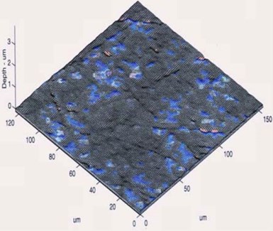
Figure 3 - A magnified view of an isotropically prepared surface.1-3 Note, the parallel rows of asperity peaks as seen in Fig. 2 are non-existent and the final surface is smoother and random with no directional pattern.
It has been reported that metal-to-metal contact areas, if refined by isotropic superfinishing (ISF), will have a resultant isotropic surface.1-7 An ISF surface does not have a unidirectional pattern but is random and non-directional3,8 (Fig. 3).
Metal-to-metal contact: Traditional surfaces vs. ISF™ surfaces
When placed into operation for the first time, components that have been prepared using a traditional grinding operation have a minimal area of initial metal-to-metal contact because this initial contact is actually asperity peak-to-asperity peak.9,10 Such complementary components concentrate contact stress into a few isolated locations of asperity to asperity contact. 9,10
Parts that have been isotropically prepared have an improved metal-to-metal contact pattern because the asperities on the complementary components have been planarized. The final surface is smoother and compressive contact stress is now diffused over a wider area due to the improved contact pattern.2
Generating the ISF™ finish
Using techniques described earlier,1,2,4,6,7,11,12 ISF is produced using a chemically accelerated vibratory finishing process. The parts to be isotropically finished are placed into a vibratory unit containing high-density, non-abrasive media12 (Figs. 4 and 5).
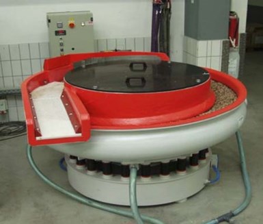
Figure 4 - A traditional vibe bowl with parts/media separation deck; ideal for processing short stubby parts such as gears, tappets and bearings.

Figure 5 - A traditional vibratory tub; ideal for processing long skinny parts such as splined-shafts, camshafts, crankshafts, pinion shafts, spars, etc.
The chemically accelerated vibratory finishing process consists of two steps that are conducted sequentially within the same vibratory machine.
During the initial ISF processing step, a refinement chemistry is added to the vibratory unit.1,2,6,7,11,12 Independent testing has confirmed that the chemistry generates no hydrogen embrittlement on steel.13

Figure 6 - Steps in ISF processing: (a) Chemistry forms a soft conversion coating on the surface of the part; (b) Media wipes soft coating from asperity peaks exposing clean steel beneath; (c) Coating reforms on lowered asperities to propagate surface leveling; (d) Asperities leveled generating the ISF; (e) ISF surface after burnish step.
This chemistry reacts with the surface of the part to produce a soft, conversion coating (Fig. 6a).1,2,6,7,11,12 As the part rolls in the vibratory unit, the conversion coating is wiped from the asperity peaks due to the weight of the high-density non-abrasive media. This exposes unreacted, underlying steel from the now partially leveled asperity12 (Fig. 6b). The peaks, being elevated, are wiped preferentially.6,7,11,12 The recessed valleys between the peaks cannot initially be contacted by the media, leaving the coating intact and the valleys untouched. The coating reforms on the partially lowered peaks to propagate additional peak planarization (Fig. 6c). In rapid order, the asperities are planarized to the basis level of the component's surface, thereby generating the improved asperity-free non-unidirectional surface (Fig. 6d). Once the asperities are planarized and the improved micro-finish has been achieved, a mildly alkaline, burnish chemistry is added to the vibratory unit. The burnish neutralizes and removes any residual conversion coating remaining on the parts from the refinement step and yields, on hardened steel parts, a final surface of 0.1 μm or 4 μ-inches (Fig. 6e).
In high volume, production operations, cost savings are realized through the ability to process parts in mass, thereby achieving the improved surface at per piece costs lower than conventional grinding, honing, lapping and buffing operations.6,7
Comparative results are shown for a pinion from a spiral bevel gearset for a traditional lapped finish (Fig. 7a) versus the same spiral bevel differential pinion with an ISF finish (Fig. 7b). Note that asperities have been planarized leaving a non-unidirectional surface.
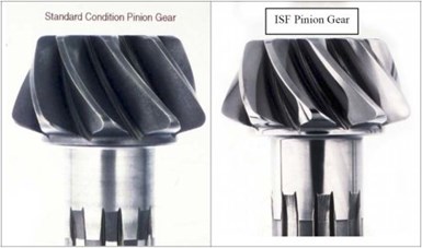
Figure 7 - Comparative results are shown for a pinion from a spiral bevel gearset for (left) a traditional lapped finish versus (right) the same pinion with an ISF finish.
Figure 7 - Comparative results are shown for a pinion from a spiral bevel gearset for (left) a traditional lapped finish versus (right) the same pinion with an ISF finish.
Demonstrated parasitic frictional heat reduction
As noted earlier, engineered metal-to-metal contact surfaces such as gears and bearings transfer energy by mechanical contact. This contact can be a rolling, sliding or pushing force against a complementary component. The asperities on these surfaces introduce friction (i.e., inefficiency) into the mechanical transfer of energy resulting in energy loss which can most noticeably be monitored as heat generation.1-3,5
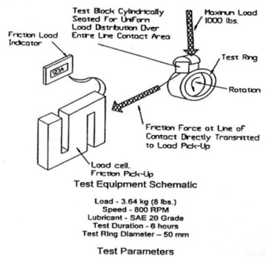
Figure 8 - A simplified schematic of the Block-on-Ring apparatus.3
In a recent evaluation, a major bearing manufacturer monitored the performance features of two functional, metal-to-metal contact surfaces by means of an ASTM D2714 and D2792 Block-on Ring test.3 The Block-on-Ring test rig holds a steel coupon, under constant load, against a rotating ring. The contact interface between the rotating ring and the loaded coupon then becomes an area of experimental interest. (Fig. 8).
In the experiment, a series of steel blocks and rings were evaluated sequentially.3 During each evaluation, the oil sump temperature was monitored as the ring was rotated at a constant 800 rpm. The block was held on the rotating ring under a constant 1000 lb. load.
In the first set of evaluations, the steel coupons were finished using the bearing manufacturer's traditional grinding process to generate a 0.64 μm/25 μ-in surface finish. These samples served as the experimental control standards.3
In the second set of evaluations the steel coupons were ISF-prepared, removing surface asperities and generating the improved ISF (Table 1).3
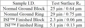
Table 1 - Block-on-Ring Test (Specimen surface conditions)
Concomitant to the mechanical abrading away of the asperities on the ground specimens, was a higher, monitored bearing temperature.3 Additionally, there was a definitive temperature spike of 74°C (165°F), associated with the completion of the loading phase of the break-in cycle on the ground test specimens.3 Once the metal-to-metal contact surfaces of the ground specimens were broken-in (i.e., asperities removed), the monitored temperature dropped to a steady state operational temperature of 63°C (145°F)(Fig. 9).
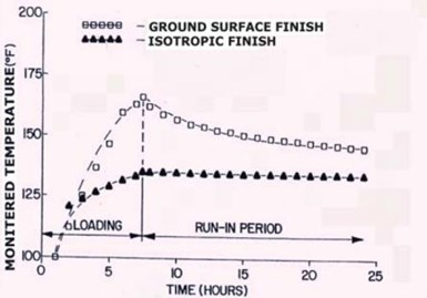
Figure 9 - The temperature curve for normally ground control standard specimens overlaid with the temperature curve for the ISF™ specimens. Note the temperature spike for the ground
specimens corresponding to asperity peak break-in and the absence of a spike for the ISF™ specimens.3 Also, note the lower, final operating temperature of the ISF™ specimens.
Figure 9 - The temperature curve for normally ground control standard specimens overlaid with the temperature curve for the ISF specimens. Note the temperature spike for the ground specimens corresponding to asperity peak break-in and the absence of a spike for the ISF specimens.3 Also, note the lower, final operating temperature of the ISF specimens.
When the testing was repeated using the ISF finished specimens, it was noted immediately that there was a complete absence of the temperature spike, (i.e., no asperity peaks present and therefore no break-in period required). The ISF finished specimens showed a gradual rise to a steady-state temperature, 56°C (132°F).
When compared to the normally ground specimens, this represents a 7.2°C (13°F) difference in final operating temperature. It can be inferred from this experiment that the reduction in operational temperature at the metal-to-metal contact interface indicates a reduction in metal-to-metal friction, thereby allowing this contact interface to retain energy that would ordinarily be lost to frictional heat generation.
Loading efficiency improvement of bearing systems by the ISF superfinish
An evaluation of bearing sets under various loading levels by a second bearing manufacturer confirmed the temperature reduction.2,6,14 Bearing sets evaluated consisted of roller bearings as well as inside and outside races. The evaluation was performed to determine the extent of the possible benefit achieved by ISF™ finishing when applied to complete or partial bearing sets.
As test specimens, the company chose a common bearing set from its traditional line of roller bearings. The testing was performed using three sets of roller bearings that were sequentially mounted in a pillow block.
Test engineers varied the applied load on the bearing sets in the pillow block. Beginning at 1,000 lb. applied load, loading was increased to a maximum of 10,000 lb. applied load. The applied loaded was adjusted upward in 1000 lb. increments.
In each evaluation, the bearing sets were rotated at a constant 2,400 rpm and only the applied load was varied. The pillow block was equipped with a thermocouple to monitor frictional heat generation at the roller/cage interface. Evaluation #1 served as a control standard, and consisted of the company's normally ground roller bearings coupled with normally ground inner and outer races. In Evaluation #2, the rollers were ISF-finished prior to pairing with traditionally ground inner and outer races. Finally, in Evaluation #3, both the roller bearings and the races were ISF-finished prior to testing. The combined results for all three evaluations are shown in Fig. 10.

Figure 10 - Loading efficiency temperature test results for all three bearing sets. 2,6,14
An examination at each loading level shows that the traditionally ground bearing sets consistently had the highest operational temperature (blue columns in Fig. 10).
Bearing sets in which only the rollers were ISF-finished demonstrated cooler operating temperatures at every loading level. At the lower load levels of 1,000 to 3,000 lb., the temperature differential was modest. However, as the loading was increased to the 4,000 lb. level and up, the temperature differential between the Evaluation #1 and #2 samples was significant. Additionally, that differential was maintained throughout the balance of the loading variations (red columns in Fig. 10).
At all load levels and most especially at the higher end loading level of 10,000 lb., the Evaluation #3 bearing sets demonstrated the most significant temperature benefit (white columns in Fig. 10).
The results of this experiment demonstrate that the ISF™ superfinish is a partial benefit, even if applied to selected components in a metal-to-metal, friction induced application. Additionally, the ISF™ superfinish can be of maximum benefit when applied to both complementary metal contact surfaces.
Component durability increase - virtual elimination of contact fatigue
It is a reasonable expectation that ISF, to retain energy by reducing friction, will also increase a component's durability by reducing contact fatigue, asperity stress risers and metallic debris in the lube system. As an example, consider the operational mode of gear mesh. Gears by their nature, undergo two primary modes of motion - rolling and sliding. Rolling motion consists of one gear tooth rolling upon its complementary partner during mesh. Sliding motion occurs when the flank of a gear tooth slides against the opposing flank of another gear tooth during mesh. Sliding occurs both as gear teeth mesh and then again, as they unmesh. Since sliding is a metal-to-metal contact action, it is here that ISF will benefit the gear by reducing contact fatigue problems.
Recently, the Gear Research Institute (GRI) used a Rolling/Sliding Contact Fatigue (R/SCF) Test Rig to evaluate this very hypothesis (Fig. 11).2,7 The R/SCF test rig utilized a crowned, 5" diameter loading roller and a 1" diameter specimen pin (Fig. 12).
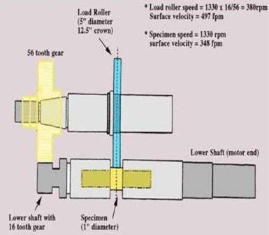
Figure 11 - Simplified schematic of the R/SCF Rolling / Sliding Contact Fatigue Test Rig.2,7

Figure 12 - A 1" diameter specimen pin at the lower left and a 5" loading roller at the upper right side of the photograph.2,7
During R/SCF operation, the 1" specimen pin is secured to a rotating motor shaft. The shaft is in turn connected by two gears to the 5" diameter loading roller. The two components roll against one another during rig operation. The loading roller and the specimen pin have different diameters and the rpm level of the motor shaft on the R/SCF Test Rig can be adjusted by the operator. These differences result in a phenomenon where the specimen pin becomes the sacrificial, friction-affected, sliding wear component.2
During the GRI tests, the R/SCF test operator was able to produce a 43% negative sliding ratio on the specimen,7 whereas, a mid-20% range is typical of normally paired gears. Adjusting the sliding ratio to an artificially high level facilitated having a failure mode on the 1" specimen pin in a minimal period of test time and at a minimal test rig run cost.
Once the rpm level of the R/SCF test rig was optimized, it was maintained as a constant throughout the evaluations. To facilitate specimen pin fatigue, the R/SCF test rig operator varied the stress load with which the 5" diameter contact roller was rolled against the 1" specimen pin. Normal stress loading for the R/SCF test rig is 400 ksi. However, to facilitate accelerated testing, the stress loading can be varied upward. In this evaluation, the stress loads were increased upward in 25 ksi increments to 425 and 450 ksi respectively.7
Two types of sample sets were evaluated during the R/SCF tests. The first evaluations were performed on three sets of rollers and pins. These rollers and pins were the baseline control standard and were prepared to have a traditional ground/honed surface finish typical of the standard surface condition of gear tooth flanks as received from an original OEM manufacturer (Table 2).
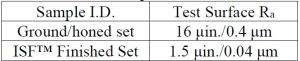
Table 2 - Surface conditions of the R/SCF test specimens.2,7
The second set of evaluations was performed on two sets of rollers and pins. These rollers and pins were ISF-finished to generate the improved isotropic surface using the chemically accelerated vibratory finishing technique described earlier (Table 2).
Prior to beginning the evaluation, GRI defined the test's limitations and specimen performance to determine test completion. Success was determined to be a cycle runout at 20 million rotations of the pin without a failure defined as specimen pin pitting.8 2 To facilitate testing the R/SCF test rig was equipped with a cycle counter to monitor the rotations. Additionally, the R/SCF was equipped with a vibration monitor that would record the onset of pitting by the inception of specimen pin vibration and automatically shut down the test rig to preserve the cycle count.8
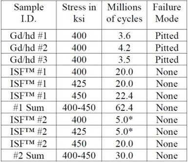
Table 3 - R/SCF test results2,7
Note: Gd/hd = ground/honed
The tabulated results of R/SCF
testing are shown ion Table 3. One should note that, after the extensive time it took to complete the full run outs at all three contact stress levels of ISF™ specimen Set #1, it was decided that when testing ISF™ specimen Set #2, the cycle count would be stopped after 5 million cycles at the lower contact stress levels of 400 and 425 ksi, respectively, to advance to the next highest stress loading level and to save time and reduce cost. The maximum 450 ksi stress
loading level, however, was run to full runout.
In the first set of evaluations, the GRI R/SCF test rig operator was able to generate the typical failure mode of pitting, caused by the significant, applied sliding ratio on the control standard specimens. All three baseline standard samples failed in less than 5 million cycles at the lowest contact stress loading level of 400 ksi. In each case, the failure mode was by pitting.
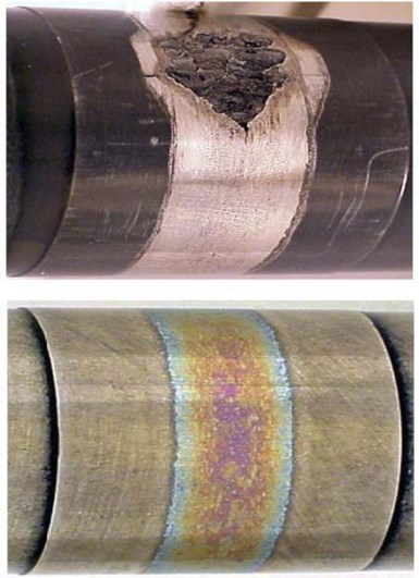
Figure 13 - R/SCF test pin specimen results.
The test results for the ISF™ specimens were exemplary. In fact, the ISF™ specimens could not be made to fail, even with the artificially high sliding ratio and the 450 ksi contact stress load. It should be noted that the initial ISF™ roller and pin set ran for a total accumulated cycle count of 62.4 million cycles. This included 20 million cycles at 400 ksi, 20 million cycles at 425 ksi and 22.4 million cycles at 450 ksi before the test rig was shut down for another test project.
The photographs in Figure 13 compare the results for two of the finishes. The upper photo shows the ground/honed specimen #3 with severe pitting failure mode after 3.5 million cycles at 400 ksi load level. The lower photo shows the ISF-processed specimen #1 after 62.4 million cycles, with no failure and no pitting.
Testing was repeated with ISF specimen set #2 to determine if the favorable results were repeatable.2,7 The test was abbreviated to 5 million cycles at the 400 and 425 ksi stress loading levels so as to reach the maximum loading pressure of 450 ksi quicker. Five million cycles was chosen for the abbreviated, lower ksi loading, runout limit because it was itself, a longer cycle life than exhibited by any of the three sets of failed control standard, ground/honed specimens.
Conclusions
Grinding and honing are traditional surface finishing procedures applied to engineered metal-to-metal contact surfaces such as gears and bearings. Since these techniques are mechanically applied, they leave a final unidirectional pattern on the surface of the part, visible as parallel rows of asperities.
The presence of asperities results in:
- Reduced contact efficiency1,2,6,7
- Friction caused by peak-to-peak contact2,8
- Increased contact stress in the peak-to-peak contact areas2,8
- Heat generation due to friction14
- Loss of energy horsepower transfer through these inefficiencies6
- Shortened component life due to contact fatigue wear and pitting6,7
- Metal debris in the lube system6,7
Chemically accelerated vibratory finishing offers an efficient way to mass-produce an ISF on metal-to-metal contact parts.1,2,4,6,7,11,12 The ISF is random and asperity free.1,2,6,7
Since the asperity peaks have been wiped by the media during the ISF finishing process, the ISF part has no contact fatigue initiation sites. Additionally, metallic asperity debris isn't present in the lubricant stream.2,8
The ISF offers several advantages to the operation of the metal-to-metal contact surfaces:
- More efficient metal-to-metal contact1,2,6,7
- Removing asperities diffuses surface contact stresses by spreading them across a larger surface area.2,8
- Reduction of parasitic, frictional, heat generation14
- Efficient energy transfer2
- Increase in component durability via a reduction of contact fatigue failure6,7
- Elimination of metallic debris in the lubricant recirculation system6,7
References
1. W.P. Nebiolo, "Isotropic Finishing of Helicopter and Turboprop Gearbox Components," Proc. 37th AESF Aerospace/Airline Plating & Metal Finishing Forum, Portland, Oregon (2001).
2. W.P. Nebiolo, "The Reduction of Parasitic Friction in Automotive Gearbox and Drive Train Components by the Isotropic Superfinish," Proc. SAE/PRI Conference, Indianapolis, Indiana (2002).
3. H.P. Nixon & J.D. Cogdell, "Performance Evaluation of a Potential New Engineered Surface for Enhanced Concentrated Tribological Contacts," Proc. SAE International; 1998 Earthmoving Industry Conference and Exposition, Peoria, Illinois (1998).
4. J. Arvin, Arrow Gear; A. Manesh, Power Transfer System Manufacturing; M. Michaud, G. Sroka & L.Winkelmann, REM Chemicals Inc., "The Effect of Chemically Accelerated Vibratory Finishing on Gear Metrology," Proc. AGMA Technical Conference (2002).
5. F.F.H. Hashimoto, R.S., Zhou & K. Howlett, "Bearing Surfaces with Isotropic Finish," U.S. Patent 5,503,481 (1996).
6. L. Winkelmann, M. Michaud, G. Sroka, A.A. Swiglo, & D. Mahan, "Chemically Accelerated Vibratory Finishing for the Virtual Elimination of Wear and Pitting for Steel Gears," American Gear Manufacturers Association Meeting, Detroit, Michigan, (2001).
7. L. Winkelmann, M. Michaud, G. Sroka & A.A. Swiglo, "Impact of Isotropic Superfinishing on Contact and Bending Fatigue of Carburized Steel," SAE International Off-Highway Congress, Las Vegas, Nevada (2002).
8. R.S. Zhou & F. Hashimoto, "A New Rolling Contract Surface and "No-Run-In," Proc. ATLE/ASME Tribology Conference; Maui, Hawaii (1994).
9. R.D. Britton, C.D. Elcoate, M.P. Alanou, H.P. Evans & R.W. Snidle, "Effect of Surface Finish on Gear Tooth Friction," Proc. STLE/ASME Tribology Conference, Orlando, FL (1999).
10. R.W. Snidle, H.P. Evans & M.P. Alanou, "The Effect of Superfinishing on Gear Tooth Profile" Report 2284; contract N68171-96-C-9043 (1997).
11. M. Michaud, F. Tirendi & R.G. Zobbi, "Method for Refinement of Metal Surfaces," U.S. Patent 4,491,500 (1985).
12. M. Michaud, "Metal Surface Refinement Using Dense Alumina-Based Media," U.S. Patent 4,818,333 (1989).
13. R.D. Kane & J. Maldonado, InterCorr International, Inc., Report L99825GK (1999).
14. Technical Bulletin, "Heat Generation Test Results for REM Processed Bearings versus Standard Spherical Roller Bearings," REM Chemicals, Inc., Southington, Connecticut.
About the author

William P. Nebiolo
William P. Nebiolo received a B.A. degree from The University of Connecticut and an M.S. degree from Long Island University. Bill began his metal finishing career at Union Hardware Div. Brunswick Sporting Goods as a plating lab technician. After 2-years at Eyelet Specialty Co. as a plating foreman, 5-years at Nutmeg Chemical as the laboratory director and 3-years at The Stanley Works Corporate Laboratory as chief electrochemist, Bill accepted a position at REM Chemicals, Inc. in Southington, CT as a sales engineer in 1989. He remains at REM to this day, currently serving as Sales Engineer for REM's Midwestern Sales Territory and as REM’s Product Manager.
He joined the NASF as a member of the Waterbury Branch of AES in 1978. Working his way through the branch officers’ chairs, Bill served as Waterbury Branch President 1984-85 and was appointed Branch Secretary in 1991. Bill spearheaded the merger of the Waterbury, Bridgeport and Hartford Branches into the Connecticut Branch in 2004, then petitioned and was awarded branch certification through AESF National. Bill was immediately appointed Connecticut Branch Secretary and remains in the role to this day. He has represented the Connecticut Branch as an NASF National Delegate, has served as a technical chair at several NASF SUR/FIN technical sessions was awarded an NASF National Award of Merit in 2010 and in 2012 was elevated to the position of Connecticut Branch Honorary member. He served on the NASF Technical Advisory Board for many years, becoming the Chair in 2021.
To date, Bill has published a dozen papers in assorted technical journals and presented more than 20 papers at technical conferences and seminars. From 1996 – 2000 Bill served as one of SME’s Mass Finishing Technical Training Program instructors at more than two dozen training sessions. Bill is the author of the SME Mass Finishing Training Book and the REM Training Manual which is now in its 8th edition.
* Corresponding author:
William P. Nebiolo
REM Chemicals, Inc.
325 West Queen Street
Southington, CT 06489
Phone: 860-621-6755
RELATED CONTENT
-
Electroless Nickel Coatings: Appearance, Gloss and Surface Morphology
For decorative coatings, appearance is the essential purpose for application, but also for functional surface finishes it becomes increasingly relevant as an added value on top of specified technical requirements. Appearance is affected by spectrum and intensity of incident light, roughness and morphology of the coating surface, optical properties of the coating material, eventual superficial oxide films, and individual perception. The predominant factor is surface roughness, which in turn depends on base material roughness, quality of substrate pretreatment, and nucleation and growth kinetics of the electroless nickel (EN) deposit. Interdependency of gloss measurements with roughness measurements and with chemical composition of coatings was investigated for new generation mid-P EN processes and compared to traditional ones.
-
A Protective Decorative Electrolytic Coloring Process for Aluminum
The main task of this work was to study the influence of the different parameters on the electrolytic coloring process for aluminum.
-
Methods and Formulas to Determine Internal Deposit Stress in Applied Metallic Coatings
Internal stress exists in electroplated and chemically applied metallic coatings. This paper reviews the test procedures for measuring deposit stress and the formulas used to calculate stress values. Many formulas used require modification to obtain actual internal stress values. Errors in this regard are examined and common mistakes are explained.


