
Preparation for Electroplating
What you should know about cleaning and electrocleaning.
#basics
Share
Imposing a controlled electric current on parts in an alkaline cleaning solution is called “electrocleaning.” It’s done by connecting parts to an electrical lead from a rectifier while they are immersed in the alkaline cleaning solution, thus producing electrochemical effects. The procedure is widely used in preparing parts for electroplating.
Electrocleaning pretreats parts for both rack and bulk processing. It removes soils from everything—from thumbtacks to coil-processed, 48-inch reels of steel. Today’s technology allows us to employ self-regulating, precise voltage and amperage, in conjunction with alkaline solutions. Electrical energy may be applied as direct current (DC), reverse current (RC), periodic reverse (PR) or with interruptions (IR).
Featured Content


Why Clean?
The usual reason for cleaning is to prepare a part for subsequent finishing—electroplating, electroless plating, painting, electrocoating, anodizing, electropolishing, conversion coating and sealing, as examples.
Cleaning should enhance the surface of the part to be cleaned. If not used properly, however, it can impair the surface. You may remove a soil and, in the process of doing this, oxidize or make the surface partially or completely inert. In this sense, you have soiled the surface with a new contaminant! But applied correctly, cleaning can enhance the acceptance of the subsequently applied coating.
A third reason for cleaning is to remove stains, oxide films, etc. Sometimes the process simply enhances cosmetic appeal. Cleaning also can facilitate handling, quality checking, visual acceptance, proper fixturing, etc.
Degreasing is another primary reason for use of any cleaning operation. But for any further surface finishing to be done properly, removal of the film left by degreasing is required. At the same time, you should recognize that, while degreasing is an excellent in-process step and while you may get proper surface preparation in the alkaline cleaner station, it is likely that another step will be required to complete pretreatment for electroplating. The limitations on use of chlorinated solvents for degreasing have increased the value and potential of electrocleaning.
Basis Metals That Can Be Cleaned
It makes life a little easier if we have some general rules of thumb as to what can and cannot be cleaned with various types of alkaline cleaners.
Any alkaline cleaner. Standard alkaline cleaners can be used on steels, stainless steels, tool steels, alloy steels, copper, nickel, nickel alloys, titanium, zirconium and lead/tin without causing a “cure worse than the disease” situation.
Inhibited alkaline cleaners. These solutions contain chemicals that prevent unwanted reactions with metals or alloys in the presence of the caustic -(OH) radical. Such chemistry is required for cleaning brass, bronze, zinc and its alloys, aluminum and its alloys, and tin—the metal itself or as plated.
Acid. There are many acid cleaners that work well in cleaning such metals as magnesium.
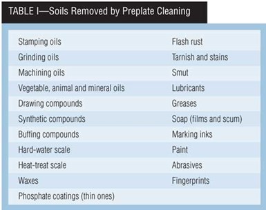
Cleaning processes must be tailored to handle the type of soils expected on a given part. Table I lists many soils that finishers must remove. By no means is this a complete list. But suppliers of cleaning chemicals must know what soils you are trying to remove.
Soils are generally classified as either organic or inorganic. Organic soils include oils and waxes, and redeposited soils. Inorganic soils may range from heat-treat scale, oxide films and pickling smut to polishing compounds and abrasives to shop dust.
What’s in a Cleaner?
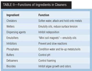
Alkaline cleaners commonly contain carbonates, borax, sodium metasilicates, phosphates, synthetic detergents and surfactants. These chemicals have specific functions, as noted in Table II. Carbonates are added for pH control and buffering. Sodium metasilicate, as a dispersant. Phosphates, for water softening and sequestering. Borax, for buffering and dispersing. Synthetic detergents (“mini soil magnets”), for wetting, emulsifying, complexing, chelating and as biocides. Surfactants come with positive charges (cationic), negative charges (anionic) and no charges (non-ionic).
How Clean is Clean?
The definition of “clean” can be broad and flexible or as specific as your needs. The recognition of whether cleaning is an in-process step for preliminary removal of bulk soil or is a final step before a subsequent finishing operation will dictate selection of testing methods for cleanliness. Each test method has different uses in evaluating cleanliness.
Water breaks. If the surface is completely wetted when water rinsed, it is said to be free of water breaks. This is one measure of cleanliness. Many cleaners have low surface tension, however, and thus small areas of soil can be bridged over. A mild acid dip will neutralize the cleaner, and then a water rinse gives a truer picture.
Wipe. Using a fresh, clean, towel to wipe surfaces will show soils and smut remaining on the surface to be finished.
Part production. Producing parts that are uniform in appearance and/or have an adherent finish is another measure of cleaning effectiveness. But note that this is not always an indication of a properly precleaned part. Sterile operating-room implements, for example, might not take a coating uniformly because they are covered with dead germs. By definition, the germs are a soil.
Immersion copper. The ability of a copper sulfate solution to immersion deposit a uniform copper deposit on steel is an excellent “back-up” test, if there are any doubts.
Reflectivity. Reflectivity of a clean surface versus a “filmed” surface is an excellent tool in the hands of an experienced person.
Electricity for Electrocleaning
The essential parts of an electrical system for electrocleaning are 1) a source of low- voltage direct current, such as a rectifier; 2) conductors, such as cables or bus bars, to carry the current from the source to the racks of parts; 3) rheostats to control the voltage and amperage; 4) a volt meter to measure the potential; and 5) an ammeter to measure the current.
Electrical energy usually travels through utility transmission lines as 60-cycle alternating current at relatively high voltage—3,300 V or higher. But before electrical energy is used, a step-down transformer reduces the potential to 110 V for household use, or to 220 or 440 V for industrial.
To obtain the direct current (DC) needed for electrocleaning, you must “rectify” the alternating current (AC) to direct current and “transform” it from 220 or other voltage to 6–24 V. The most commonly used devices for this purpose are rectifiers.
Rectifiers. Today’s basic rectifier has five sections: 1) an AC power transformer; 2) an AC to DC rectification system; 3) power regulators; 4) controls; and 5) cooling. Overly simplified, the rectifier and transformers convert high-voltage AC to low-voltage DC. This is done using “semiconductors” that allow passage of current in one direction but not in the other.
If an alternating current comes to a semiconductor, only that half of the current that flows in the proper direction will pass through the boundary. The result is a current that is not continuous but pulsating . This is known as half-wave rectification.
If both sides of single-phase AC are rectified so as to pass in the same direction, the resulting curve represents full-wave single-phase rectification.
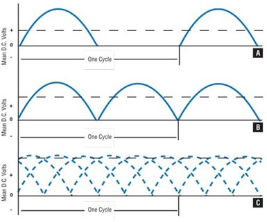
Typical rectification curves: half-wave rectification; full-wave, single-phase rectification; full-wave, three-phase rectification.
It is preferable and customary to rectify three-phase AC with full-wave rectification. This yields a curve that is full-wave, three-phase rectification. There is a ripple (variation) of less than 5 percent in voltage, occurring at a frequency of 360 cycles per second. This electrical current is entirely satisfactory for electrocleaning.
Tank design and anode/cathode placement are just as important in electrocleaning as in electroplating. If you can’t dislodge the soil in certain locations as positioned on a rack you are probably facing similar problems in depositing adequate electroplate thickness in these areas.
Current conductors. Copper is nearly as good a conductor as silver, and it is extensively used for conducting electricity. Aluminum has approximately 60 percent of copper’s conductivity and can be substituted. For short runs (up to 20 feet), not more than 1,000 A should be carried for each square inch of cross section of copper. For longer distances, the rule of thumb is not more than 750 A for each square inch. For example, a copper bar 2 × 1/4 inch has a cross section of 1/2 square inch and will carry 500 A for short distances and 375 A for longer distances. A round copper bar 1 inch in diameter has a cross section of 0.7854 square inch, and it could carry 800 A or 600 A for longer distances.
Aluminum has a resistivity 1.64 times that of copper. Therefore it is necessary to use a correspondingly larger cross section to carry a given current. For example, a cross section of 1.64 square inch of aluminum should be used to carry 1,000 A. When using aluminum bus bars, consider protecting the aluminum from the corrosive attack of alkaline cleaning solutions and fumes, particularly in areas near the cleaning tank.
When joining runs of bus bar, good, tight, clean connections are vital, regardless of whether the bars are copper or aluminum. Resistance caused by poor or dirty connections or contacts retards the flow of current and causes overheating. As heat is generated, resistance builds up proportionately, requiring more voltage to push current through, which in turn causes still more heat, thus multiplying the resistance.
Bus bars may be sized on the basis of temperature rise, voltage drop or energy loss. In electroplating, the usual basis is voltage drop. You can use insulated, flexible copper cable instead of rigid copper bus. The cable is available in a number of sizes, and sometimes in two colors—black for the negative (cathode) conductor and red for the positive (anode) conductor. The insulation may be polyvinyl chloride that passes aging requirements and has the ability to function at temperatures as high as 194°F. This PVC also offers excellent resistance to acids and alkalies. A 1-inch-diameter cable does not have a solid cross section, thus the size of the cross section is not a good guide. Instead, actual current-carrying capacity may be based on temperature rise. Temperature rise is affected by whether the cable is sleeved or bare, run in open air or placed in a conduit, and if in a conduit, the number of cables in that conduit.
Some General Rules
The voltage required for electrocleaning depends on the solution formulation, current density required, temperature, anode area and the anode-to-cathode distance. If the solution concentration is too low and you are using the recommended voltage, you can generate so much oxygen in the high-current-density areas that rusting of the part surface will result. Some general rules:
- 0–6 V rectifiers are satisfactory for applications requiring 30 asf, but 9-V rectifiers are preferred.
- 0–9 V units are necessary for applications requiring more than 30 asf.
- 0–18 V rectifiers may be necessary when the racking area is extremely large or if the anode-to-cathode spacing is wide. For all bulk (barrel and basket) work, this higher voltage level is required.
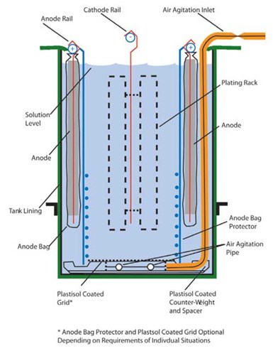
Tank design for electrocleaning racked parts.
A general guide for the anode-to-cathode distance is one volt for each inch of distance. Rule of thumb: a 1- × 4-inch, 1/4-inch-thick copper bus will carry 1,000 A. Another rule of thumb—above 1,000 A, you will be generating heat, not conductivity.
To carry the current from the rectifier to the tank, the copper bus bars and anode and cathode hooks should be designed to carry amperage that will produce slightly more than the highest current density expected. Use tight, clean connections (brazed or soldered joints, or Bellville washers with bolted connections) to reduce the resistance to current flow and the resultant overheating.
Salts (from fumes) can and will accumulate at the bus bar/hook interface. These salts can actually build to the point of breaking the electrical circuit. Set up a maintenance schedule to clean contacts regularly.
Preparing Parts for Electroplating
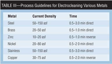
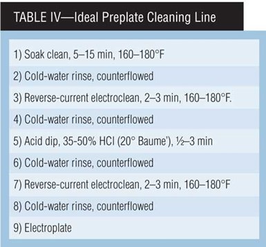
The function of the electrocleaner is to prepare the part for steps to come. Table III provides general electrocleaning current density and time guidelines for a variety of metals. (The more exotic alloys being used by automotive, aircraft and space manufacturing should include input from a metallurgist.) Table IV presents an “ideal” preplate electrocleaning process.
Cleaning includes activating the part’s surface, which is usually done by using reverse-current electrocleaning (the work is made anodic). The terms “anodic” and “reverse” clean are often used interchangeably.
For anodic cleaning, the parts being cleaned are connected to the rectifier’s positive lead while in an alkaline electrocleaner solution. Low voltage (3–12 V) is the norm. Current densities vary from 10 to 15 asf, depending on the metal being cleaned and cleaning time allowed. Cleaning times of 1/2 to 2 minutes generally suffice for most applications. Higher current densities may be used when cleaning times are shorter. At the interface of the anodic part’s surface and the solution, oxygen is liberated. The scrubbing of these gas bubbles assists in soil removal.
Whenever possible, anodic electrocleaning is desirable for final cleaning, because the metal surface is actually being dissolved as well as cleaned. This action removes metallic smuts and prevents the deposition of non-adherent metallic films and particles. Hydrogen embrittlement also is avoided by using anodic cleaning.
Parts marred by heat treating, welding or other sources of oxides often may require a double-cleaning cycle, depending on the degree of oxidation. A mineral acid dip usually follows the final cleaner to neutralize the alkaline film on the metal surface.
To avoid etching and tarnishing, you should control current density, temperature and cleaner concentration, particularly when processing non-ferrous metals. In processing brass and zinc die castings, avoid prolonged reverse-current cleaning, high current densities, high temperatures and low cleaner concentrations, to prevent dezincification and over-etching. Reverse-current alkaline cleaning is not recommended for aluminum, chromium, tin, lead or any metals that are soluble in alkaline electrocleaners.
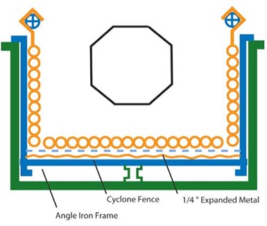
Tank design for electrocleaning parts in a plating barrel.
Cathodic or direct cleaning. Connecting the parts to a rectifier’s negative feed makes them cathodic. The same equipment, voltage and current densities specified for anodic cleaning are generally satisfactory for cathodic cleaning. Hydrogen rather than oxygen is liberated at the surface of the work. The volume of hydrogen liberated at the cathode is twice that of oxygen liberated at the anode for a given current density. Therefore, more gas scrubbing is achieved at the cathode than at the anode. For this reason, cathodic cleaning is sometimes employed as a pre-cleaner, followed by anodic cleaning.
The work is actually being “plated” in a direct-current cleaner. Any positively charged material will be attracted to, and may be reduced and deposited on the surface of the part. Metallic films deposited are from ions in the cleaning solution. These films usually are non-adherent, but can be difficult to detect and remove. Such films can cause poor adhesion, roughness and/or staining of subsequently applied electroplated metals. Consequently, direct-current cleaners must be discarded and re-made more frequently than reverse-current cleaners.
Any work negatively affected by hydrogen embrittlement (e.g. spring steel) should not be cleaned cathodically unless adequate steps are taken after processing to relieve the hydrogen. Generally, heat treatment for one hour at 400°F immediately after processing will remove the hydrogen embrittlement effect. Parts with hardness exceeding 40 Rockwell C can be embrittled and must be baked after plating.
Chromium contamination of cleaners is sometimes unavoidable since the same rack is used in cleaning, chromium plating and other electroplating. Direct-current cleaning is more susceptible to staining from chromium-contaminated cleaners than is reverse-current cleaning.
Direct-current cleaning is generally used to clean chromium, tin, lead, brass, magnesium and aluminum, which are dissolved or etched by anodic cleaning. It is also commonly used to clean buffed nickel prior to chromium plating. Anodic cleaning would leave a passive nickel oxide film, which prevents the proper deposition of chromium.
In periodic-reverse (PR) cleaning, the work is made alternately cathodic and anodic, using a current of 6–15 V. PR cleaning in alkaline solutions containing sequestering or chelating agents removes smut, oxide and scale from ferrous metals. When PR is the final electroclean, the parts should leave this station during the reverse-current part of the cycle. Work may be cleaned on racks or in a barrel. Cleaning and scale removal are facilitated by alkaline cleaning solutions containing reducing and oxidizing agents coupled with strong metal chelators. One advantage of PR cleaning is elimination of acid on certain types of work where entrapment of acid allows bleed-out after alkaline electroplating. Oxides also may be removed without danger of etching or development of smut associated with acid pickling.
Interrupted-current (IR) cleaning. The theory behind IR cleaning is a simple one. At the interface of the soil on the part and the cleaning solution, a reaction is occurring. This reaction depletes the concentration of the cleaning chemicals at the interface. By turning off the power momentarily, the reaction ceases and the cleaner concentration is replenished. When the current comes back on, the solution concentration is what it should be at the interface. A typical cycle would be 8–9 seconds with current, followed by 1–2 seconds with power off. This technique is widely used in processes such as electrochemical deburring or machining, electropolishing and electroforming. If a company is using the same power source for cleaning, rather than re-rack, the finisher might use current interruption in cleaning.
Troubleshooting
Polarity. There are easy ways to determine whether a part is cathodic or anodic in an electrocleaner. If steel or copper darkens in a reverse-current cleaner, the part is probably cathodic. Substitute a piece of copper for the work being cleaned. If it brightens instead of darkening, the polarity of the work is probably anodic.
Inert smut. If the inert smut is on the work before it enters the cleaner, work is probably being degreased. Generally, work can be cleaned better and more easily if it has not been degreased. If precleaning is necessary, soak cleaning is less costly than degreasing.
Etching, rust. Steel emerging from the electrocleaner with black edges or rust-like deposits, and die castings coming out etched both indicate that the concentration of the cleaner solution is too low and/or the voltage applied is too high. Too-high solution temperature is also a possibility.
Floating layers. Floating layers on the surface of the electrocleaner solution can be caused by salt-out of surfactants, often the result of exceeding the recommended concentration of cleaner. Or, temperature may be too high, or acid may have been introduced accidentally, lowering the alkalinity of the solution.
Current density. Reduce the number of racks in the cleaner tank to increase current density. If cleaning is satisfactory, reduce the area of the part surfaces being electrocleaned or increase the current. Often, a shorter time at a higher current density will work, whereas a longer time at a lower current density will not.
High voltage, low current. If the current is low and the voltage high, check the condition of the electrodes. Remove any soil from their surfaces. Make sure rack contacts with the bus bar are solid and not insulated by corrosion or soil. Be sure tank bus leads and other junctions are not overheating, which would indicate poor contact or use of an undersized bus. Check that electrodes on both sides of the rack are operating and that there is no other load drawing from the same power source, in effect robbing the current.
Voltage and amperage low. If both voltage and amperage are low, check the AC input to the rectifier. AC may have decreased and thus lowered the DC output. Have an electrician check the rectifier to see whether bridges are worn. If amperage and voltage are apparently normal, check the area of the workload to be sure the current density is within specifications. More area than normal may have been racked, reducing the current density below that required for adequate cleaning.
Rack contacts, bipolarity. Examine the plating rack. Is it constructed to carry adequate current? Are there adequate contacts? If there is bipolar current, change the insulators on the tank.
Foam blanket. Excessive foam can be caused by drag-in of soils that produce soaps, or chemicals that act as wetting or foaming agents. Loss of the foam blanket can be caused by extremely hard water, drag-in of acid in the second cleaner of a double cleaning line, or drag-in of a different cleaner solution that contains an incompatible wetting agent.
Energy and Solution Management
In the area of energy conservation, controlled agitation of solutions in processing cycles is a viable tool. “Eductor” agitation is reported to have increased the functional available amperage by as much as 25 percent in one case. This, in turn, allowed the benefit of an increase in production processing of parts.
The second management tool is filtration. If you clean it in the cleaning station, why carry the soils and oils into following cycle stations? As much as 80 percent of the dragout soils from the cleaner redepositing on parts no longer needs to be removed in the plating station.
Thus, without major disruption of a particular process line, many-fold return of your investment is awaiting your investigation.
RELATED CONTENT
-
Possibilities From Electroplating 3D Printed Plastic Parts
Adding layers of nickel or copper to 3D printed polymer can impart desired properties such as electrical conductivity, EMI shielding, abrasion resistance and improved strength — approaching and even exceeding 3D printed metal, according to RePliForm.
-
Clean Technology Lasers for Coating Adhesion
Laser cleaning systems remove corrosion, grease, residue and existing coatings from metal surfaces quickly, with less preparation and mess than traditional techniques.
-
Vacuum Degreaser Cleans Up a Messy Situation
By replacing its immersion parts washer with a vacuum degreasing system, this machine shop is much more efficient, saving the company money, man hours and the health of the operators.


