Electrodeposited Nickel Composites Containing Diamond Particles
Originally published as J. Zahavi and J. Hazan, Plating and Surface Finishing, 70 (2), 57-61 (1983), this paper was awarded the 1984 AESF Gold Medal for Best Paper published in Plating and Surface Finishing in 1983. The work, methodology and results discussed here remain valuable from a historical standpoint.
Share
by
J. Zahavi and J. Hazan
Israel Institute of Metals
Technion City, Haifa, Israel
Editor’s Note: Originally published as J. Zahavi and J. Hazan, Plating and Surface Finishing, 70 (2), 57-61 (1983), this paper was awarded the 1984 AESF Gold Medal for Best Paper published in Plating and Surface Finishing in 1983. The work, methodology and results discussed here remain valuable from a historical standpoint. A printable version of this paper is available by clicking HERE.
Featured Content


ABSTRACT
Electrodeposited composite coatings (ECC) containing occluded solid particles in metallic matrices have been developed in recent years for various engineering applications. In this work, the relationships between the concentration, size and type of diamond particles in an electrodeposited nickel matrix and the wear resistance and structure of the coating have been established. Particle codeposition was found to reach a maximum and then decrease with agitation Intensity. It also decreased with increasing current density. Maximum wear resistance of coatings was observed with synthetic and natural diamond particles 3 to 6 µm in size. Formation mechanisms are postulated.
Electrodeposited composite coatings (ECC) containing occluded solid particles in metallic matrices have been developed in recent years for various engineering applications. Coatings containing solid particles of carbides,1-4 oxides,2-6 and diamonds7,8 have been developed for better wear resistance or dispersion hardening. Polymers have been codeposited for self-lubrication.9 Occlusion of these particles into the deposit occurred directly in the plating bath, where the particles were kept in suspension during the growth of the coating.
Particle type, concentration, size and distribution in the deposit determine the characteristics and properties of the composite coating. Therefore, it is important to understand the mechanism and characterize the basic parameters affecting the entrapment rate of these particles into the deposit. In this paper, we characterize the relationship of particle size and concentration in Ni-diamond coatings and discuss structure, morphology and wear resistance. The mode and the major factors affecting the codeposition process with nickel also are described.
Experimental procedure
During our study of composite coatings containing natural or synthetic diamonds, current density, particle size/concentration in the plating bath, agitation and cathode configuration were investigated. Their effects on coating structure and composition, surface roughness and wear resistance were examined.
The coatings were formed in a plating bath at 50 ± 2°C containing 400-450 g/L of nickel sulfamate [Ni(SO3NH2)2], 10-15 g/L of nickel chloride (NiCI2•6H2O) and 30 g/L of boric acid at a pH of 4.0 to 4.5. Diamond particles 0.5 to 40 µm in size were dispersed in 800-L batches of plating solution. The particles varied in concentration from 5 to 117 g/L (25 to 583 carat/L) and were kept in suspension either by a magnetic stirrer rotating at up to 360 rpm (expressed in arbitrary numbers ranging from -2 to 6) and changing direction every 5 sec, or by circulating a mixture of liquid and air4 to provide a solution flow rate of up to 3.0 L/min.
The current density varied from 0.5 to 8.0 A/dm2. Cathodes of both vertical and horizontal configurations were made of low-carbon steel (dimensions of 25 × 25 × 1 or 20 ×15 × 1 mm). Rounded specimens 55 mm in diameter were also prepared for electroplating and subsequent measurements of wear resistance. Specimens were mechanically polished, cleaned and degreased either by immersion in hot alkaline solution containing 20 g/L NaOH, 50 g/L Na2CO3, 50-70 g/L Na3PO and 5-10 g/L Na2SiO3, or by rubbing with a MgO suspension. Thereafter, the specimens were washed in water, etched in 5 to 10 percent HCI for 30 to 60 sec, washed in distilled water and dried before being electroplated.
The diamond particles were cleaned before use. Natural diamonds were treated in a hot concentrated solution of sulfuric acid, washed in distilled water and dried. Synthetic diamonds, however, were treated in a hot concentrated solution of sulfuric acid; washed; treated in concentrated nitric acid; washed; treated in concentrated hydrochloric acid; washed; treated again in hot concentrated sulfuric acid; washed in distilled water; and dried before use.
Deposit structure, morphology and composition were examined by optical and scanning electron microscopy (SEM). Particle distribution and concentration were determined microscopically in cross sections and by surface observations. Wear resistance was determined using a Taber wear test under a constant load of 1,000 g with CS-17 abrasive wheels. Wear resistance was expressed as Taber Weight Index (specimen average weight loss per 1,000 revolutions after being exposed to 5,000 revolutions of the abrasive wheels).
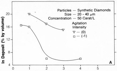
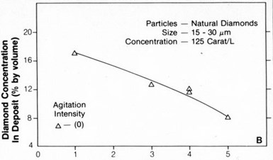
Figure 2 - Concentration of natural diamond particles in nickel deposits as a function of current density.
Effects of current density
Figure 1 shows the relationship between the embedded particle concentration in the nickel deposit and the current density for 20- to 40-µm synthetic diamonds. Figure 2 shows the same relationship for 15- to 30-µm natural diamonds. The concentration of diamond particles in the deposit decreased from values ranging from 15 to 20 percent by volume at a current density of about 1 A/dm2 to 5 to 10 percent by volume at 4 to 6 A/dm2. Typical SEM surface views of deposits formed at 1 and 3 A/dm2 are shown in Figs. 3(a) and 3(b), respectively. They also show that diamond-particle density in the deposit decreased with increasing current density.

Figure 3 - SEM surface micrographs of deposits formed on vertical cathode in nickel sulfamate bath (at 50°C) containing 50 carat/L of 20- to 40-µm synthetic diamonds at (a) 1 A/dm2 and (b) 3 A/dm2. Agitation was intermediate (n = 0).
Agitation effects
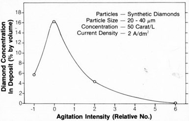
Figure 4 - Concentration of 20- to 40-µm diamond particles in nickel on a vertical cathode as a function of magnetic agitation intensity.
The concentration of synthetic or natural diamond particles up to 40 µm in size increased with increasing agitation (either magnetic stirring or liquid-air) up to a maximum intermediate intensity. This maximum for 20- to 40-µm particles was observed at about 90 rpm with magnetic stirring and corresponds to an intensity of 0 in Fig. 4.

Figure 5 - Concentration of 3- to 6-µm diamond particles in nickel as a function of magnetic agitation intensity.
With smaller, 3- to 6-µm particles, the maximum depended on the cathode configuration (Fig. 5).
A high rate of agitation resulted in a sharp decrease in particle embedment in the deposit. This behavior occurred with both 3- to 6-µm and 20- to 40-µm diamond particles and with either vertical or horizontal cathodes. However, particle codeposition was greater on a horizontal cathode (Fig. 5).
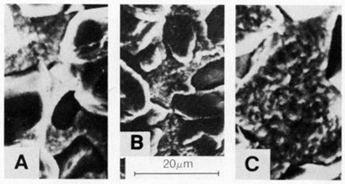
Figure 6 - SEM surface views of deposits produced at 4 A/dm2 in nickel sulfamate solution (at 50°C) containing 125 carat/L of 15-30-µm natural diamonds using: (a) a horizontal cathode and magnetic stirrer at 180 rpm, (b) a horizontal cathode and magnetic stirrer at 360 rpm, and (c) a vertical cathode and magnetic stirrer at 180 rpm.
The SEM views in Fig. 6 show that diamond-particle density on a horizontal cathode was significantly greater than that on a vertical cathode [Fig. 6(c)] using the same formation and agitation conditions. Increasing the agitation from 180 to 360 rpm resulted in decreasing particle intensity, as shown in Figs. 6(a) and 6(b), respectively.
Particle concentration
The effect on particle concentration in the deposit as a result of increasing the concentration of 3- to 6-µm natural diamond particles in the plating solution is shown in Fig. 7.
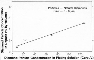
Figure 8 - SEM micrographs of deposit surfaces formed in nickel sulfamate bath (at 50°C) containing 25 carat/L of synthetic diamond particles: (a) 4 A/dm2, 3- to 6-µm particles and (b) 3 A/dm2, 20- to 40-µm particles.
The relationship was linear, as found previously2 with 1- to 2-µm chromium carbide particles. The relationship for diamond particles above 3 to 6 µm in size was not examined in this study.
Both 3- to 6-µm and 20- to 40-µm diamond particles were uniformly distributed in the deposit, as illustrated in Figs. 8 and 9, which show surface views and cross sections, respectively. The entrapment of the particles affected the surface roughness of the coatings, as shown in Fig. 10. Surface roughness increased with increasing particle size, ranging from about 0.2 nm center-line average (CLA) with 0.5-µm particles to 3 to 4 CLA with 20-40-µm diamond particles. Natural diamonds 3 to 6 µm in size caused less roughness than 3- to 6-µm synthetic diamond particles.

Figure 9 - SEM cross sections of nickel deposits formed in a sulfamate bath (50°C) containing 25 carat/L of synthetic diamond particles: (a) 4 A/dm2, 3- to 6-µm particles and (b) 2 A/dm2, 20- to 40-µm particles.

Figure 10 - Surface roughness of nickel electrodeposits containing (S) synthetic and (N) natural diamond particles.
Wear Resistance
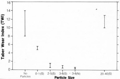
Figure 11 - Wear resistance of nickel electrodeposits containing (S) synthetic and (N) natural diamond particles.
Variations in particle size and concentration in the deposit affected coating wear, as shown in Fig. 11. Wear resistance was highest with 3- to 6-µm natural or synthetic particles. Wear resistance decreased with the use of smaller or larger particles. Furthermore, wear resistance increased with increasing particle content in the deposit (Fig. 12).

Figure 12 - Wear resistance of composite deposits as a function of diamond particle concentration in the plating bath.
Particle Codeposition Stages
Based on the effects of varying particle size, concentration and agitation, three major stages of the particle-incorporation process are characterized below.
Stage 1 involves the transport of suspended particles from the bulk of the plating solution to the cathode surface. During this stage, the mode and intensity of agitation and the cathode configuration are the most important factors affecting the formation of a uniform particle suspension at the interface between the cathode and the plating solution.
Stage 2 encompasses particle adsorption. During this stage, particle adherence to the cathode surface for a critical time period is important. Initial adsorption of particles on the cathode surface is affected by electrostatic forces (attraction or repulsion) developed between the particles and the surface. These forces depend on the type and magnitude of the particle surface charge.
Upon reaching the cathode interface, particles should adhere for a critical time - long enough to permit particle coverage with the metallic matrix - in order to ensure complete engulfment later in the growing deposit. The critical time period is affected by the rate of deposition (i.e., the current density) and the particle size and shape.
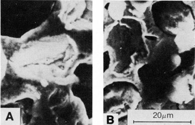
Figure 13 - SEM micrographs showing voids in nickel deposits created by the dislodgement of 20- to 40-µm synthetic diamond particles: (a) deposit at 1 A/dm2 on a vertical cathode and (b) deposit at 1 A/dm2 on a horizontal surface.
Figure 13 shows local cavities where diamond particles adhered initially but not long enough to be sufficiently covered and withstand subsequent dislodgement. Figures 13(a) and 13(b) are SEM views of deposits formed on horizontal and vertical cathodes, respectively.
Stage 3 involves the engulfment of particles by the growing deposit.

Figure 14 - SEM micrographs of nickel deposits illustrating the entrapment mode of (a) 3- to 6-µm synthetic diamond particles on a vertical cathode, (b) 20- to 40-µm synthetic diamonds on a horizontal cathode, (c) 15- to 30-µm natural diamonds on a vertical cathode and (d) 15- to 30-µm natural diamonds on a horizontal cathode.
During this stage, particle conductivity is important. The surfaces of highly conductive particles such as Cr3C2 are plated completely, resulting in the formation of particle agglomerates.1-3 Poorly conductive particles such as alumina and natural or synthetic diamonds are engulfed only at cathode areas adjacent to them. Figure 14 shows how small and large particles become engulfed on horizontal and vertical surfaces.
Maximizing particle entrapment
Because coatings containing a high concentration of diamond particles exhibited improved wear resistance (Fig. 12), electroplating conditions leading to maximum particle codeposition should be adopted. As noted previously, agitation intensity was particularly influential during the first stage of particle embedment into the growing deposit. Increasing the agitation above a critical value resulted in decreased particle incorporation, probably due to the removal of already adsorbed particles on the cathode coupled with a reduction in the number of newly adsorbed particles adhering to the surface - a result of the interfering effect of collisions among particles approaching the cathode. However, decreasing the agitation intensity below the critical value resulted in a decrease in the number of particles reaching the cathode surface and, consequently, a decrease in their embedment rate in the growing deposit.
Increasing the concentration of diamond particles in the solution increased the particle codeposition rate. The linear relationship observed for 3- to 6-µm particles (Fig. 7) was similar to previous findings with chromium carbide particles.2
By increasing the particle concentration in the solution, the number of particles reaching and striking the cathode surface without interference (first stage of codeposition) was increased. However, with bigger, 20-to 40-µm particles, the codeposition rate reached a maximum value and declined thereafter with an increase of particle concentration in the solution.1-3 The maximum corresponded to a situation in which the rate of particles reaching the cathode surface was equal to that of particle embedment in the growing deposit. Increasing the particle concentration above the critical value probably caused the removal of already adsorbed particles on the cathode surface and a reduction in the number of new particles adhering to the surface because of geometrical effects and collisions among the particles approaching the cathode.1
Current density markedly affected the codeposition rate of diamond particles (Figs. 1-3). Like nonconductive alumina,1-5 with an electrical conductivity of 10-13 mho/cm, diamonds7 with an electrical conductivity of 10-5 mho/cm were inhibited in codeposition when the current density was increased. At high current density (i.e., high deposit growth rate), the encapsulation of diamond particles into the growing deposit (third stage of the codeposition process) was very high (Fig. 14). Furthermore, at high current density, the growing deposit rate on particle-free zones on the cathode surface also was high, tending to reduce particle codeposition relative to the number of particles incorporated at low current density. Advantageously, diamond particles (which are nonconductive) are embedded and distributed uniformly into the nickel deposit at both low and high current densities (Fig. 9), as was previously found with alumina particles (nonconductive) but not with conductive chromium carbide particles.1-2
In view of previous reports,9-12 it is assumed that nickel ions are adsorbed on diamond particles suspended in nickel sulfamate solution to give particle surfaces a positive charge. Upon reaching the cathode surface (first stage of the codeposition process), forces of electrostatic attraction between the particles and the cathode result in particle adherence to the cathode surface (second stage of the codeposition process). The particles that remain attached to the cathode surface sufficiently long to become partly covered by the growing deposit at the particle/cathode contact areas (Fig. 14) thereafter become completely embedded in the growing deposit (Fig. 9, third stage of the codeposition process). Although diamond particles of all sizes (3-6 and 20-40 µm) exhibited the same behavior regardless of the agitation intensity or configuration, the critical contact time for the smaller particles evidently was shorter than that for the larger particles under the same electroplating conditions. This was deduced from Fig. 13. Subsequent engulfment of the different particle sizes was essentially the same, as could be deduced from Fig. 14.
The relationships between particle size, wear resistance and surface roughness observed for nickel-diamond composites (Figs. 10 and 11) also were observed during previous studies1,2 with nickel-chromium carbide coatings. In both cases, deposits containing 3- to 6-µm particles exhibited maximum wear resistance and were low in surface roughness. Coatings containing smaller or larger particles were less resistant to wear.
In the case of the coatings containing large particles, wear is initiated by the removal of the particles at or near the surface. Thereafter, nickel wears at a faster-than-normal rate because it contains voids. Codeposition of particles smaller than 3 to 6 µm inhibits nickel matrix wear but to a lesser degree.
The removal of large diamond particles is associated with particle rotation, translation or both. The cutting action involved during particle dislodgement also removes matrix material. Consequently, cavities larger than the particles are produced in the nickel matrix. With coatings containing small particles (3 to 6 µm), the removal of the particles is inhibited because they are too small to undergo rotational or translational movement. However, such particles are large enough to inhibit the removal of the nickel matrix. But the inhibiting action of smaller particles is not effective enough. Therefore, coatings containing particles smaller than 3 to 6 µm (or no particles) exhibit poor wear resistance.
Conclusions
Properties of nickel-diamond electrodeposited composite coatings are affected by particle size and concentration in the nickel deposit matrix. Wear resistance of the coating increases with an increase in particle size, giving maximum wear resistance with 3- to 6-µm diamond particles.
The codeposition rate of either natural or synthetic diamond particles increases with decreasing current density. It increases with particle concentration in the solution and with agitation intensity up to a maximum value, and is followed by a decreasing entrapment rate with a further increase in agitation intensity.
The concentration of diamond particles is higher on a horizontal, rather than a vertical, cathode.
Acknowledgment
The authors gratefully acknowledge the DeBeers Company for providing the diamonds used in this study.
This work was part of an MS thesis prepared by Mr. Hazan at the Technion Israel Institute of Technology. The authors wish to thank Professor Joseph Yahalom for his advice on this work.
References
1. J. Zahavi and H. Kerbel, Proc. Interfinish 1980, 208 (1980); Proc. AES An. Conf., 68 (1981).
2. J. Zahavi and H. Kerbel, Plat. & Surf. Fin., 69, 76 (Jan. 1982).
3. J. Foster and E. Cameron, Trans. Inst. Met. Fin., 54, 178 (1976).
4. E.C. Kedward, C.A. Addison and A.A. Tennett, Trans. Inst. Met. Fin., 54, 8 (Jan. 1976).
5. M. Pushpavanam and B.A. Shenoi, Met. Fin., 75, 38 (Apr. 1977).
6. S.R. Grutza, U.S. patent 3,762,882.
7. D.D. Roshan, IEM Journal of R&D, 22, 681 (Nov. 1978).
8. J. Zahavi and J. Hazan, "Development & Application of Electrodeposited Composite Coatings of Ni Containing Diamond Particles," three Annual Research Reports, No. 041-155, Israel Inst, of Metals, Technion, Haifa, Israel (1979,1980,1981).
9. J. M. Sykes and D. J. Alner, Trans. Inst. Met. Fin., 54, 178 (Apr. 1976).
10. C. White and J. Foster, Trans. Inst. Met. Fin., 56, 92 (1978).
11. T.W. Tomaszewski, Trans. Inst. Met. Fin., 54, 45 (1976).12. J.R. Roos, J.P. Celisand and J.A. Helsen, Trans. Inst. Met. Fin., 55, 113 (1977).
About the authors (as of 1983)

Dr. Joseph Zahavi heads the Corrosion and Surface Treatment Laboratory at the Israel Institute of Metals, Technion City, Haifa, Israel. Dr. Zahavi holds a degree in materials engineering and has written more than 40 papers in the areas of corrosion, anodizing and electroplating. He holds a patent in the field of anodizing and several awards in erosion/corrosion and electroplating.
Joseph Hazan is a graduate student in the Dept. of Material Engineering at the Technion Israel Institute of Technology. He has worked for a number of years in the corrosion/surface-treatment labs of the Israel Institute of Metals. He specializes in composite coatings and holds a BS degree in chemistry.