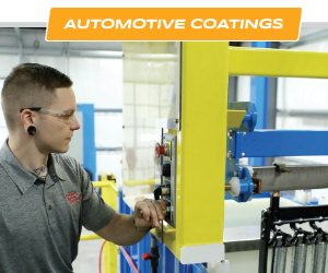
How Does Aluminum Impact Dry Film Thickness Readings?
Jay Kunick from Fischer discusses why different dry film thickness gauges will give different measurements on aluminum, and how to get accurate readings.
#ask the expert #measurement-testing
Share
Q. When it comes to measuring dry film thickness (DFT) over aluminum, especially curved aluminum, I am noticing that I receive vastly different dry film thickness data, depending on which manufacturer makes the DFT gauge I am using. Why would this be the case? What can I do to assure the DFT data I am receiving, over an aluminum substrate, is accurate?
A. Excellent question! First, you are correct in your observation. Many painters are experiencing the same exact issue when comparing DFT data from DFT gauges made by different manufacturers on the same aluminum part. This topic continues to rise to the surface as automotive OEMs continue to increase their volume of aluminum vehicle manufacturing.
Featured Content


There are three possible explanations for what you are experiencing.
1. Calibration or, more accurately stated, verification of accuracy of the DFT gauge
If one “calibrates” a DFT gauge with a flat sample of aluminum, usually provided with the DFT gauge by the manufacturer, and then begins measuring DFT over a part exhibiting curvature, the DFT values provided by that gauge will be erroneous.

As you will see later, the more significant the curve, the more significant the measurement error. If the curve is convex, the DFT reading will be higher than the reality and the opposite is true with a concave curve.
One way to somewhat minimize this curve effect is by calibrating the DFT gauge on a curved aluminum surface, not the flat aluminum sample provided by the gauge manufacturer. This will help to reduce the full effect that the curvature introduces, but it will not eliminate the error! Keep in mind, if the diameter of the curve you are measuring over changes, so will the accuracy of your DFT data.
2. The conductivity changes within the substrate
If the conductivity of the aluminum changes, so will the DFT values. A change in the substrate’s conductivity will affect the measured DFT values. Fortunately, this is seen more often when comparing different batches of aluminum, not within a single part. However, it is possible to experience this effect when comparing different parts on the same vehicle. For example, if you compare an aluminum hood with an aluminum tailgate, each part is manufactured from a different batch of aluminum. It is likely their conductivities will be different. To address this challenge, there are conductivity compensated probes on the market today. Not many DFT gauge manufacturers offer this level of probe technology, but at least one I know of does. For more information, ask your DFT gauge representative if they offer conductivity compensated probe technology.
3. DFT gauge probe is not compensated for effect of curvature
Like the substrate conductivity change, if the radius of the curve changes, so will the accuracy of your DFT values. As I stated above in relation to calibration, the tighter the radius of the curve is, the greater the curve’s effect on the accuracy of the DFT probe and measurement data will be.


Because of this challenge, some choose to take DFT measurements in flat areas only. The problem with that solution is two-fold. First, zero film-build data is being collected in areas that contain curvature. Second, the areas that are curved, especially areas with significantly tight curves, are the locations that tend to have paint chip more easily, exposing the coating layers underneath to the atmosphere and possible corrosion. It is critical that all areas of the vehicle, curved or not, receive the required paint film-build for vehicle appearance and durability requirements.
Unfortunately, there are not many options to fully address this challenge. There is only one. Find and utilize curvature compensated DFT probe technology. Like conductivity compensated probe technology, the curvature compensated probe technology can eliminate the negative effects of part curvature and deliver accurate DFT readings, virtually identical to DFT measurements over a flat substrate. Again, not many gauge manufacturers offer this level of probe technology, but at least one I know of does. The same manufacturer offers a combined conductivity and curvature compensated probe as well. For more information, ask your DFT gauge representative if they offer curvature compensated probe technology.
RELATED CONTENT
-
How to Avoid Orange Peel in Powder Coating
One of the most common quality issues with powder coating is an uneven “orange peel” texture. Bruce Hilbert, applications/technical manager for Tiger Drylac, offers advice for avoiding this common defect.
-
Understanding Paint Atomization
BASF coatings development expert Tim December explains how paint atomization works for both pneumatic spray applicators and high-speed rotary bell applicators.
-
Blistering Defects and How to Avoid Them
Verney Denerville of TIGER Drylac discusses recommendations for avoiding or mitigating blistering defects in powder coatings.