
Looking Back: The Columnists
Many industrial/technical journals consist of a well-rounded mixture of technical papers, practical articles about technology and how-to-do-it features, including this one, Products Finishing. In its decades of publication, the AESF/NASF journal, Plating & Surface Finishing also endeavored to meet this need. Among the many features were those of the columnists, recognized experts who had expertise in certain segments of the surface finishing industry. This article contains a sampling of columns published in P&SF over the years, which still retain information of importance even today.
#nasf

Share
Compiled by Dr. James H. Lindsay, NASF Technical Editor
Fenton, Michigan, USA
Introduction
Featured Content


Many industrial/technical journals consist of a well-rounded mixture of technical papers, practical articles about technology and how-to-do-it features, including this one, Products Finishing. In its decades of publication, the AESF/NASF journal, Plating & Surface Finishing also endeavored to meet this need.
Among the many features were those of the columnists, recognized experts who had expertise in certain segments of the surface finishing industry. Contributors offered articles on decorative finishing, electronics, processes, patents and others too numerous to mention. What follows is a sampling of columns published in P&SF over the years, which still retain information of importance even today.
Unfortunately, given the limitations of space, we left out several of the writers that were very popular back in the day, and to them we apologize. Nonetheless, the seven columns which follow capture the flavor and value of the offerings. A printable PDF version of this report is available by clicking HERE.
ADVICE & COUNSEL
Eductor 101
.jpg;maxWidth=385)
By Frank Altmayer, MSF, AESF Fellow
Originally published as F. Altmayer, Plating & Surface Finishing, 91 (1), 28 (January 2004)
Dear Advice & Counsel:
I have a very simple question. What is an eductor and how can it provide an advantage in our plating operation? We are a captive hard chromium plating facility and we have heard about these devices from some friendly competitors, but even they are not using them.
Signed, Barely Agitated
Dear Ms. Agitated:
Eductors are devices used to amplify water flow by a Venturi effect. Figure 2 is an illustration of an installation from one of the suppliers of these systems. While the most common eductors are made of PVC, they also are made from a number of other materials including cast iron and stainless steel.

Fig. 2 This illustration shows how an eductor works. (Courtesy of SERFILCO, Ltd., Northbrook, IL.)
Eductors can effectively and more uniformly agitate a process tank without producing aerosols. Process tanks are typically equipped with a bank of eductors specifically designed to provide a uniform movement of liquid. This uniform solution movement is accomplished without the production of undesirable aerosols. Further, eductors can improve the quality of electroplated deposits by improving plating uniformity across racked parts on a work bar. Eductors can eliminate or reduce the cooling effect of air blower agitation, minimize brightener breakdown caused from oxidation by air, and reduce the introduction of dust and vapor into the solution.
Additional benefits eductors may provide are:
• More even plating distribution
• Reduction of thermal stratification
• Reduced air emissions
• Reduced tendency to pit in some solutions
• 25% energy reduction in heated tanks
• Operation at higher current densities
• Improvement in throw/coverage
• Broader bright range, lower brightener consumption
• No air blower (less noise)
• No clogged spargers producing non-uniform or absent agitation
The above sounds one-sided, but there are a few disadvantages that must be considered:
• Eductors take up more tank space than an air sparger
• The material of construction for the eductor must withstand the chemicals in the tank
• An electric motor/pump is required to drive an eductor system. With multiple systems, energy costs may increase.
• The mechanical force of the liquid may sometimes cause parts to sway in the tank. This can usually be worked around by the installation design.
Potential uses for eductors are:
Cleaners
Alkaline cleaners function through the use of thermal, chemical and mechanical energy. By increasing any of these three forces, the efficiency of the cleaner is likewise increased. By replacing recirculating pumps or air agitation with an eductor system, the level of mechanical energy applied to parts is significantly increased.
With eductors, there also is less contamination of rack superstructure and contamination of portions of parts protruding from the solution. During my visit to your facility, you indicated that some parts were rejected due to "rundowns". This is where mist or splashes from the cleaner collect on the portion of the parts that reside out of the cleaner (parts are only partially submersed). During subsequent plating processes, the cleaner runs down the part and causes a streak in the plated deposit.
Plating/Anodizing Processes
Hard chromium platers that have switched from air agitation to eductors to maintain tank temperature have provided me with favorable comments on the effect. A nickel plater that replaced air agitation with an eductor system reported a dramatic reduction in air emissions and an improvement in plating speed and distribution. Eductors may improve most any plating process that requires vigorous agitation. An exception may be processes such as acid zinc plating, where air agitation is required to control the iron content.
Eductors may also improve anodizing quality and speed by providing a higher level of mechanical force.
Acid Pickling
The efficacy of an acid can be improved by adding agitation. If the eductor is used to replace air agitation, less fumes and mist will be produced.
Rinsing
I have always had a poor opinion of air agitated rinses, because too often the air comes up in one corner of the tank and the rest of the tank is "dead". Eductors provide a much more effective level of agitation and are not subject to the clogged sparger syndrome.
A word of caution: Always discuss a change in the method of agitation of any plating or anodizing process with your supplier or consultant, before investing in such a change. At times, an eductor system may require a change in additive package (especially wetter) to avoid an undesirable change in appearance.
Frank Altmayer is a Master Surface Finisher and an AESF Fellow who is Technical Education Director of the AESF Foundation and NASF. He owned Scientific Control Laboratories (SCL) from 1986 to 2007 and has nearly 50 years of experience in metal finishing. He began his career with SCL by signing up through an employment agency. Altmayer was instrumental in a research project for a client that ended up revolutionizing how ECG electrodes were made. His reward for this discovery allowed him to buy into SCL in 1992. Since then, Frank has been a consultant and became technical education director of the AESF Foundation and NASF, where he has taught electroplating courses for over 40 years. He contributed his column, Advise and Consent, longer than any other columnist for P&SF.
THE REAL WORLD OF CORROSION
Corrosion Testing: Natural Environments
 By Richard G. Baker, CEF
Originally published as R.G. Baker, Plating & Surface Finishing, 75 (1), 16 (January 1988)
Corrosion testing. Ah, the very words conjure up visions of extensive travel to exotic environs. Perhaps a South Sea Island! Wouldn't that be an ideal corrosion test site? Well, I'm here to tell you that while South Sea Islands are unique from the standpoint of their natural beauty as well as from the aspect of corrosion, the weather may be more than you bargained for.
Every year, I used to go to a tropical island in the Pacific and I had occasion to talk about my experiences there. After all these years, I can still remember that I could taste the salt in the air even when I was on top of a three-story building! Consequently, I entitled my talk "The World's Largest Salt Spray Chamber."
For the purposes of corrosion testing, natural environments can be conveniently separated into industrial, marine, rural, arid or desert, and tropical. There are also natural environments that encompass more than one type. For example, New York City is an industrial environment that contains some marine-borne contaminants because it is close to the ocean.
The corrosion rate of a metal will vary depending on the type of environment to which it is exposed. Table 1 shows that the rate at which zinc is attacked in two highly industrialized environments - New York City and Altoona, PA - is significantly higher than that in the other settings. It is important to recognize that other metals may show completely different corrosion rates when tested in these same environs.
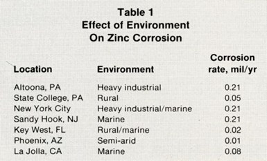
Table 1 – Effect of Environment on Zinc Corrosion
Exposure Conditions
When exposing plated or painted test panels to natural environments, the most frequent observations, as a function of time exposed, include: (1) a change in coating appearance, (2) the advent of base metal corrosion products, (3) pitting of the finish and (4) panel weight loss or gain. In addition, when painted panels are exposed, an "X" is often scratched through the coating to the basis metal and the progress of corrosion at that intentional void is observed, again as a function of time.
Exposure to natural waters (e.g., sea water) is also used to evaluate materials from a corrosion standpoint. Exposure may involve full, partial or periodic immersion. Intermittent inspection permits a determination of the effect of exposure time on the metal or metal combination being tested.
There are also corrosion tests performed by burying candidate materials in various types of soil. Yes, soil not only gets your hands dirty, it may also cause corrosion. Depending on the type of soil and the material exposed to it, severe corrosive attack is a possibility.
Time Considerations
It should be recognized that corrosion testing in natural environments normally takes longer than in simulated settings, where accelerated tests are employed. In addition, a single type of natural environment may vary in its "corrosivity" as a function of the time of year. Again, considering New York City, the relative humidity is usually fairly low during the winter months but generally quite high in the summer. Plated and other panels will therefore experience higher corrosivity rates during the humid months, in this case.
Not only is the average and maximum relative humidity likely to differ from one period of the year vs. another, but prevailing winds may come from a different direction, or the type and amount of corrosive contaminant in the environment may vary. In addition, the relative humidity or temperature excursions between day and night can play an important role in the degree of corrosion that occurs, as can other seasonal variations. Suffice it to say that most natural environments are rarely static and may contain a number of potentially corrosive contaminants that, in combination, may aggravate the condition of a particular test specimen.
At this point, let's return to that South Sea Island (wouldn't we all love to!). Here, of course, we have what appears to be an ideal marine environment. However, there may also be decaying vegetation or marine life around that could contribute additional corrosive contaminants to our idyllic island atmosphere. While the predominant corrodant may be the salt-laden air, the presence of these other materials may change the magnitude of the corrosion that arises.
Test Setup
Static or rack corrosion tests are generally the most popular of the atmospheric exposure types. These consist of exposing the specimen at a specific angle to the horizontal. In addition, the specimen (or actual workpiece) is normally exposed at some designated angle with respect to magnetic north. The positioning is largely dependent on the type of corrosion information desired and previous experience with the particular test site.
To prevent unwanted galvanic coupling with any metallic rack material or mounting hardware, the test panels or actual parts are mounted in such a way that they are electrically isolated. Visual inspections are made periodically, and multiple specimens are frequently exposed simultaneously. This permits the periodic removal of a specimen, which can then be evaluated more conveniently in the laboratory both visually and for any weight gain or loss data that may be needed.
Since we all have a tendency to be a little impatient, we normally want more rapid answers to our corrosion tests. To answer this need, and as a result of the relatively long time required to run natural environmental corrosion studies, a large number and wide variety of accelerated tests have been developed. These generally aim to produce rapid results without adversely affecting the type of corrosion product that would form in a natural environment.
Richard G. Baker was associated with the Electrochemical Research and Development Department of the Bell Telephone Laboratories for many years. He was supervisor of the Corrosion Engineering, Metal Finishes, and Contacts Group. Mr. Baker attended Rutgers University and took graduate work on electrical contact theory at Pennsylvania State University. He served on the AES Research Board and was a member of the Allentown-Reading Branch of the American Electroplaters Society. He was instrumental in developing the CEF program. In retirement, he served the AESF in several capacities over many years.
DO’S AND DON’TS
Hydrogen Embrittlement from Plating Processes

Originally published as D. W. Baudrand, Plating & Surface Finishing, 94 (2), 20 (February 2007)
Do's and Don'ts to minimize and/or eliminate hydrogen embrittlement from high strength steels, copper alloys or other alloys.
What is hydrogen embrittlement? How does it form? What is the mechanism, i.e., how does it take place? Why does hydrogen cause embrittlement? I really do not know the answer to the preceding four questions. There are numerous scientific papers dealing with these questions. I have read many of them over time and I still don't know. An excellent paper was given by Dr. Chris Raub1 when he received the AESF Scientific Achievement Award at AESF SUR/FIN 1993, entitled "Hydrogen in Electrodeposits: Of Decisive Importance, But Much Neglected."
What I do know is that hydrogen embrittlement can cause catastrophic failure of high strength steel and other alloys. The failure is usually in the form of cracking or complete separation. It can also cause blisters in both the basis metal and at the plating interface, reduced ductility, internal voids and lower yield strength.
What steels are subject to hydrogen embrittlement? I have found controversy about this. In general, high-strength steels, including "low alloy steels" and some stainless steels are vulnerable. Often steels susceptible to embrittlement are related to their tensile strengths. Dini2 indicates that steels with tensile strength values of 1240 to 2140 MPa (180,000 to 310,000 lb./in2) are susceptible to embrittlement. Other references indicate risk above 1100 MPa (160,000 lb./in2). In general, the higher the tensile strength of the steel, the more susceptible it is to hydrogen inclusion and embrittlement. Even austenitic alloys are susceptible. Maraging high-strength steels with tensile strengths of 2740 MPa (397,000 lb./in2) have higher susceptibility to hydrogen embrittlement.
In an article by Paatsch,3 ultra high strength steel fuse holder rings of C75 (German standard DIN 471) and were plated in various plating solutions and under a number of different preparation cycles. The results and conclusions are interesting. The processing used was as follows: an alkaline cleaner; followed by pickling in 12% HCl-inhibited acid for 0 to 600 seconds; followed by plating. The deposits studied included zinc plating in eight different zinc plating solutions, Watts nickel, sulfamate nickel, cyanide copper and acid copper. There were failures using a modified constant load test derived from ASTM F 519.4
A summary of the results shows that all of the samples using 60 sec or more pickle time failed at time intervals of up to 24 hr heating at 220°C (428°F) regardless of the plating solution used. Some samples required 70 hr of heat treatment after plating, to pass the tests. The samples that used less than 60 sec of inhibited HCl pickle showed no failures at all, regardless of the type of plating solution used.
A note about electroless nickel and hydrogen
Electroless nickel (EN) generates hydrogen as a part of the deposition reaction. Therefore, hydrogen embrittlement of high-strength steels can occur. What is different about electroless nickel deposits, you ask? Remember that electroplated deposits are crystalline. That is, they have grain boundaries from which hydrogen can escape during the baking process. Electroless nickel is virtually amorphous (without grain structure). Since there are no grains, it is very difficult for hydrogen to pass through electroless nickel deposits, particularly thicker deposits where there is little or no porosity.
How then, can hydrogen relief take place? Sometimes EN deposits over 25.4 μm (0.001 in.) thick will crack on heat-treating at high temperatures or at low temperatures for long times. Hydrogen can then escape. But we usually do not want cracks because they may induce cracks in the basis metal. Another method is to mask a non-critical area so that there is an unplated area from which hydrogen can escape on baking. Also baking should start at very low temperature for a long time, followed by a gradual increase in temperature to the recommended level. EN deposits with thicknesses of 25.4 μm (0.001 in.) or higher are very likely to crack if heated to 300°C (572°F) or above. The cracking is due to the reduction in volume as the nickel phosphorus changes to crystalline (Ni3P).
What did I learn from all this coupled with many years of experience? Here are a few precepts to consider:
Do's
- Do be aware that hydrogen embrittlement can cause serious failures.
- Do use appropriate heat relief of entrapped hydrogen. The time and temperature combination must be such that tests prove no failure.
- Do test very soon after plating, one to three hr. Test another baked sample after many hours.
- Do realize that the bake time and temperature required to do the job may be much more than the standards ask for. Always test.
- Do use solvent degreasing, alkaline soak cleaning or anodic alkaline cleaning (if required for specific soils).
- Do use inhibited acid for pickling, if pickling is really necessary. Not all inhibitors work well. Test the results.
- Do consider shot grit blasting, vibratory cleaning and shot peening. Shot peening is good for lowering the surface stress.
- Do consider alternative coating processes such as mechanical plating of zinc, Ti-cad or other suitable metals. There is also powder coating to consider.
Don'ts
- Don't assume that just because you followed the recommended post plating bake cycle that the hydrogen is removed sufficiently to pass the tests.
- Don't use strong or non-inhibited acid pickles.
- Don't use the same bake cycle for electroless nickel deposits unless there is an unplated escape area on the part.
- Don't rely on a simple bend test shortly after plating. Bend tests are not reliable for hydrogen embrittlement determination. There is no reliable quick test.
- Don't use cathodic preplating treatments. A nickel strike for activation of stainless and other nickel-containing alloys may be required. Be assured that there will be significant infusion of hydrogen. A longer than usual bake cycle may be required.
References
1. C.J. Raub, Plating & Surface Finishing, 80 (9), 30 (1993).
2. J.W. Dini, Electrodeposition, The Material Science of Coating and Substrates, Noyes Publications, Park Ridge, NJ, 1993.
3. W. Paatsch, Plating & Surface Finishing, 83 (9), 70 (1996).
4. ASTM F 519-06, Standard Test Method for Mechanical Hydrogen Embrittlement Evaluation of Plating/ Coating Processes and Service Environments, ASTM International, W. Conshohocken, NJ, 2006.
Mr. Don Baudrand, CEF was an independent metal finishing consultant, based in Poulsbo, Washington, since 1994. He received his B.A. in Chemistry from Whittier College, California and did Graduate Work at the University of California – Berkeley. From 1954 to 1966, he was Owner and President of Electrochemical Laboratories, and until 1994, was Vice-President at Allied-Kelite. He was a member of several professional associations including NASF, the International Microelectronics and Packaging Society, SME, SAE and the Institute of Metal Finishing. He held ten U.S. patents and numerous foreign patents and authored over 70 published papers.
FACT OR FICTION?

The Precautionary Principle
By Jack W. Dini
Originally published as J.W. Dini, Plating & Surface Finishing, 89 (7), 36 (July 2002)
• Better safe than sorry.
• Just in case.
• Above all, do no harm.
• Do nothing new until it can be absolutely proven to be completely safe.
All of the above statements have been used to describe the precautionary principle (hereinafter referred to as PP). Few policies for risk management have created as much controversy as PP, which emerged in Europe in the 1970s and is now in environmental statutes and policies - including the margin of safety requirement for setting ambient air quality standards under the Clean Air Act, the Rio Declaration from the 1992 Earth Summit, and industrial practices involved in product testing and environmental management.1 Yet, despite its seemingly widespread political support, PP has engendered endless controversy, in part because of the confusion surrounding its interpretation.
One legal analysis identified 14 different formulations of the principle in treaties and nontreaty declarations.2 The "strongest" formulation of the principle can be interpreted as calling for absolute proof of safety before allowing new technologies to be adopted. The World Charter for Nature (1982) states that "where potential adverse effects are not fully understood, the activities should not proceed." Foster, et al.,2 points out that if this is interpreted literally, no new technology could meet this requirement. Some PP formulations open the door to cost-benefit analysis and discretionary judgment, while still others call for decisions in the absence of any scientific evidence at all.
If the stronger PP criteria were followed, something as common as salt or pepper or sugar or Vitamin D could never be added to prepared foods. Any of these might be carcinogens to which everyone is unavoidably exposed - the last three have, in fact, been shown to cause cancer in at least one animal test.3
Application of PP decades ago to innovations (such as polio vaccines and anti-biotics) might have prevented occasionally serious, and sometimes fatal, side effects by delaying or denying approval of those products. That precaution would have come at the expense of millions of lives lost to infectious diseases, however.4
PP is about risk, and life is risk. If you want to be a strong advocate of PP in your daily living, perhaps you should not even get out of bed in the morning, because as soon as you do this, you take a risk. Even if you decide to stay in bed, you take a risk. About 20 Britons die every year as a result of falling out of bed, while 30 die in their bathtubs. Around 600 die on their own stairs.5
How difficult is it to get dressed? For some people, the answer must be "very." In 1997, some 50,000 close calls were seen by emergency room doctors. A pair of socks can spell disaster. Emergency rooms treat hundreds of sock-wearing accident victims who have slipped and taken bad spills.6 You can choke to death on a lump of health food.5 Risking and living are inseparable (hospitals make people sick; exercise can hurt you; herb tea is laden with carcinogens, etc.). Even breathing, according to a prominent theory in which cancer is caused by oxygen radicals created through the burning of fat, can kill.3
One could go on and on with these types of statistics, and if you want to really capture the spirit of our fearful times, read: I'm Afraid, You 're Afraid; 448 Things to Fear and Why, by Melinda Muse.6 This volume is an A-to-Z compilation that will provide you with enough information to show you there is nowhere to run, nowhere to hide - it's no longer survival of the fittest, but of the wariest. The book is a textbook of life's hazards - from abstinence to zippers, martinis to yard sales, it's all here. Things you must not touch, places to flee, creatures and people to avoid. A must-read if you're a worry wart.
Getting back to PP and its advocates, in recent years, those advocating the stronger definitions of PP have sought to narrow both the information and the choices available for society to make important decisions, ranging from public policy issues, to consumer products and the application of science. This use of a narrowly focused PP has resulted in some devastating adverse consequences. In 1991, Peru suffered a massive outbreak of cholera, which killed 7,000 people and afflicted more than 800,000 others. This was caused by Peru's decision to ban the chlorination of drinking water, based on American studies that had shown there might be a slight chance of developing cancer due to chlorine. But the chances of cancer death from chlorinated water turned out to be far less than the risk of death due to a contaminated drinking supply.7
Another potential negative impact is the expenditure of large amounts of dollars to correct a problem of limited or negligible impact, thereby leaving less funding for other measures that could be more important. Clean-ups are accomplished only by diverting resources from other worthy missions, including the avoidance of other health risks. For example, putting the $6 billion per year being spent on Superfund toward cancer research would quadruple cancer research spending.8 Estimates put the cost of avoiding one case of cancer through Superfund clean-up at a whopping $11.7 billion."
Another example is lead. Vast amounts of resources have been devoted to cleaning up lead at hazardous waste sites, while more significant sources of lead exposure, such as apartment paint and soil in urban areas, have received less attention.2
PP as a guide to decision-making under conditions of uncertainty suffers from another drawback. If the future is really all that uncertain, how can one be confident that action taken today will not make things worse, rather than better? For example, if effective action had been taken in the late 1960s and early 1970s to combat the fear, widespread among certain climatologists, that the world was entering a new Ice Age, the consequences now would have been most unfortunate.10 These are the same folks who now promote global warming. Stayed tuned. Who knows what our weather folks will be telling us 20 years from now.
Summary
PP is fundamentally a statement of values related to beliefs about how organizations and society ought to operate. When combined with other desirable societal characteristics - such as sustainable development, investment in science and technology, science-based decision making and expanded consumer choices - PP can add an important dimension to the choices of civil society.1
However, reformers must understand and effectively communicate five simple truths about risk regulation to convince the public that regulatory reform will result in more protection, not less:7
1. Not every risk is avoidable.
2. All risks are relative.
3. Wealthier is healthier.
4. Regulations can have adverse side effects, thereby creating more risk and less protection.
5. More lives would be saved if risks were prioritized.
Application of PP makes sense - if it's done with the above in mind. Policymakers who rely on the strong definitions of PP, however, turn a blind eye toward the risk created by over-regulation. This is a costly mistake. For much of the world, the greatest environmental threats are derived from poverty and a lack of innovation, not new-fangled technologies. By focusing on only those risks posed by the uncertainties of new technologies, PP turns a blind eye to the harms that occur, or are made worse, by the lack of technological development."
References
1. T.F. Yosie, "Science-Based Decision Making at The Crossroads," Annual Meeting for Risk Analysis, Washington, DC (December 4, 2000).
2. K.R. Foster, P. Vecchia & M.H. Repa-choli, Science, 288, 979 (May 12, 2000).
3. A. Wildavsky, "Trial & Error Versus Trial Without Error," Rethinking Risk & the Precautionary Principle, J. Morris, Editor, Butterworth Heinemann (2000).
4. H.I. Miller & G. Conko, "Genetically Modified Fear & the International Regulation of Biotechnology," Rethinking Risk & the Precautionary Principle, J. Morris, Editor, Butterworth Heinemann (2000).
5. J. Brignell, Sorry, Wrong Number, Brignell Associates (2000).
6. M. Muse, I'm Afraid, You're Afraid; 448 Things to Fear and Why, Hyperion (2000).
7. J.C. Shanahan & A.D. Thierer, "How to Talk About Risk: How Well-intentioned Regulations Can Kill," The Heri¬tage Foundation, Report No. 13 (April 23, 1996).
8. Cutting Green Tape, R.L. Stroup & R.E. Meiners, Editors, The Independent Institute (2000).
9. D. Mastio, "Reform Speeds Toxic Clean-ups," The Detroit News, May 9, 2000.
10. W. Beckerman, "The Precautionary Principle & Our Obligations to Future Generations," Rethinking Risk & the Pre-cautionary Principle, J. Morris, Editor, Butterworth Heinemann (2000).
11. J.H. Adler, "Better Safe Than Sorry?" Intellectual Ammunition, 8, 6 (Nov./Dec. 1999), The Heartland Institute.
Jack Dini earned a Bachelor of Metallurgical Engineering degree from Cleveland State University and began his career in the 1950s with Cleveland Supply Co. (now Pavco). He spent a few years at Republic Steel's research center and Battelle Columbus Laboratories. In 1962, he joined Sandia Laboratories, Livermore, CA, where he was involved with electrodeposition projects for 18 years before moving to Lawrence Livermore (LLNL) in 1980. He was section leader, fabrication processes. Responsibilities included direction of activities in five groups: electroplating and metal finishing, vacuum processes, metal fabrication, plastics and optics. He is the author or coauthor of some 180 technical papers and, while many researchers are content to specialize in one or two fields, he made significant contributions to more than half a dozen disciplines in surface finishing. He is the author of two books, Electrodeposition- The Materials Science of Coatings and Substrates, and Challenging Environmental Mythology: Wrestling Zeus. The scientific community is fortunate that he carefully documented his work, sharing it with others around the world. It includes plating uncommon metals, alloy plating, printed circuits, chemical milling, electrojoining and gathering electrochemical/property data.
CIRCUIT TOPICS

The Future of Circuit Board Manufacture
By Dr. Alan M. Poskanzer
Originally published as A.M. Poskanzer, Plating & Surface Finishing, 72 (12), 18 (December 1985)
The PC board industry is severely recessed at the moment and there are a lot of concerned folks. Not to worry - the future is going to be bright because it holds new and exciting technology. Those who are "with it" will share the bright future. The current recession is merely a blip on our time line. History dictates that our industry is cyclical and that we are now merely in a trough. The crest of the wave is coming and this next one indeed will have some very nice features.
Where are we going and why? Appropriately, let's close 1985 by peeping into our crystal ball. As I see it, there are three driving forces for future developments: (1) surface-mount technology, (2) a need for more simple and perhaps dry processing and (3) environmental protection.
Surface Mount
As usual, there is a need for smaller PC boards. We are forever demanding lighter and more compact electronic systems. Miniaturization has had an enormous impact on our industry for years. In that respect, little is changed. It seems as though the more we can do with a smaller device, the more we want it. It is logical.
A grand engineering development in the PC field is surface-mount technology (SMT). It is just what the name implies - mounting components directly to conductor pads on the PC board without the use of mounting holes.
Surface-mount devices are becoming more widely available. SMT allows boards to be fabricated with fewer and much smaller holes. Furthermore, the holes need not be at the conductor ends with pads. They can reside along the traces because they are used as via contacts only. The methodology has profound implications on the design of circuit boards. Most notably, the boards will be much smaller with the same circuit.
SMT will represent a large part of the industry within five years. The Technical Marketing Research Council of the Institute for Printed Circuits (IPC) has estimated that 40 percent of the world's PC boards will be SMT types by 1990. SMT will require superior imaging systems with higher resolving power, as well as different forms of chemical processing to build boards with finer lines and smaller holes.
Simple Processing
Even with SMT, PC boards nowadays are becoming tremendously intricate and therefore require process control and engineering almost beyond our capabilities. The point is best made using a realistic example.
Imagine a circuit board with about 20 inner layers. The overall thickness is about 0.180 inches. There are some holes as small as 0.018 inches (10:1 aspect ratio). Moreover, some inner layers are of 2-oz copper foil while others are ½ oz. The holes must be desmeared after drilling and this is accomplished using a permanganate treatment process.
The first problem occurs when the resin in certain layers is bifunctional FR-4 while other layers contain the so-called tetrafunctional resin. This causes various layers to be etched back to varying degrees (differential etchback). Furthermore, due to the presence of ½-oz material, the residence time in the electroless pre-etch can be only 15-30 sec to prevent excessive attack on the small inner layers.
Such a panel requires processing with very narrow operating windows, and, in short, it is barely possible to build such a board. Requirements for chemical processing are becoming more stringent all the time and there are limits. One way to solve such problems is to use fresh approaches - whole new ideas. New processes must be more easily controlled with fewer steps and broader operating latitudes.
Environmental Protection
The third driving force is the ever-increasing need to prevent harm to our environment through the discharge of chemical waste. Suppliers to the PC industry are very sensitive about this issue and are feverishly trying to find ways to satisfy these requirements.
There is a lot of effort toward finding ways of dealing with chemical waste for existing processes - and necessarily so. However, there is also considerable effort being expended to invent chemical processes that produce either more easily treated waste or none at all.
This driving force, coupled with the requirements for simpler processing, is resulting in unprecedented challenges on chemical suppliers to come up with new technology.
I can think of four areas of technology whose time has come. In fact, I'll now go out on a limb by predicting that these technologies will find increasingly broad use over the next several years. Here they are:
1. New Imaging Systems: As circuit trace dimensions continue to get smaller and SMT becomes increasingly popular, the limitations of dry-film photoresist will be tested more frequently. There is also renewed activity and technology being made available in the area of liquid photoresists.
Liquid resists can be applied in much thinner films and are available in positive-working systems as well as negative (that is, they develop away where exposed). Positive-working photoresists, due to their chemical nature, are inherently superior in resolving power. In fact, positive resists are widely used to make integrated circuits. Two years ago in this column, we stated that the PC industry would be borrowing technology from the chip manufacturers. This is one area where that is happening. For higher-density, surface-mount, finer-line boards, dry-film photoresist may become obsolete.
2. Semi-Additive Processing: This type of PC processing has been a sleeper for years. Bare, unclad laminate is drilled, plated with electroless copper, imaged and pattern electroplated. It is similar to the standard subtractive process except that unclad laminate is used. The only drawback is that adhesion of the electroless copper to the resin surface must be enhanced in some way.
Assuming that it is enhanced, the advantages of semi-additive are enormous and do address the driving forces discussed above. First, semi-additive obviates the need for deburring - no copper foil, no drilling burrs. Second, there is far less copper to etch away at the end (0.05 mil of electroless vs. 1.5 mil of 1-oz clad foil). Due to such a low thickness of background copper, the fine-line capability of semi-additive processing far exceeds that of the standard subtractive method.
3. Bright Tin: Bright tin plating has been construed as having limitations, but the technology has now been improved. Due to the growing use of bare copper circuit boards with solder mask (SMOBC), there is a lot more solder stripped nowadays and far more lead-containing spent solder stripper disposed of. Due to the obvious environmental impact, this cannot continue.
One of the most favorable solutions to this problem is to eliminate lead by plating 100 percent tin instead of 60 percent tin/40 lead. We don't need to worry about the tin growing "whiskers" because it is only an etch resist, which is stripped anyhow.
4. Electroless Replacement: The electroless copper deposition process has been around for years and has been refined, improved and "perfected." Still, to this day, there remains a six-step process that is somewhat intricate chemically. It is frequently a source of problems to the PC shop and of high service to the vendor. Due to the complexity of PC boards now being fabricated, process operating windows are becoming narrower, resulting in more problems and more service. The industry is becoming ripe for something entirely new that is easier to use and has fewer steps and a broad operating latitude.
Such technology is likely to become available in some form simply because there is a need, there is room for improvement, and there are many brilliant minds around who would love to make obsolete the electroless copper process. Any takers?
Well, now that you've heard my predictions ... just sit back and wait!
Dr. Alan M. Poskanzer received his B.S. in Chemistry in 1969 from Clarkson College of Technology, Potsdam, NY. He remained at Clarkson where he received his M.Sc. in Physical Chemistry in 1971, and his Ph.D. in 1974, majoring in Physical Chemistry and minoring in Colloid and Surface Science. While at Clarkson he was an affiliate member of the Institute of Colloid and Surface Science. Following receipt of his Ph.D., Dr. Poskanzer began his working career at the Shipley Co. Inc., Newton, MA, as Senior Research Chemist.
FINISHER'S THINK TANK

Spray Cleaning - Do It the Right Way
By Stephen F. Rudy, CEF
Originally published as S.F. Rudy, Plating & Surface Finishing, 89 (7), 38 (July 2002)
Organic finishes, such as painting and powder coating, have become more popular, based on factors such as:
• Consumer demand;
• Product styles; and
• Corrosion protection.
Finishing operations, based on the type of coating application, may incorporate these benefits: waste minimization, recycling, and easier waste treatment. The importance of spray cleaning as part of these finishing cycles in the surface preparation of metals has become more evident. If the base metal surface has not been sufficiently cleaned in the first step, subsequent conditioning (e.g., phosphatizing) followed by organic coating, will certainly fall below desired quality. Spray cleaning incorporates the benefits of mechanical action and chemical reaction, effectively removing oils, grease, smuts and other soils related to the manufacture and fabrication of parts. Doing it right means spraying it right, thereby cleaning it right. Let's review some considerations for spray cleaning, with suggestions and troubleshooting tips.
Parts
"Parts is parts" - a sometimes-heard line, is a gross misstatement. Parts are unique, based on factors such as their make-up, alloy, surface condition or heat treatment. Steels may be hot or cold rolled. Mechanical forming drives oils and metallic shavings into the part surface. Heat treating bakes and bums oil and grease into surface pores, while also forming oxide scale. Mass finishing may leave media residue or compounds from chemical processing on the surface. Storage time of parts and atmospheric humidity may accelerate rusting. These are some concerns with regard to knowing the alloy of metal, method of fabrication or machining, heat treating and initial surface treatment. Understanding what's been done to the parts we have helps to develop an effective cleaning cycle.
It's common to have a mix of products or variety of parts designated for organic finishing in the same process line, or equivalent cycle. Aluminum, brass, copper alloys, steel, stainless steel and zinc may be run interchangeably. Often, individual parts may be fabricated using mixed metals or alloys. These concerns affect the chemistry of the cleaner, along with the cleaning demands or requirements.
Fixturing or Racking
Parts are exposed to the impact of mechanical spraying of cleaners, rinses, phosphates and any other process solutions. Fixturing or racking of parts should be firm, allow full exposure to treatment solutions, provide for complete drainage of solutions, and minimize entrapment and carryover of solutions. The racks or fixtures should be fabricated from materials compatible to the chemistry exposure, coated with appropriate plastic, vinyl or similar protective coatings. Reconditioning or stripping of rack tips (chemical immersion or oven) should not attack the materials of their construction or coatings.
Spray Cleaner
A variety of ferrous and nonferrous metals, along with alloys and mixed components, are spray cleaned. The critical step of spray cleaning may be conducted off-line, to pre-clean or, as is common, as part of an automatic process line (e.g., three- or five-stage machines). Spray cleaners offer the following benefits:
• Low-foaming cleaning action for dis-placement of soils;
• Mechanical action, which facilitates cleaning;
• Lower temperature ranges, reducing energy use and cost economizing.
Spray cleaning solutions may range in pH from near neutral (6-8) to high pH (14). This enables the use of selected solutions to clean a mix of metals, including aluminum, brass, copper alloys, steel, stainless steel and zinc. Displacement of oils and grease is preferred. The sprayed cleaner is recirculated from a separate tank, usually incorporating mechanical skimming devices, overflow weir, coalescer or membrane filtration. In this way, the soils are continually separated, preventing their redeposition on parts, and lengthening the cleaner service life.
The spray cleaner's active level of surfactants and wetting agents is usually lower than the requirement for an immersion soak cleaner. This is because mechanical spraying significantly helps to remove the soils wetted and loosened by surfactants and wetting agents. The levels of these organic cleaning agents, importance of cloud point (related to surfactants), and incorporating defoamers, contribute to maintaining the important low-foaming characteristics. Water hardness conditioners are very critical to successful spray cleaning. Spray nozzles must be kept free of calcium, magnesium deposits and soap sludges to prevent plug-gage. If it doesn't squirt, it doesn't work.
Liquid and powder spray cleaners are effectively used in many applications. Typical operating parameters are given in the accompanying table.
Some troubleshooting items have been mentioned, and these and additional considerations are given in the following breakdown.
Failure to Adequately Clean
- Concentration of spray cleaner under-concentrated. Adjust as required.
- Solution temperature out of range. Adjust accordingly.
- Insufficient residence time for spray cleaner contact. Adjust accordingly. This may affect overall line speed, and other processes, specifically rinsing and phosphate.
- Chemistry of spray cleaner not sufficient for the specific cleaning requirement. Conduct appropriate evaluation to determine if surfactants and wetters or alkalinity should be changed. Consider separate precleaning of troublesome parts.
- Spray nozzle. Insufficient pressure, plugged, or spray pattern. Adjust pressure, replace or clean plugged nozzles, confirm water conditioner blended into spray cleaner, install spray head delivering desired pattern on parts.
- Redepositing previously removed soils. Service mechanical oil removal devices. Determine if cleaner service life has been exceeded and replace with fresh make up.
- Previously applied coating on parts (e.g., anodize, lacquer, phosphate). Determine °C, Time, min Agitation, psi optimum stripping method, chemical or mechanical.
There is another problem often overlooked. This is the accumulated buildup of organic coatings (lacquers, paints, powder coats) on racks and fixtures. Failure to remove these agglomerated materials has the effect of slowing the speed of conveyorized lines. This may result in or contribute to overcleaning or etching of parts, and usually a reduction in productivity.
Organic finishes, especially powder coating, have become popular for several reasons, including the ones given here. Surface preparation, especially cleaning, critically affects subsequent organic finishing. Spray cleaning is a quick, effective method for removal of surface soils prior to the conditioning step before paint or powder. Spray cleaning - do it the right way.
Stephen F. Rudy, CEF began his finishing career at the Frederick Gumm Chemical Co. in 1983. He was with the Gumm company for over 16 years and went through several corporate acquisitions before landing at Hubbard-Hall, where he spent his last 12 years doing technical support for the company’s many clients. Over his 40+ year career, he has seen and solved many issues that occur in plating operations. Steve graduated with a chemistry degree from Rutgers University and continued with graduate degree studies in chemistry. He achieved his CEF designation soon after entering the metal finishing industry. He has been a prolific author in his career in metal finishing. He authored two chapters in the Metal Finishing Guidebook and Directory, addressing general surface preparation and for specific metal alloys, in addition to acid pickling. He contributed Finisher’s Think Tank to Plating & Surface Finishing for over 10 years
As a corporate Technical Service Manager, Rudy’s product R&D lab and pilot work encompassed cleaning, plating, and post treatments. Additionally, his dedicated research work formulated product development of specialty cleaning processes, environmentally compliant stripping organic coatings, and effective mass finishing systems. He was also a plating school instructor for many years. He was past two-term AESF Garden State Branch President and was on the board of the MAMF.

Progress in Electroforming
By William H. Safranek, CEF
Originally published as W.H. Safranek, Plating & Surface Finishing, 75 (3), 18 (March 1988)
Dating back to 1839, electroforming is older than electroplating. The fabrication of electrotypes for printing Russian bank notes was the first application. The several hundred patents on electrotypes issued since illustrate a progression of improvements in a technology that still thrives. The sophisticated process of electroforming printing plates to produce currency at the U.S. Bureau of Engraving and Printing is one such application that has been described in P&SF (R.H. Williams, Jan. 1987).
But printing plates represent only one of hundreds of electroforming uses cited in the literature. A review that appeared [75] years ago (Plating, 35, 49, 1948) listed more than 50 and described techniques for producing some common articles such as record stampers, molds, reflectors, heat exchangers, paint spray masks, tubing and foil. A few unusual products, including bellows, caskets, dentures, floats and nozzles, also were mentioned.
Many more uses were detailed in a 1962 symposium (see ASTM STP No. 318), which also included particulars on the selection and preparation of mandrels for different applications. Soon thereafter, ASTM B-431 summarized these procedures and has since been updated from time to time to promote electroforming.
Deliberations in the early '60s defeated an attempt to modify the definition of electroforming - the term originally coined by the late Dr. William Blum. The purists insisted that the starting mandrel had to be separated from the deposit before the term could be accurately applied. By contrast, the extremists wanted to include processes that more accurately could be called "electrocladding," where the deposit remains unseparated from the pre-shaped mandrel.
Circuit Foil
Nearly all printed circuit boards use electroformed copper foil, except for a few that employ an additive process. On a tonnage basis, more metal is consumed for this application than for any other. Electroformed foil played a vital role in the development of PWB technology partly because high-purity, pinhole-free foil with the desired thickness and mechanical properties could be made at a lower cost than a melting, casting and rolling process and partly because electroforming was easy to integrate with a surface treatment process that promotes bonding to epoxy boards. The treatment grows a thin layer of leaf-like micronodules and creates laminates with a bond strength several times stronger than those made with rolled stock.
High-speed deposition converts scrap copper directly to high-purity foil. In a variation of the foil production process, predefined circuits are formed on a stainless steel belt patterned with a stop-off and transferred to a flexible plastic coil precoated with an epoxy adhesive. Copper with a thickness of about 0.001 in. is deposited in 1 min.
Structure Fabrication
A report in the October 1966 issue of Plating (p. 1211) summarized the status of electroforming for fabricating load-bearing structures such as pressure tanks, bulkheads, hemispheres, ducts, pipes and heat-transfer cones. Some of these applications required a controlled thickness of only 0.001 in. but others were thicker than 0.5 in. The report discussed the use of "grow-in's," or preformed inserts for strengthening sensitive areas, and the importance of effective electrojoining techniques. Details on shielding and conforming anodes for improving thickness uniformity also were included. Most importantly, the report cited the advantage of a controlled sulfur content in nickel to obtain high strength (up to 200,000 psi) and avoid the notch sensitivity characteristic of nickel containing more than 0.017 percent sulfur.
More detail on techniques for fabricating structures emerged at a 1967 AESF Symposium on Electroforming in Dallas. Cryogenic storage vessels, solar panels, manifolds and special forms of ducting were some examples of new products. Improved methods for making nickel screen and iron foil also were described. An AESF-ASTM symposium in 1974 included reports on combustion chambers, regeneratively cooled thrust chambers, optical parts, heart implantation devices, large space simulators, special channels, seamless belts and other parts.
In the 1980s, an active AESF Electroforming Committee has regularly scheduled sessions on the subject at SUR/FIN conferences. New developments, improved procedures, and successful results have been documented each year. For example, in 1987, ink-jet printing devices, linear accelerator gradients and laser components were the focus of several electroforming reports.
The Future
The authors of many of the reports cited above forecast increasing use of electroforming, and events repeatedly support these claims. The time for explosive growth, surpassing previous expectations, may soon come.
Recent developments that could trigger this explosion include: (1) the confirmed recognition of the role of codepositing manganese to neutralize the harmful ductility and notch sensitivity effects of codeposited sulfur in nickel and its alloys; (2) improved techniques for depositing dispersion-strengthened metals and alloys using submicrometer-sized particles of oxides and carbides; and (3) the demonstrated capability of pulse plating to eliminate or greatly reduce stress and encourage the use of high-strength, high-modulus alloys that cannot be deposited without cracking using conventional DC.
Plating companies with a shrinking business volume due to styling changes or other reasons should think about electroforming. A word of caution is appropriate, however. The relatively crude techniques that once were accepted by purchasers of plated products won't work with electroforming, which is highly sophisticated and requires a thorough knowledge of production techniques and some homework on market potential.
William H. Safranek was Technical Editor of Plating and Surface Finishing from 1977 to 1991. After graduating with a BS degree in chemistry from the University of Chicago, he was employed in the metal finishing industry for many years. He joined the Battelle Memorial Institute in Columbus, OH, as a research scientist in 1945. He became Assistant Chief of the Electrochemical Engineering Division in 1953 and Chief in 1971; he retired in 1977.
At Battelle he conducted or managed several research projects involving the development of property data for electrodeposited metals and alloys. He was a pioneer in the development of electrolytic methods of joining two or more parts of dissimilar materials, in order to avoid undesirable high-temperature effects. His early work broke new ground in the field of corrosion protection. He later managed several projects in fast-rate plating of chromium, copper, gold, nickel and other metals. His electroforming research resulted in a variety of new shapes and forms. He holds 26 patents on which he is named inventor or coinventor and has authored or coauthored more than 100 technical articles.
Mr. Safranek was the recipient of the 1979 AESF Scientific Achievement Award, recognized as the highest honor given by the society. In 1984 he received the Simon Wernick International Award for achievement and leadership in surface finishing from the International Union for Electro-deposition and Surface Finishing. He has also received several awards for papers presented at AESF conferences. During his involvement with AESF, Mr. Safranek served on several committees, the Board of Directors, and held national office as Second Vice President, First Vice President, and President. He received the Proctor Memorial Leadership award in 1969.
RELATED CONTENT
-
Conversion Coatings: Phosphate vs. Zirconium
Both phosphate-based and zirconium coatings have their advantages, but zirconium is fast becoming the pretreatment of choice.
-
Top Reasons to Switch to a Better Cleaning Fluid
Venesia Hurtubise from MicroCare says switching to the new modern cleaning fluids will have a positive impact on your cleaning process.
-
Cleaning Prior to PVD/CVD Coating
Determining the cleanliness and chemical de-coating of PVD/CVD layers.


