
Smart Modeling and Simulation of Electroplating Systems for Real-Time Monitoring of Chemical, Water and Energy Consumption (NASF Summer Research Grant)
An AESF Foundation summer research grant provided an excellent opportunity for a PhD student to learn how to use chemical engineering fundamentals to scientifically characterize an electroplating process through integrated dynamic modeling and simulation, and how to develop digital twin (DT)-based virtual plant that can be of any process configuration. This is a critical step for the investigation of new technology development for smart and sustainable manufacturing in the surface finishing industry.
Share
Read Next

by
Yinlun Huang*
Department of Chemical Engineering and Materials Science
Wayne State University
Detroit, Michigan, USA
Editor’s Note: This report is a progress report covering the results of a Summer Research Project funded by the NASF-AESF Foundation over a ten-week period (June 1 to August 9, 2022) at Wayne State University in Detroit. A printable PDF version of this report is available by clicking HERE.


1. Student information
Mahboubeh Moghadasi, a Ph.D. student in the P.I.’s research lab, was hired to conduct full-time summer research for this project under the P.I.’s direct supervision between June 1 and August 9, 2022. The student is also financially supported in part by the P.I.’s grant from the National Science Foundation.
2. Project objective
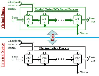
Figure 1 - Digital Twins-based electroplating process scheme.
As stated in the original proposal, this project was intended to train a Ph.D. student to learn the Digital Twin (DT) technology and use it to develop a virtual electroplating plant as a platform for future study on smart manufacturing. The project scope is depicted in Fig. 1. In the project, the student was to be guided by the P.I. to reorganize the fundamental mathematical models that were developed in the P.I.’s lab in the past, integrate the models to form a set of DTs, identify key coefficients in each model for future online adjustment using real-time data, and then simulate the models to study chemical, water and energy consumption for improved manufacturing in an effective manner.
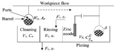
Figure 2 - Sketch of a general plating line.
3. Research activity and accomplishment
Figure 2 shows a simplified plating process, which consists of: (1) a cleaning-rinsing system that can include different soaking, electrocleaning, and acid cleaning units, followed by two or more steps of rinsing after each type of cleaning, and (2) a plating system that contains a plating tank followed by one or two steps of rinsing. The student’s modeling and simulation was made under different process configurations.
3.1 Accomplishment 1 – Generation of integrated fundamental models for cleaning, rinsing and plating, and identification of key parameters in models.
The student reviewed all the fundamental models that were developed by the PI’s lab in the past and reorganized them as follows.
3.1.1 Integrated cleaning model
In a cleaning tank of any type, chemicals are consumed to remove different types of dirt from the surface of parts. The chemicals are partially lost through drag-out. The amount of dirt on the parts is negatively proportional to a dirt removal rate, which is determined by the type of chemicals used and their concentrations and the type and amount of the dirt on the parts. The dirt removal model has the following form:
(1)
(2)
(3)
where Ap is the total surface area of the parts in a barrel (cm2); WPc is the amount of dirt on parts (g/cm2); t is time (min); rPc is the dirt removal rate in the cleaning tank (g/min); γc is the looseness of the dirt on parts (cm2•gal-soln / gal-chem•min); Ca is the chemical concentration in the cleaning tank (gal-chem/gal-soln); γ0 is the kinetic constant (cm2•gal-soln / gal-chem•min); toc is the time when the barrel enters the cleaning tank and α is a constant.
The chemical concentration in each cleaning tank changes during the cleaning operation. The relationship is modeled as:
(4)
where Vc is the capacity of the cleaning tank (gal-soln), and η is the chemical capacity coefficient for dirt removal (g-dirt/gal-chem).
3.1.2 Integrated rinsing model
A plating line has several rinsing steps, each of which may contain more than one rinsing tank. The amount of dirt on parts in a rinsing tank is negatively proportional to the dirt removal rate. The cleaner the rinse water, or the dirtier the parts, the faster the dirt removal. This can be described by the following model:
(5)
(6)
where WPr is the amount of dirt on parts when the barrel is in a rinsing tank (g/cm2); rPr is the dirt removal rate in the rinsing tank (g/min); kr is the mass transfer coefficient (gal-chem•gal-water / gal-soln•cm2);γctec is the looseness of dirt on parts when leaving the cleaning tank at the time (cm2•gal-soln / gal-chem•min); θ is the unit conversion factor (cm2/gal-water) and xr is the pollutant composition in rinse water (g/gal-water).
The quantity of pollutants in rinse water is related to the rinsing efficiency, water flow rate, the initial dirtiness of the parts, and the cleanness of the influent rinse water. In each rinsing tank, there are two operational modes: the rinse mode, during which the parts are submerged in the tank; and the idle mode, where the parts have been withdrawn while the rinse water continuously flows. The following model is derived:
(7)
where Vr is the rinsing tank capacity (gal-water); Fr is the rinse water flow rate (gal-water/min) and zr is pollutant concentration in the influent rinse water (g/gal-water).
After the parts in the barrel are withdrawn from the rinsing tank, the tank will be in the idle mode. Rinse water, however, still flows through the tank. This will lower the pollutant concentration in the tank to the level ready for the rinsing for next barrel. The model for this mode is:
(8)
3.1.3 Integrated electroplating model
An alkali zinc plating case studied by the P.I.’s group before is adopted in this project. The dissolved zinc dynamics needs be simulated. The concentration of the dissolved zinc is determined by the rate of dissolution at the anode and the rate of deposition at the cathode, i.e.,
(9)
where VE is the volume capacity of the plating tank (L); CEZn is the concentration of Zn2+ in the plating tank (mol/L), Ra is the current efficiency of the anode; Rc is the current efficiency of the cathode; 𝔉 is Faraday’s constant (96,485 C/mol) and i is the current density (A/m2).
According to Faraday’s law, a simplified coating thickness dynamic model is derived for zinc plating:
(10)
where δ is the coating thickness (m); t is time (s); ρ is the zinc density (kg/m3) and M is the molecular weight of zinc (kg/mol).
Significance. These models are the modules that can be used to construct a plating line of any number of cleaning, rinsing and plating configurations. When real-time data is available, the models become digital twins (DTs) to form a virtual plant.
3.2 Accomplishment 2 – Model based simulation.
The student conducted a very significant number of simulations for different plating line configurations under various operating conditions.
Type I - Base case. The purpose of this simulation was to test each type of model, and thus a system
was constructed with one cleaning tank, one rinsing tank and one electroplating tank. It was aimed to analyze the effect of chemical concentration settings and operational times for cleaning and rinsing to satisfy the parts surface pretreatment requirement for the electroplating step.
Type II - One step rinsing followed by two-step rinsing, single barrel of parts.
Type III - Cleaning and rinsing of multiple barrels of parts in one production shift.
Type IV - One step cleaning with no chemical addition, two-step rinsing, multiple barrels.
Type V - One step cleaning with chemical addition, two-step rinsing, multiple barrels.
Each type of cleaning and rinsing simulation was followed by simulation of plating operation. For brevity, we report the simulation results of Type V configuration below, as it was the most sophisticated.
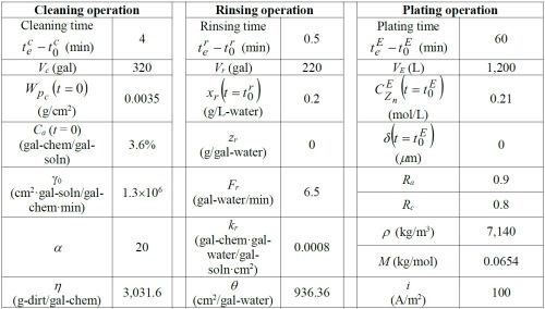
Table 1 - Simulation parameters for the base case.
3.2.1. Optimal result for Type V.
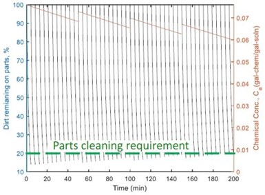
Figure 3 – Dirt removal form the parts in each of 48 barrels where four chemical additions occurred in the cleaning tank.
The simulation in Type V indicated that the last barrels were not clean enough in the cleaning tank. To solve this problem, an optimal chemical addition policy was developed, which included calculation of the time and the amount of chemicals to add. As shown in Fig. 3, chemicals were added every 50 min in operation, and the amount of chemicals added was 60% of the chemical consumption of the first 12 barrels. This guaranteed cleaning quality, meanwhile minimizing chemical loss to the succeeding rinsing system through drag-out. This also reduced the pollutant concentration in the rinsing system, thereby reducing wastewater treatment cost.
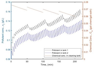
Figure 4 – Pollutant concentration in the two-step rinsing system when the chemicals were added four times in the cleaning tank.
Figure 4 shows how pollutant concentration changes occur in the first and second rinsing tanks using the optimal chemical addition polity. Figures 5 and 6 provide a comparison of the dirt remaining on and the dirt removed from the parts of each barrel after the two-step rinsing operation. All of these provide key information on how to calculate the minimum amount of fresh water needed for addition to the rinsing system, while ensuring the parts rinsing quality, as well as the loading of wastewater to the wastewater treatment facility in plant.
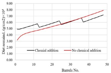
Figure 5 - Comparison of the dirt remaining on the parts in barrels after rinsing with/without periodic chemical addition.
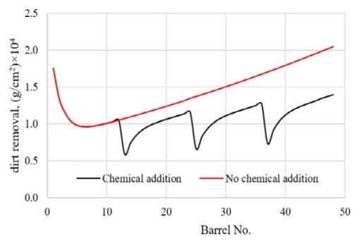
Figure 6 - Comparison of the dirt removed from the parts in barrels after rinsing with/without chemical addition.
The student also simulated a zinc plating process using the models in Eqs. (9) and (10.
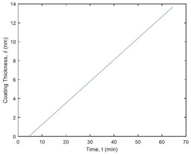
Figure 7 – Coating thickness dynamics on parts in each barrel.
Figure 7 illustrates the dynamics of zinc deposition on parts during operation. It shows that the coating thickness is 13.67 nm after 60 minutes. The thickness specification is 12 nm. The research also revealed that the plating time could be reduced to 53 min, which led to 11.8% of reduction in the amount of zinc produced (221.8 g).
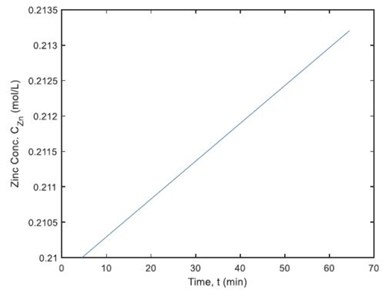
Figure 8 – Zinc concentration dynamics in an electroplating tank.
Figure 8 shows that the concentration of zinc in the plating tank is increased to 0.2132 mol/L, which results in 251.3 g zinc produced after 60 min of plating. This preliminary study provides a specific guideline for controlling plating operations that could not only meet the coating quality requirement, but also save operational time and thus improving productivity.
3.3. Accomplishment 3 - Model parameter identification for artificial neural network (ANN) based realtime parameter determination.
The student has identified a number of parameters in the models shown in Eqs. (3), (4), (6) and (7), which need to be updated using real-time data, in order to develop a reliable digital twin (DT) based virtual plant. These include the looseness of the dirt on parts, the chemical capacity coefficient for dirt removal, and the mass transfer coefficient, depending on the type of chemical used, the shape of the parts to be cleaned and rinsed, and the type of dirt to be removed.
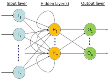
Figure 9 – A basic structure of a recurrent neural network.
A general approach in model fitting is to select an objective function. This would be very important for eventual development of ANN models like that shown in Fig. 9 for real-time adjustment of those key parameters in the DT’s. This task will be part of the student’s Ph.D. study in the future.
4. Summary
The summer research grant from AESF provided an excellent opportunity for the PhD student to learn how to use chemical engineering fundamentals to scientifically characterize an electroplating process through integrated dynamic modeling and simulation, and to learn how to develop digital twin (DT) based virtual plant that can be of any process configuration. This is a critical step for the investigation of new technology development for smart and sustainable manufacturing in the surface finishing industry.
The successful accomplishment of the summer project has led to the generation of very valuable results. The P.I. will guide the student to conduct a comprehensive review of the results and extend the research scope. A technical paper is expected to be produced for publication in a refereed journal late this year.
Both the P.I. and the student are grateful to the NASF and the AESF Foundation for this summer research support.
5. About the Principal Investigator

Dr. Yinlun Huang is a Professor at Wayne State University (Detroit, Michigan) in the Department of Chemical Engineering and Materials Science. He is Director of the Laboratory for Multiscale Complex Systems Science and Engineering, the Chemical Engineering and Materials Science Graduate Programs and the Sustainable Engineering Graduate Certificate Program, in the College of Engineering. He has ably mentored many students, both Graduate and Undergraduate, during his work at Wayne State.
He holds a Bachelor of Science degree (1982) from Zhejiang University (Hangzhou, Zhejiang Province, China), and M.S. (1988) and Ph.D. (1992) degrees from Kansas State University (Manhattan, Kansas). He then joined the University of Texas at Austin as a postdoctoral research fellow (1992). In 1993, he joined Wayne State University as Assistant Professor, eventually becoming Full Professor from 2002 to the present. He has authored or co-authored over 220 publications since 1988, a number of which have been the recipient of awards over the years.
His research interests include multiscale complex systems; sustainability science; integrated material, product and process design and manufacturing; computational multifunctional nano-material development and manufacturing; and multiscale information processing and computational methods.
He has served in many editorial capacities on various journals, as Co-Editor of the ASTM Journal of Smart and Sustainable Manufacturing Systems, Associate Editor of Frontiers in Chemical Engineering, Guest Editor or member of the Editorial Board, including the ACS Sustainable Chemistry and Engineering, Chinese Journal of Chemical Engineering, the Journal of Clean Technologies and Environmental Policy, the Journal of Nano Energy and Power Research. In particular, he was a member of the Editorial Board of the AESF-published Journal of Applied Surface Finishing during the years of its publication (2006-2008).
He has served the AESF and NASF in many capacities, including the AESF Board of Directors during the transition period from the AESF to the NASF. He served as Board of Directors liaison to the AESF Research Board and was a member of the AESF Research and Publications Boards, as well as the Pollution Prevention Committee. With the NASF, he served as a member of the Board of Trustees of the AESF Foundation. He has also been active in the American Chemical Society (ACS) and the American Institute of Chemical Engineers (AIChE).
He was the 2013 Recipient of the NASF William Blum Scientific Achievement Award and delivered the William Blum Memorial Lecture at SUR/FIN 2014 in Cleveland, Ohio. He was elected AIChE Fellow in 2014 and NASF Fellow in 2017. He was a Fulbright Scholar in 2008 and has been a Visiting Professor at many institutions, including the Technical University of Berlin and Tsinghua University in China. His many other awards include the AIChE Research Excellence in Sustainable Engineering Award (2010), AIChE Sustainable Engineering Education Award (2016), the Michigan Green Chemistry Governor’s Award (2009) and several awards for teaching and graduate mentoring from Wayne State University, and Wayne State University’s Charles H. Gershenson Distinguished Faculty Fellow Award.
* Dr. Yinlun Huang, Professor
Dept. of Chemical Engineering and Materials Science
Wayne State University
Detroit, MI 48202
Office: (313) 577-3771
E-mail: yhuang@wayne.edu


Related Content

NASF/AESF Foundation Research Project #123.2: Pathway for Flexible Hybrid Electronics
This report focuses on a 3D printing methodology called confined electrochemical printing that enables on-demand metallic patterns, improving upon traditional electroplating’s highly predefined process.
Read More
NASF: Transformative High-Speed Zinc Plating with Superior Corrosion Performance
This presentation discusses dopants, which promote uniform incorporation of multiple functional particles into a zinc deposit, ultimately offering scalable and durable protection without significantly increasing cost for high-speed zinc plating.
Read More
Electroplating in the Context of Worldwide Nanotechnology Initiatives: A Heritage Paper
In the first part, a summary is presented on recently established nanotechnology initiatives in various countries around the world. Program funding levels and core activities will be compared to provide a basis for assessing business opportunities for various industries. The second part of the paper looks at specific examples of nanostructures made by electrochemical methods currently at various stages in their development, or already in use.
Read More
NASF/AESF Foundation Research Project #121: Development of a Sustainability Metrics System and a Technical Solution Method for Sustainable Metal Finishing - 15th Quarterly Report
This NASF-AESF Foundation research project report covers the twelfth quarter of project work (October-December 2023) at Wayne State University in Detroit. In this period, our main effort focused on the development of a set of Digital Twins (DTs) using the Physics-Informed Neural Network (PINN) technology with application on parts rinsing simulation.
Read MoreRead Next

The Best Tape for High-Temperature Applications
High-temperature tapes are designed with maximum heat ratings indicating the highest temperature they can withstand for a very short time.
Read More
Alkaline Cleaning Guide
Gregg Sanko, Senior Chemist, Oakite Products, Inc. provides an overview of the alkaline cleaning process.
Read More