AES Research Project 3, Adhesion of Electrodeposits, Part 3, Publications Review on Measurement
This is Part 3 of a four-part article consisting of the full report of AES Research Project #3, Adhesion of Electrodeposits, done at the University of Michigan in the mid-1940s, following the end of World War II. It reviews the published methods for measuring adhesion.
#basics
by
Project Director: A.L. Ferguson
Featured Content
Associate: Elmer F. Stephan
Chemistry Department, University of Michigan, Ann Arbor, Michigan
Part 3. Correlated Abstract of Published Methods for Measuring the Degree of Adhesion
This is Part 3 of a four-part article consisting of the full report of AES Research Project #3, Adhesion of Electrodeposits, done at the University of Michigan in the mid-1940s, following the end of World War II. It reviews the published methods for measuring adhesion. A printable version of this section can be downloaded by clicking HERE.
General survey
Before discussing in detail the various methods for measuring adhesion, it is well to survey the situation in a general manner. This can best be done by stating the remarks of a few authorities in their own words.
In his discussion of a paper by A.W. Hothersall,43 F.N. Speller (Director of Research, National Tube Co., Pittsburgh, Pa.) summarizes the adhesion situation in the following two sentences:
"It seems to me that two things particularly stand out in this discussion. We need to know more about the fundamental nature of the bond between a surface layer and the metal itself, and, in the second place, we need some practical test of adhesion. It is a wonder that we have been able to get along so well without some kind of a standard method of testing adhesion."
F.C. Mesle,96 of Oneida, Ltd. has the following to say:
"In my judgment, one very essential quality test for electroplating is for the adhesion of the deposit. Stress has been put on thickness specifications and rightly so, but if thickness specifications are to have value, and are intended to protect the base metal from corrosion, it is equally important that specifications for adhesion also be developed.
"In general, if the deposit does not peel or blister in the finishing operations, it is assumed that the adhesion is satisfactory. Factory tests on samples, such as bending, twisting and burnishing, may, in a general way, indicate a satisfactory adhesion of the deposit, but the fact still remains that much plating is done which lacks the needed adhesion to give satisfactory service or to adequately protect the base metal from corrosion. Look over the automobiles parked in most any lot and you will have proof of this.
biles made during the last five years, and found 29 per cent of these cars to have rusty bumpers because the plate had a poor adherence. From eleven of these cars, I could peel the plate with my fingers and get pieces large enough to measure the thickness, which was as follows:
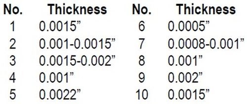
"All of these meet quality specifications for thickness, yet quality was lacking; the bumpers were rusty, because the deposit was poorly adherent.
"It is assumed that the bumper bars were inspected and showed no indications that the plate would peel or blister and thus allow corrosion to start. Under conditions that cause corrosion, the plate is being pushed up by the rust that forms.
"The fact that such a large percentage of non-adherent plating gets out, indicates that there is a need for development of a practical method for testing the adherence of the deposit. Until such a method is developed, it might be wise to develop specifications for processing work through the cleaning and plating to assure a minimum of failures from this cause.
"I do not mean to convey the thought that such failures apply only to the automotive industry. It occurs on other manufactured goods, even at times on silver plated tableware.
"I once wrote an article on 'Plating to Specifications' and in it suggested what I thought was a good test for adherence. I also thought that the idea was original with me; since then, I have learned that I was wrong in both assumptions. The idea was to solder a lug on the surface to be tested for adherence, then pull it off. I even rigged up a gadget so I could measure the pounds' pull required either to fracture the solder or peel the deposit from the base. When I first sought to get advice from authoritative sources, I was told the heat required to solder the lug to the plated surface would affect adversely the adherence of the deposit. Therefore, the test would be without significance. I tried to discover if the heating did affect adversely the adherence of the deposit by heating test pieces to temperatures higher than required to do soft soldering. In some instances, I heated the test pieces to a red heat, and found that after this heating, the adherence was as good as before, so I concluded that the test was satisfactory and proceeded to use it. But, the results were not satisfactory, because sometimes I was sure the test should show peeling, but it didn't."
William Blum,31 of the Bureau of Standards, has the following to say:
"No exhaustive or very conclusive measurements have been published upon the adhesion of plated coatings. One reason for this dearth of literature is the difficulty of developing reliable quantitative tests for adhesion of thin layers. The only methods that are even promising are those which depend upon deformation of the base metal and observation of the behavior of the coating. In the absence of quantitative tests of adhesion, most of the published statements on this subject, including those in this paper, are opinions that are based either on general principles or on qualitative observations and commercial experience."
The galvanizing industry also is confronted with this problem of adhesion and methods for measurement. Methods suitable in this field might be used in electroplating. The zinc people as a group have given more attention to standardizing tests than the electroplaters.
B.P. Finkbone65 makes some remarks along this line:
"Differing from other physical properties, the adherence of the coating cannot be determined in absolute units. Efforts to measure progress toward more adherent coatings have, therefore, resulted in many different ways of testing and a variety of methods for describing the results.
"In the past, specifications have been written which have endeavored to cover this question of adherence. In ASTM Designation A93-27, paragraph 5(b) covers coating tests as follows."
The specifications are then listed, and the following remarks are made concerning them:
"Although these tests may serve the purpose of detecting obviously inferior coatings, there is no doubt that their severity in no way approaches the severity of commercial forming and drawing operations which are met in present day use of high speed presses and forming machinery. A further consideration of these methods indicates that the personal element enters into the forming and inspection of the bends, since a wide variation is likely to occur in the way in which the bends are made."
In discussing the paper by Finkbone, W.H. Finkeldey makes the following remarks:
"I am very glad to hear Mr. Finkbone bring out the point that some type of standard test procedure to determine the adherence of zinc coatings is necessary. I don't know of any single thing, in my limited experience with zinc coating over a few years, that would more quickly allow both the people using zinc coatings and those who are working with them in research laboratories to try to do something to improve them or what would allow them to more quickly arrive at a good result. I know of nothing better for that than a good standardized test for adherence of zinc coatings.
"I think it is time somebody developed a test that we can all use pretty much as the Erichsen test is used today. The methods used today are not suitable for zinc. When that day comes, we will all be helped a great deal in our study of galvanized coatings."
As an introduction to the detailed discussion of each of the various methods for measuring adhesion it is well to make a list of the methods and some brief remarks concerning them. This is well presented in a communication from F.C. Mesle and follows:
"In most cases if the bond between the base and the electrodeposited metal is not good, the plating job is a failure; hence the importance of adequate test methods.
"The problem is to find a test method that will indicate the bond strength between the base and the electrodeposited metal.
"Electrodeposits may show no bond weakness during the normal finishing operations such as buffing, burnishing or brushing, yet will blister or peel from the base after the article has been in use a short time, or has been exposed to corroding conditions. On many articles, the only test for good bond that is applied is the finishing operations; this test is not adequate.
"There are tests that can be made, such as deformation tests, like flexing or bending to the breaking point, using an Erichsen machine, Brinell testing machine or similar methods; all such tests destroy the piece tested.
"There are more positive tests such as the hammer and chisel tests or modifications thereof, and tests with the alligator wrench, that can be used on heavy deposits (0.01 in. and up). Test methods such as apply positive pressure to separate the deposited metal from the base in most cases will also destroy the piece tested, but such methods are useful for checking which plating procedure will give best bond for a given metal, and for studying the various factors that affect the bond strength. The Ollard methods and the micro-adhesion method (which is a modification of the Ollard method) are the only methods so far as I know that express the bond strength in terms of psi.
"In the case of the Ollard method a specially prepared piece of metal is plated, then tested for adhesion. In using the micro-adhesion method tests can be made on a section taken from a production run item.
"Another method is the can opener type of test. This method also requires the plating of a prepared piece of base metal so that one end has no bond to the base. This loose end is inserted in and rolled up on the 'can opener' so that pressure can be applied to separate the deposited metal from the base. This method can be used to determine relative bond strength for various plating procedures, but it is difficult to express this in terms of psi. It can be used on samples from production run items; but it would destroy the finish, making refinishing and re-plating necessary.
"The black light test and modifications of it are used to test bond, but only indicate no bond at open edges where oil can penetrate between the deposited metal and the base. The deposited metal may blister badly but unless there is a break in the deposited metal so that the oil can penetrate between the deposited metal and the base, there is no bad bond indication by this test.
"X-ray is used in a test method for bond but I doubt if it could determine bond strength. It does no doubt show areas where there is no bond.
"The hammer and chisel test method and modifications of it can be used on heavy deposits (0.1" and up). There are three ways this method can be used to check the bond on items like bearings where only one side is plated:
A. Plate the bearing so that the silver plates up above the edge of the base to allow the application of the hammer and chisel test.
B. Allow extra stock in the steel shell so that when the edge is distorted by the chisel test there is still enough stock to finish to required dimensions after distorted area is removed.
C. Where A or B cannot be used, apply the chisel test on a definite percentage of each lot plated and take the scrap penalty.
"Heating after plating is sometimes suggested as a test for bond strength but it is not satisfactory because there are conditions where heating will cause blistering of the deposit. This blistering occurs because moisture has been sealed in by plating over moist dirt or rust or deep pits in the base. When heat is applied the plate is 'blown up.' Extremely poor bond will, under some conditions, cause blistering on heating. In general, heating after plating improves the bond strength of most deposited metals where diffusion occurs, should the bond be weak as plated.
"Experiments have been made by using what is called a supersonic reflectoscope to check the bond of electrodeposits. So far as I know, results have not been very promising. In this test, supersonic vibrations are reflected from a transmitter through the metal under observation, and indicate any discontinuities in or between any of the layers of metal under test but does not indicate bond strength. A weak bond may not show discontinuities but if the bond blistered slightly so as to cause a void between the base and the deposit this would be detected by the supersonic reflectoscope."
Qualitative and semi-quantitative methods
Bending and twisting tests
The first recorded tests for adhesion so far located were described by C.F. Burgess in an article1 published in 1905 on the properties of zinc coatings. The following is quoted from this paper:
"The toughness and strength of the coatings were tested by passing various samples between iron rollers. In some cases, the coatings were so brittle as to be cracked off in scales by this treatment, and in other cases the zinc seemed to be pressed into the iron, and to preserve a perfectly continuous coating. By bending such samples at a sharp angle after having been compressed by the rollers, the coatings could in most cases be peeled off. Such coatings were then examined for brittleness, ductility and porosity.
"Another test consisted in determining the degree to which galvanized iron could be bent before developing cracks in the zinc. This was done by placing a strip of the iron in a device especially constructed for the purpose by means of which the amount of deflection that is required to produce cracks in the coating can be measured, the cracks being detected by means of a microscope."
The next mention (so far located) of tests for adhesion is in an article3 published in 1911 by Andrew McWilliam and W.R. Barclay on the adhesion of electrodeposited silver on German silver. The research was instituted because of the return of several silver-plated articles from various sources. It appears that the tests previously relied upon were the regular finishing and burnishing processes of production. After some preliminary work, the simple bending test was adopted as indicated in the following quotation:
"With these points in view, several preliminary tests were made with the apparatus available, and finally it was decided to adopt the test which had first appealed to the authors, namely, a simple cold bending test. One part of the sample is gripped in a vice and the free part is bent to and fro until it breaks off. It is advisable that the angle of the bend should be about a right angle in order to ensure that the deposit and the basis metal get sufficient movement relative to one another. It will be evident that this test is an extremely severe one, and the silver must be parted from its base, for the silver on the outside of the bend must move a greater distance than the base metal, and on the inside of the return bend a less distance."
It is interesting to note that in the above quotation it is recognized that a definite procedure for the bend test is desirable.
In 1919 an article8 appeared by W.A. MacFadyen. The objective was to find a suitable method for obtaining thick and adherent deposits of iron on steel in order to build up worn steel parts. The bending test previously described was further modified such that the plated strip was bent backward and forward through an angle of 180°. In addition to the bend test, four new tests were introduced. These are given in the following quotation from the article:
"In the concentration experiments the adhesion of the deposits was tested by gripping the steel strip with its deposit in a vice, and bending it backwards and forwards through an angle of 180° until the strip broke. The quality of adhesion was then judged, as in the best cases the deposit broke off flush with the steel basis, whilst in the worse it split off to a greater or less extent before the steel snapped.
- Squeezing test: The tube was squeezed in a vice until the shorter diameter was about half the original diameter, sometimes until the tube was squeezed flat. This was found to be very stringent, nearly all the deposits beginning to flake off where gripped. The results depend partly on the original thickness of the steel tubing, since a thin walled tube can be squeezed much more easily than a thick one, and the results are consequently better in the former case.
- Impact test: The tube was struck repeated heavy glancing blows with a hammer having a one-pound head. This seems to be a good test, the deposits varying a good deal in results.
- Sawing test: The tube was held in a vice, and a piece was then sawn off the end with a hacksaw. The quality of adhesion appeared to be inversely proportional to the thickness of the deposit, for thicknesses up to about 0.02 in., but really thick deposits, say 0.15 in., always stood the test well.
- Grinding test: The deposit was ground through by a dry emery wheel 6½ in. in diameter, rotating at a speed of 1400 rpm. Most deposits stood this test very well, though the top and bottom of the cathodes often stood it badly, this often being undoubtedly due to handling the cathode with the fingers after coppering."
In this country, J.D. Alley was also working upon the electrodeposition of iron for building up worn parts. In his discussion of a paper9 by E.A. Vuilleumier on nickel deposition he briefly describes three methods he used to test adhesion. One is the familiar bend test, but the other two appear to be new up to this time; one is somewhat similar to present day quantitative tests. His statements follow:
"In the second test, we took a piece of cold rolled steel about an in. in thickness and had a hole drilled in it. We plated on our rods and ground them accurately to size; the hole in the cold rolled steel block was made a half mil smaller than the rods, and we pressed the rods through this hole and back, and there were no signs of stripping of the plated material from the parent metal.
"In the third test, we heated the iron after the material had been plated on, and forged it. We could not get it to crack or break off, and in the microphotographs of it that were taken, we could not see a dividing line between the plated-on material and the original cold rolled steel, except in the difference in the appearance of the two metals."
The first indication of an attempt to standardize adhesion tests is contained in the abstract18 of a report by H.A. Stacey in 1926. The abstract follows:
"In an attempt to draw up a specification for galvanized sheet steel, the sub-committee of the Federal Specifications Board made a series of tests to obtain reliable information on the following points: (1) the minimum mandrel thickness, expressed in terms of the thickness of the sheet tested, over which sheets of different weights of coating can be bent 130° without serious damage to the coating; (2) the minimum radius of curvature on the inside of the angle of 90° bends in such material; (3) the effect of double seaming on the coating; (4) uniformity in the thickness of coating over a sheet, particularly as related to the results of bend tests.
"The material and test procedures are described with diagrams and are discussed. Stripping and bending test data for a large number of 16- and 22-gauge sheets of different coatings are given with summary diagrams, also close-ups of sheets after bending, and a proposed clause to cover bend properties."
In an article22 by G.B. Brook and G.H. Stott on testing of electrodeposits on aluminum the authors propose a real attempt at standardization of the bend test. It should possibly be designated as the twist variation of the bend test. This article together with the discussions contain so much valuable material that large sections of it are quoted here:
"Simple workshop tests as a rule leave much to be desired; such a 'bending test' is adopted by Work; others, in which the material is sheared in an endeavor to promote the fracture of the deposit from the underlying metal, and abrasion tests, are all, by their very nature, unsatisfactory, in that they are not carried out under controlled conditions, and hence are not truly comparable. The authors sought to evolve a test in which each part was standardized - namely, the length and width of the strip, the rate at which the bending was carried out, absence of irregularity in the bending movement - and, at the same time, sufficiently drastic to disclose the weakness or poor adhesion of the deposit. One factor, which could not be controlled, has to be admitted, although this was not a serious one in the particular specimens on which the test was done: manifestly, for the same diameter rod around which the test-piece was twisted, the same gauge of sheet should be used for the test pieces. This certainly should apply to substantially thicker material than that which was represented by these particular samples, but we do not think that such variations in thickness as obtained would materially affect the results.
"The test consists in twisting at a uniform rate of standard strip 8×½ in. around a ½-in. bar, the bar (B) being held in the chuck of a precision lathe rotating at 20 rpm. The test strip is inserted in the slot (A) [Fig. 1], which was so cut as to allow the strip to emerge at an angle of 60°, the edge of the slot being rounded off to prevent fracture of the test strip; the other end of the strip (C) is held firmly in pliers, and the lathe started, the resulting strip being bent into the form shown in [Fig. 2].
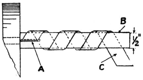
Figure 1 – Mandrel for twisting test (electrodeposits on aluminum).
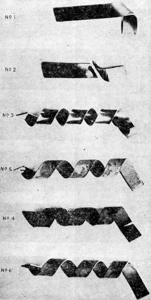
Figure 2 – Plated strips bent with mandrel shown in Fig. 1.
"On the whole, the test worked excellently, but should it be adopted as a standard method further investigation is required, and standards set up for pure aluminum and alloys of different kinds.
"It would also be desirable to bring all materials, before testing, to one temper, always provided the temperature employed is not such as would tend to promote blistering or peeling of the deposit."
The published discussion of this paper contains several highly pertinent and valuable remarks some of which are quoted below:
"Prof. D. Hanson, Prof, of Metallurgy, The University, Birmingham, D.Sc. (Vice-President): The twisting test is a very severe test; six out of twelve samples withstood it successfully. Whether a coating would stand a test of this kind depends partly on the amount of internal stress.
"Frank Mason, Stainless Plating, Ltd., Sheffield: While the methods formulated and explained in this paper will prove an efficient test for the adhesion and porosity of electrodeposits upon most metals, it is problematical whether this all-important and distinctly characteristic tendency of the metal to strip or lift in blisters when deposited on aluminum will be revealed by the procedure adopted. I trust that further investigations will be carried out in this very extensive field.
"Mr. H. Sutton, Chief Metallurgist, Royal Aircraft Establishment, South Farnsborough; and Mr. A. J. Sidery, Metallurgist, Royal Aircraft Establishment, South Farnsborough: Turning to the authors' test for adhesion of the deposits, we observe that the thickness of strip was not standardized. We would suggest that the radius of bending should be expressed as a multiple of the thickness of the sheet, thus rendering the test applicable to any thickness of sheet.
"Dr. Harold K. Work, Research Bureau, Aluminum Co. of America, Buffalo, NY: The authors have undertaken a most difficult problem - namely, to measure accurately the adhesion of electrodeposits to a basis metal. They state that simple workshop tests such as bending (which I used in an investigation to which they referred) leave much to be desired. I agree with the authors in this. However, the substitution of a more standardized and more complicated test would only be justified if the simple bending test did not accurately reproduce its results, or if the standardized test were more accurately a measure of adhesion. It has been my experience that such simple tests can be reproduced, provided, that certain conditions are kept constant. These are the thickness, temper, and other physical properties of the metal plated upon, and the thickness and physical properties of the coating - the same properties which must be constant in the twisting test.
"As to keeping the temper of the basis metal constant, that is not advisable, because the quality of the plate varies with the temper of the metal plated on. This makes it impossible to bring the metal to one temper before plating. It is equally useless to bring the metal to one temper after plating as the authors suggest, because this process would affect the adhesion.
"The only way in which the twisting test could be made valuable quantitatively would be to prepare a test on a given coating for every temper of every alloy that is commercially used. This is impracticable, considering the number of alloys that are now on the market. Neither does this procedure apply to castings. Even if these careful tests were made they would be useless in measuring true adhesion unless the physical properties of the plate were kept constant.
"It is my opinion that the most serious objection to the simple bending test applies equally to the standardized twisting test; neither actually measures the true adhesion of the coating. The experiments of the authors bear this out. It will be noted that their sample B, which is copper coated, exhibits 'good adhesion' while sample A fails, due to the application of a nickel layer over the copper. Undoubtedly the true adhesion was poor in both instances, and the added nickel merely set up greater stresses which effected the peeling. These same stresses were undoubtedly responsible for the fracture of the basis metal which the authors reported. The strong nickel layer being on the outside of the twisted specimen would tend to bear the main burden of the tensile stresses. When the nickel due to its low workability cracked under the stresses, it left areas of unprotected aluminum under these cracks with other areas of aluminum between reinforced by a nickel sheath. Naturally, with this localization of the stresses, the aluminum gave way.
"The Authors (in reply to correspondence): One of the authors in his reply at the meeting, dealt with the suggestion made by Mr. Mason as to a burnishing test furnishing a means of discovering an insecure deposit. From a long experience, one can answer the suggestion both in the affirmative and the negative, but as in the majority of cases the basis metal is either etched deeply or actually rendered extremely rough by sand-blasting, the burnishing test suggested by Mr. Mason would, in this case, not be possible.
"We recognize the fact that if the bending test is to be standardized, consideration of the thickness of the material would have to be taken into account, and we are obliged for the valuable suggestion put forward by Messrs. Sutton and Sidery - viz. to express the radius of bending as a multiple of the thickness of the sheet. We would also point out that the thickness of the deposited metal film was actually determined chemically, so that the point raised by Messrs. Sutton and Sidery is satisfied.
"We much appreciate Dr. Work's contribution. The statement in his first paragraph appears to be somewhat contradictory - he first agrees that simple workshop tests leave much to be desired, and then claims that such workshop tests can be reproduced. It is actually the variation which is always present in the so-called workshop test that led us to call attention to the need of standardization - e.g., it is conceivable that in the simplest of bending tests the radius and speed with which the bend is made may vary where, as is often the case, the test strip is bent between the noses of two pliers. Whilst recognizing the important points raised by Dr. Work regarding thickness, temper, and the physical properties of the deposit, all of which we dealt with in our paper, it has to be admitted that such variables demand equal consideration in a simple and uncontrolled bending test.
"In putting forward this test, we recognized that it was not intended to be the final form, but rather a guide to those who had made tests their special study.
"We recognized and admitted in the paper the difficulty with regard to so treating the test specimens as to bring them to the same temper; not particularly from the point of view of the test itself, but recognizing the fact that the articles themselves, of which the test-piece only formed a part, could not be so annealed. It would be manifestly unfair to carry out a test under conditions other than those which the article actually in use would be called upon to sustain."
In 1932, A.W. Hothersall37 made an exhaustive study of adhesion measurements. He describes improvements in the peeling tests frequently used, and his variant of the bend test is very interesting. His remarks on these tests follow. His study of other tests will be presented later.
"Qualitative tests: A nickel deposit 0.02 in. in thickness was formed on both sides of a suitably prepared brass sheet about 2 in. square, and in most cases not less than about 0.03 in. in thickness. The deposit was then tested in the manner illustrated in [Fig. 3] and comprising the following stages:
- The edges of the composite plate were sawn off so as to expose the brass and the cut edges filed smooth.
- Attempts were made to detach the deposit from the brass by means of a hammer and chisel; if possible, the deposit was turned outwards and flattened in the form of a tongue.
- The tongue of deposit was gripped with pliers and pulled away from or twisted off the brass.
- In cases where the deposit could not be readily separated from the brass by means of a chisel, a saw cut was formed in the specimen, which was then gripped in a vice just below the cut and bent over until fracture occurred, when the degree of adhesion could be approximately gauged from the appearance of the fracture - e.g.,
- With coatings not firmly adherent, some degree of separation of the deposit from the brass could be seen at the site of the fracture (in which case further chiseling tests were carried out), or
- With very strongly adherent coatings there was no sign of separation of the deposit from the brass."
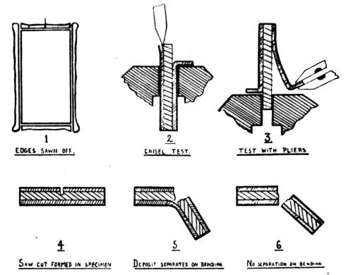
Figure 3 – Qualitative adhesion tests.
He also makes an attempt to classify degrees of adhesion based upon qualitative measurements as follows:
"Slightly adherent: Only a very slight degree of resistance was experienced in detaching the deposit which, when separated as shown at (2) of [Fig. 3], could be pulled off with the fingers.
"Moderately adherent: Some degree if resistance was experienced in attempting to pull the deposit off the brass, and the pliers had to be firmly gripped. Detachment was, however, effected fairly readily by means of a direct pull.
"Fairly strongly adherent: Vigorous direct pulling with the pliers only succeeded in detaching a small portion of the deposit, but if the deposit could be successfully gripped with the pliers it could be detached by twisting after the manner in which a sardine can is opened. Detachment of the deposit in one piece could, however, be effected by means of the chisel.
"Strongly adherent: Some separation with the chisel was possible, but only small pieces could be detached as such force had to be used that the chisel cut through either deposit or basis metal.
"Very strongly adherent: No separation of the deposit from the basis metal could be effected by any of the methods referred to above."
As pointed out before, the galvanizing profession has made a greater effort to standardize and to consider the bending test in a more quantitative manner than the electroplating profession. This is illustrated in an article by H. Bablick.27 An attempt is made to consider somewhat quantitatively such factors as bending radius, thickness of the base metal and of the deposit. He states:
"In [Fig. 4] are shown the conditions for a hot-galvanized coating when it is bent. There is a great difference in lengthening of the three layers of a hot-galvanized coating. Especially interesting is the lengthening of the outer pure zinc layer, in view of the neutral zone of the iron base. From the calculation given, the lengthening of the pure zinc layer is dependent on the bending radius and on the thickness of the sheet. As the calculation shows that the lengthening E = h/2R, it follows that the lengthening becomes greater as the sheet is thicker and the bending smaller."
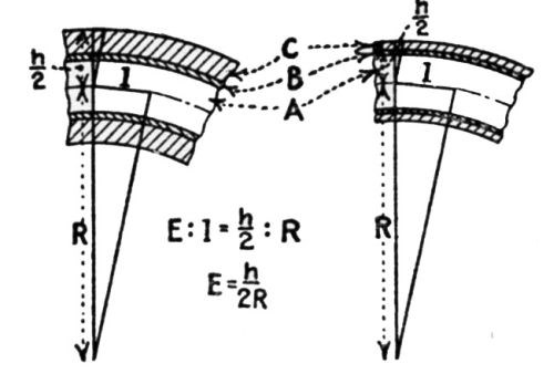
Figure 4 - Elements in bending hot galvanized sheets. A is the iron base, B the iron-zinc alloy layer, C the pure zinc, E the extent of lengthening, R the bending radius, h the total thickness of the galvanized sheet.
There is one type of test, several variations of which are being used, that H. Bablick does not consider a test for adhesion. His statement on this point follows and also an illustration is included:
"Of course, we can imagine that the danger of the peeling off of the coating increases with the increasing of the lengthening. It must also be stated here that numerous experiments have repeatedly established the fact that, by any lengthening of a galvanized sheet, the coating peels off only when the lengthening of iron base differs from that of the coating.
"If the iron base and zinc coating are lengthened to an equal extent, there is no likelihood of the zinc coating breaking before the iron base. A lengthening after the manner of [Fig. 5] will, therefore, never result in coatings peeling off. In the case of bending, the lengthening of the iron base differs from that of the zinc coating, so that the two layers are stretched side by side and concurrently to different lengthenings. The result is that they are forced apart, as shown in [Fig. 6].
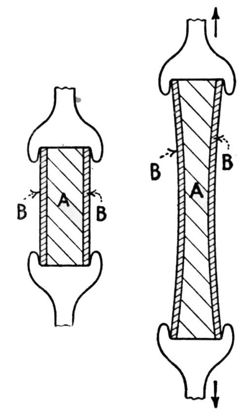
Figure 5 - Straight lengthening of a coated sheet changes condition from that at left to that at right, without peeling of the coating. A is the iron or steel base, B the layer of zinc.
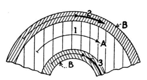
Figure 6 - Unequal lengthening of the base and coating caused by bending leads to peeling. A is the base metal, B the zinc coating, 1 the lengthening of the neutral zone, 2 and 3 the differing lengthenings of the two zinc layers.
"This explains the well-known fact that galvanized coatings when heated peel off. We must remember that there is a great difference between the expansion qualities of iron and zinc. Under ordinary conditions the expanding of zinc is nearly twice that of iron. Thus, there is a difference in the lengthening of the two main layers with the result - a separation and, further, the peeling off of the zinc coating."
An attempt at a standardized procedure, adopted by some of the most responsible groups in the country, is briefly described and well-illustrated in this same article by Bablick (Figs. 7 and 8).
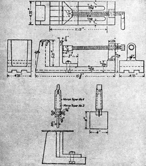
Figure 7 - Laboratory apparatus to test bending quality used by Washington Navy Yard.
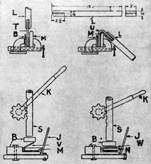
Figure 8 - Laboratory apparatus to test bending quality used by New York Navy Yard, National Bureau of Standards and New Jersey Zinc Company. T is the test piece ready for bending, U same after bending to 135°, V same ready for compression over 2-in. mandrel M, W same ready for 1.75-in. mandrel N, L lever for first bend, K operating lever for spindle S, J lever to hold mandrel up to its work, B blocks of wood or fiber.
Another type of bending machine is recommended by R.L. Templin70 (Chief Engineer of Tests, Aluminum Co. of America) in which some attempt is made at standardization. Samples of a definite width may be used, the angle could be made 90° or 180°, and the bend could be made over mandrels of various diameters. The rate of bending could also be standardized. The radius of bending could be made to have a definite relation to the thickness of the sample. The results could be expressed in different terms as desired. A picture of this device is given in Fig. 9.
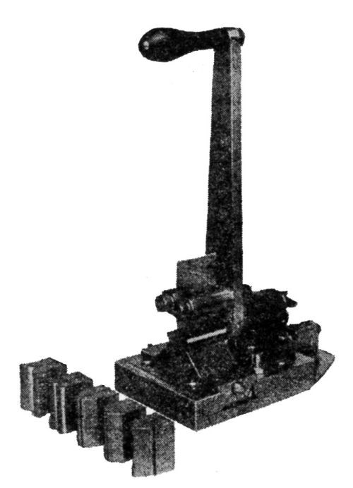
Figure 9 - Repeated bend test machine for thin sheet metal.
One of the most recent bend testing machines is that described by R.E. Wheeler89 in 1938. It was designed for testing organic finishes but might be used equally well for electrodeposits. The following is a discussion of this machine and its operation in Wheeler's own words:
"Testing an organic finish for adhesion by bending over mandrels of various diameters and noting the smallest diameter which ruptures the film has been used as a means of comparing finishes for many years. This is a rather tedious procedure since it requires several different bending operations. Ordinarily, this means that several panels must be prepared or that one panel must be completely ruined to perform the test and additional panels must be made if further tests are to be run. A bend tester on which a panel can be passed over several different radii at the same time and yet preserve the panel for further tests is illustrated in [Figs. 10, 11 and 12].
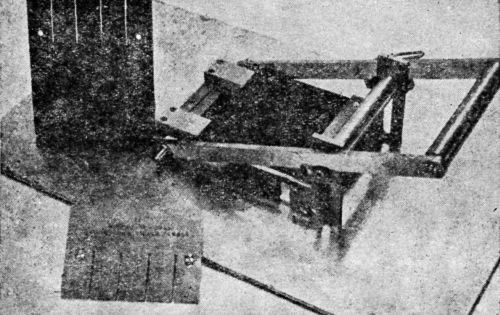
Figure 10 - Bend test machine on which panel can be passed over several different radii simultaneously. Note roller, template for cutting panels, and cut panels.
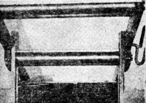
Figure 11 - Front view of bending blocks ground to various radii.
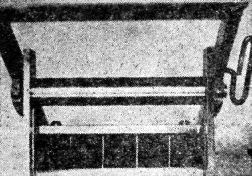
Figure 12 - Panel in bend test machine following bend testing operation.
"[Figure 10] shows a general view of the bend tester showing the roller which gives a true rolling action to the bend and also the template for cutting the panels and a panel as cut and finished. The template has slots cut in it approximately 1 in. apart to correspond to the bending blocks shown in [Fig. 11]. There are also two holes drilled in each side of the plate so that the panels can be bolted together while they are being sawed. The template is of necessity case hardened. The panels used measure 4¾×6 in.
"When it is desired to prepare panels for testing, thin sheet steel is cut to the required size. Eight or ten panels are then clamped to the template and the two holes are drilled. A nut and bolt is then inserted in each hole to hold the panels together and a clamp is placed on each side of the slot to be sawed. The entire assembly is clamped in a vise and the four slots sawed out. The panel is coated with the material it is desired to test and is then fastened to the tester by means of a bar. Holes are drilled in this bar which correspond to the holes in the test panel and also the bending blocks. Two bolts which pass through the bar and the panel and which thread into the bending blocks are used to hold the panel in position while a test is being made.
"[Figure 11] shows a front view of the bending blocks which are ground to 90° and the following radii: ½ in., ¼ in., 1/8 in., 1/16 in. After inserting the panel as described above, the key which holds the handle in the up position is removed and the handle is then pressed downward. This action forces the roller to roll over the faces of the bending blocks with enough clearance being allowed for the panel.
"A sample panel after the bending operations is shown in [Fig. 12]. The panel can be removed for inspection and the rupturing radius recorded. The bent end can then be cut off or the panel used as it is for additional tests. In constructing this type of tester, one must be sure that the bars which support the roller and handle are long enough so that the roller will describe nearly a straight arc across the faces of the bending blocks on the downward stroke."
During recent years there has been much greater attention given to adhesion. Several times, hammering has been mentioned as an extra severe test. In it the sample is first bent completely back upon itself, and then the bend is hammered down. In discussing the article by F.C. Mathers and L.L. Gilbertson,80 G.B. Hogaboom, Jr. remarks:
"There is no good method for testing the adherence of deposits on experimental steel plates. The simplest test I have found is to bend the plate at 180° and hammer it flat. If the deposit stands that hammering at the point of curvature, you may be relatively certain that it is adherent."
Bending and twisting tests of some nature are by far the most commonly used for testing adhesion, especially for thin deposits, but to a considerable degree even for thick deposits such as used on bearings. Wherever the nature of the tests is mentioned in the literature, some kind of a bend test is almost universally included. It is equally true that a bending or twisting test is included by those who have sent in private communications referred to in a later article.
Burnishing, buffing and abrasion tests
The literature does not contain much information on this type of test. The first mention so far discovered is by C.F. Burgess1 in 1905. He states:
"The method employed for testing the resistance to abrasion consisted in placing samples of galvanizing in a porcelain-lined tumbling barrel, together with quartz sand. After the barrel had been turning at a slow rate for a number of days, weight determination showed the amount of zinc which was removed per unit area of surface."
The method is again mentioned in an article3 by Andrew McWilliam and W.R. Barclay in 1911. They state:
"In order to correct a misapprehension which might arise, it may be necessary to point out that no attempt is here made to discuss the ordinary causes of the 'stripping' or 'peeling' or 'blistering' of electrodeposited silver from the base metal during processes of manufacture - because articles so treated rarely pass from the hands of reputable manufacturers, the faults being revealed during the subsequent finishing and burnishing process, it being well known that if the slightest trace of grease or oxide remain on the surface of the base metal, the electrodeposited silver will blister under the pressure of the steel burnishing tools used in finishing."
From these remarks and others, the inference is clear that burnishing operations during the regular manufacturing process had been generally accepted by the silver platers up to that time as a satisfactory test for adhesion. From more recent remarks, it is evident that it is still generally considered by them as satisfactory. Private correspondence and interviews during the progress of this research show that some variant of this type of method is extensively used by many platers at the present time.
S. Wernick82 states:
"Burnishing test: It shall be possible to burnish the deposit with a blunt instrument and this operation shall in no way result in the flaking or blistering of the deposit."
Again, in a later article,109 Wernick states:
"Inadequate adhesion to the basis metal may not be immediately apparent, but it can be readily detected by local burnishing of the plated surface. The friction engendered soon results in the development of a gap between the deposit and basis metal. This method of detecting non-adhesion constitutes a useful workshop test of this property. Local non-adhesion quite commonly manifests itself by the appearance of circular mounds, termed blisters by platers."
C.F. Bonilla72 published an article on heavy nickel and chromium deposits, in which he makes the statement:
"I term inadequate adhesion any peeling on vigorous buffing or on rubbing strongly on the plated surface with a hard blunt edge such as worn screw-driver."
B. Egeberg and N.E. Promisel77 state:
"Burnishing: If, at twenty-five pounds pressure, the burnishing tool produces no lifting of the plate (blisters), the adhesion is generally satisfactory."
A. Hirsch82 makes the statement:
"A barrel burnisher (16×30 in. diameter, 27 rpm) containing 900 lb. of 7/32-in. steel diagonals was used to test adhesion of the nickel deposit. In this test deposits of poor adhesion would 'shell' off the base metal immediately when the burnishing started, while good deposits would burnish indefinitely without 'shelling' of the deposit."
Donald Wood, in an article90 on nickel plating on stainless steel, calls attention to the use of a test "equivalent to ball burnishing."
Ball burnishing is frequently used for polishing, but at the same time it tests adhesion also.
E.G. West97 has the following to say:
"Electrodeposits are polished by ball burnishing to a higher degree of lustre than is possible by mopping ('buffing" in U.S.). Further, the cold working by the balls results in slight hardening and also acts as a ready test for adhesion. This method is particularly useful for precious metal deposits and for the softer coatings, although matte chromium deposits can also be treated."
P.J. LoPresti127 makes the following remarks:
"Samples were also barrel-burnished for one hour in a small wooden hexagonal barrel with a load of 1/8-in. steel balls weighing 30 lb. using a standard soap as lubricant. Here, again, the silver plate over a phosphate coat was as adherent as the standard silver plate."
In private correspondence and interviews it is evident that this method is in fairly general use today. There is the possibility that a machine might be constructed in which are standardized various factors such as pressure, surface area of contact, area burnished, nature of burnishing tool, speed of operation, etc., and which could give rough quantitative information on adhesion. The method would be usable for only relatively thin deposits.
Impact or hammering tests
Impact or hammering tests for adhesion were among the first to be used. The first suggestion that such a test be used, was made by C.H. Proctor7 in 1916. He states:
"The zinc deposit apparently becomes impregnated or alloyed with the steel and withstands the severest bending tests and can be hammered completely into the steel itself. Experiments made with temperatures up to 750 to 800°F. have apparently no effect upon the deposit."
The same year M.W. Baldwin6 in a paper on plating of aluminum remarked as follows:
"It is then nickel plated in the usual manner. The plating adheres perfectly - when hammered or bent, the deposit will not crack and the metal can be heated to the melting point of aluminum without separation of the nickel."
W.A. MacFadyen has an article8 in 1920 dealing with thick electrodeposits of iron. Several adhesion tests were used, one of which is called the "impact test." Concerning this he states:
"The tube was struck repeated heavy glancing blows with a hammer having a one-pound head. This seems to be a good test, the deposits varying a good deal in results."
J.D. Alley9 described several tests he had used to evaluate the adhesion of thick deposits of iron, among them a forging test:
"In the third test, we heated the iron after the material had been plated on, and forged it. We could not get it to crack or break off, and in the microphotographs of it that were taken, we could not see a dividing line between the plated-on material and the original cold rolled steel, except the difference in the appearance of the two metals."
R.J. Piersol47 describes an impact testing machine which he developed:
"For conditions where thick plates of chromium are deposited on a non-flexible foundation metal, the writer has developed the impact method of testing for adhesion. As shown in [Fig. 13], the plated specimen A is held in place against the impact block B. The impact blow is struck by the impact hammer C which drops by pendulum motion with the arm pivoting at D, the hammer being raised by hand to a horizontal position and then permitted to drop by gravity. The number of blows the plate will stand without being knocked off is an index of its adhesive strength."
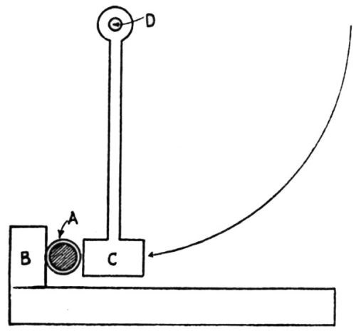
Figure 13 - Impact method of testing adhesion of electrodeposits.
Another type of impact test, variations of which are in fairly general use, is described by S.G. Clarke in his paper64 on black lead peroxide coatings:
"The deposits were all hard and relatively brittle, but the adhesion varied according to the smoothness of the basis metal. The following tests were carried out on deposits generally of about 0.0005 to 0.0010 in. in thickness. Fairly hard scraping with a steel blade or scribe was required to score away the deposit, but when struck, e.g., with an edge of a metal rod, fragments of the coating chipped off. For the purpose of comparing adhesion of different surfaces, blocks carrying the coating were indented by a loaded 5-mm ball, and the degree of flaking around indentations of similar diameter (about 2.9 mm) was noted. According to this test, the adhesion on bright rolled steel and polished copper was poor or negligible and considerable flaking occurred. The adhesion on shot-blasted mild steel and rolled copper was better, and there was further improvement with the coating on unpolished electrodeposits (0.0005-in. thick) of copper, zinc or cadmium on steel, little or no flaking being found. The results of bending sheet specimens gave indications that whilst little difference could be detected between coatings deposited at temperature up to 60°C, those formed at 100°C were considerably more brittle and less adherent."
A somewhat quantitative use of the impact tester just discussed is described by R.C. Martin:86
"The coated metal panel is inserted in the base of a 32-in. frame. The panel is placed over a series of hollow metal discs with the coated side of the panel placed downward on the disc. A metal disc contact centered with a ball-bearing device is placed on a cross arm. This arm may be dropped from any point along the 32-in. scale. The extent of rupture will evaluate resistance to impact. The weight used and distance dropped determine the factor."
The most recent development of an impact tester is described by A.W. Hothersall and C.J. Leadbeater:130
"The need for a suitable test for adhesion of electroplated coatings has long been recognized. Most methods so far suggested or used can be classed as: (1) methods in which the article is permanently deformed (bending, hammering, cupping, etc.) and (2) methods in which the coating is scraped, pulled or levered from the base. All of these methods are in some respects unsatisfactory. In the present work three types of test were investigated:
- The BNF adhesion test, in which a vibrating ball-ended hammer, actuated by a fluctuating magnetic field, bombards the surface and produces blistering of the coatings if poorly adherent;
- The shot impingement test, in which the surface is bombarded with rounded steel balls;
- The electrolytic test, in which the component under test is made the cathode in a dilute H2SO4 solution.
The two latter tests did not prove satisfactory for general application. Method (1) was found to be useful for testing adhesion of non-adherent or weakly adherent coatings. No blistering was obtained when the value of the adhesion measured by another method was only 0.57 tons/in.2, showing that the method measures only very poor adhesion. Blisters were produced, usually within ten seconds of commencing hammering, in poorly adherent deposits of Cr, Ni, Cu, Cd, Zn, Sn and Cr over Ni. Deposits were tested on Pb, Al, brass, mild steel and hardened steel.
"Thicknesses of plate in which blistering was produced varied from 0.0001 to 0.006 in. A hammer-head diameter of 0.06 in. is most serviceable. The test was applied with practical results to 52 specimens of commercially plated hardware and plumbing fittings. An advantage of the test is that it does not injure the basis metal. Although designed for electroplated coatings, it appears to have possible applications to coatings, both metallic and non-metallic, formed by other methods, e.g., sherardizing and painting."
The BNF adhesion tester, according to W. Canning & Co., Ltd. of Birmingham, England, who manufactures it, has been approved by the British Standards Institute. Since it has created considerable interest also in this country, we reproduce from Canning's Catalogue No. 2581 on the Adhesion Tester [Figs. 14-17]. We also quote from the instructions for the use of this apparatus, which is operated from a 200-230V, single phase, 50 cycle AC supply, as follows:
- The tester can be used in two ways, as illustrated [Figs. 16 and 17]. If the article to be tested is heavy it is better to take the adhesion tester to the article, but for rapid operation on light articles it is better to bolt the tester to a bracket.
- The hammer blows should usually be normal to the surface but sometimes it is useful by tilting the article to combine normal and oblique blows on the same spot.
- The blows of the hammer should be allowed to scatter over a small area, e.g., a circle 1/8 to 3/16 in. in diameter.
- Although it is generally inadvisable to control the action of the hammer, it is possible to regulate the scatter produced by loosely guiding the spring hammer with the fingers. The best effect is obtained by allowing the hammer complete freedom to work at its maximum amplitude which can be judged by the noise produced from the blows.
- The test should be discontinued with the blistering or flaking of the coating, which, with non-adherent coatings, usually occurs within ten seconds.
- The deposit is considered to have passed the test if no blistering or flaking is produced after testing for one minute."
It should be noted that, to quote Canning, this test "only rejects coatings of negligible adhesion." Its operation and limitations would appear to be much like those of the burnishing tests already discussed.
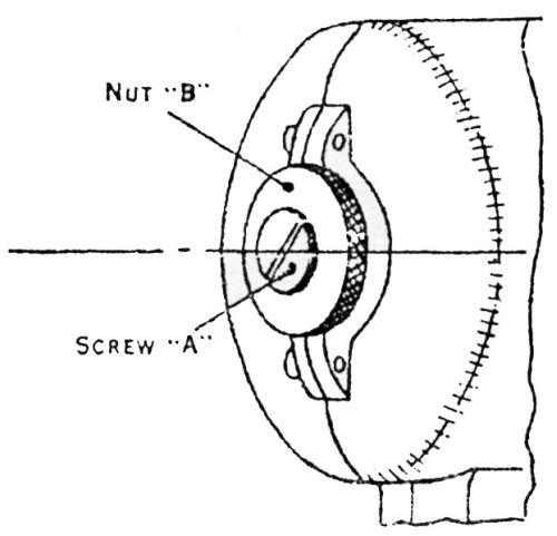
Figure 14 - Vibratory adhesion tester. Pull-off hammer protecting sleeve when using tester.
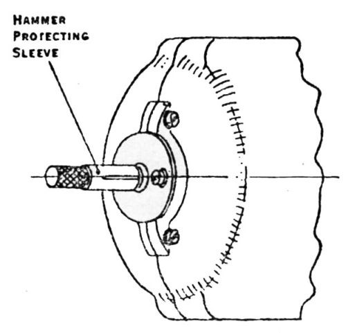
Figure 15 - Vibratory adhesion tester. Adjust Screw A to obtain maximum stroke and lock securely hammer-adjusting nut B. Maximum vibration obtained when article is applied to the tester.
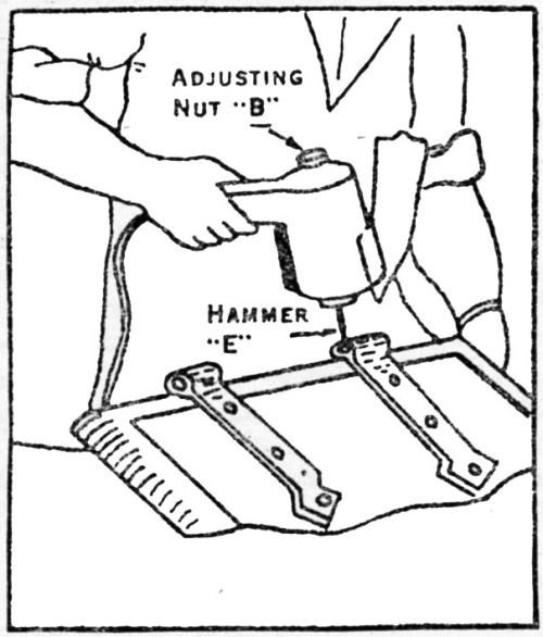
Figure 16 – Vibratory adhesion tester used as portable instrument.
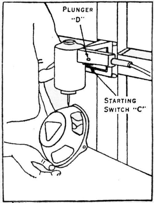
Figure 17 – Vibratory adhesion tester fixed to one type of wall bracket.
Heating test
Heating electrodeposits as a test for adhesion is one of the oldest methods used. It was first mentioned by C.F. Burgess1 in 1905. From that time until within the last few years, it is seldom mentioned, but recently it has received more attention. The comments of Dr. Burgess follow:
"An example of the failure of galvanized coatings is seen on galvanized pipes leading from heating furnaces. The alternate heating and cooling of these pipes frequently causes the zinc to become detached in large scales. To determine whether electrolytic zinc behaves in a similar manner, samples of various kinds of galvanizing were heated and cooled alternately and the effects thus produced observed."
M.W. Baldwin, in his article6 of 1916 on plating aluminum, states:
"The metal can be heated to the melting point of aluminum without separation of the nickel."
R.D. Blue46 (in discussion) remarks that after heating a certain electrodeposit on magnesium:
"The absence of blisters proves the excellent adherence."
In the article63 by B.K. Braund and H. Sutton on "Electrodeposition of Zinc and Cadmium on Aluminum and Aluminum Alloys", the statement is made:
"With the best samples, neither heating on a hot plate for 20 minutes at a temperature below the melting point of zinc, nor heating an edge with a blowpipe flame produced any blistering or detached the zinc deposit."
Donald Wood90 mentions as one of several tests he used for adhesion of nickel on stainless steel "heating to 1300°F."
B.F. Lewis103 states:
"The effect of anodic cleaning upon adhesion of the copper has been most apparent in the increased resistance to blistering at temperatures up to 350°F as well as at the normal temperatures."
In the discussion of an article116 on the adhesion of thick silver plate on steel, U.A. Mullin of the Wright Aeronautical Corporation states:
"To test for adherence, we have a preliminary test which is a heat treatment at 950 to 1,000°F (510 to 540°C). If there are any areas of poor adherence not easily detected, for example, a small blister which does not have a pinhole exit, the heat treatment will increase the size of the blister so that you can see it."
In continuing the discussion of the same paper, R.A. Schaefer stated:
"We do obtain satisfactory adhesion as plated with a nickel strike without any heat treatment. We do, however, heat treat, as Mr. Mullin has already indicated, at 950 to 1,000°F to meet specifications AMS 4815, but that is solely as an inspection tool, to cause those areas which have no bond or poor adhesion to blister."
W.M. Phillips, Head of the Electrochemistry Dept., General Motors Research Laboratories Division, followed with the statement:
"Mr. Mullin suggested just about what we use. We anneal once or twice, and in some cases, we anneal a second time to compensate for the cold working that we get in the machine, which puts a double task on the adherence."
He adds another interesting remark which is worth quoting here:
"We have tried some direct tensile tests but we quickly found that our bonds were stronger than the tensile strength of silver, that is, we could pull the silver apart before we could break the bond."
A slight attempt at making the heating test somewhat quantitative is indicated by W.S. Loose in an article118 on nickel plating magnesium alloys. His statements follow:
"A third method that is much used on other metals such as zinc die castings consists of heating the plated metal in a furnace at 120 to 175°C to find the time required to blister the deposit. It is a question whether this is an adhesion test or a test to determine the amount of gas absorbed in the metal and pores. Nickel plated magnesium alloy die casting will withstand at least 72 hr at 175°C. When a die casting coated with a triple plate consisting of nickel-copper-nickel or nickel-cadmium-nickel is heated in this manner, not more than 1 to 2 hr heating can be applied without blisters developing. In these triple plated samples, the intermediate deposit was buffed to eliminate porosity. This difference may indicate that the absorbed gas escapes through the pores in the deposit in castings that have only the nickel deposit."
The simple heating test as used in the manner described by those mentioned above depends, for its effectiveness, largely upon gas contained in the base metal or at the interface which cannot escape but becomes less soluble or expands thus developing a pressure sufficient to push the deposited metal away from the base. It may result also from the vaporization of liquid or other volatile material entrapped somewhere.
A much more drastic test which not only includes the simple heating but adds another factor of considerable importance is used in many cases. This test involves heating the sample, then suddenly cooling it, or the reverse procedure. If there is an appreciable difference in the coefficients of expansion between the base and the deposited metal a very strong force is developed tending to separate the two.
This type of test was used by F.M. Dorsey.20 He states:
"Nickel deposited by the Madsenell process will adhere under bending stresses until the base metal cracks and can be heated to 1,000°C and plunged into cold water without blistering or otherwise affecting the bond."
W.M. Scott in his article17 on chromium plating states in this connection:
"An unburnt deposit on the same article can never be removed or scaled off. For example, a piece of steel, chromium plated, can be heated to cherry red, then immediately immersed in cold water without any effect upon the deposit."
R. Yates98 applies this as a very severe test. He states:
"As an example of the excellent adhesion between aluminum and nickel that is established through the medium of the process described, it may be stated that aluminum permanent mold castings so treated have been heated to temperatures of some 800° and plunged into a bucket of cold water without in the least disturbing the deposit of metal. This is one of the most brutal tests that could be made for any form of plating and offers testimony for the practical nature of the process. Sole plates of aluminum used on flat irons have been employed for months on end in commercial laundries without showing wear. The sponsors of the Travers Krome-Alume Process claim that repeated heating of nickel plated articles tends to increase rather than decrease the adhesion established. Continuous heating tends to alloy the nickel and the aluminum and rather than a form of abuse, it turns out to be an excellent method of furthering a still greater bond."
In another article128 on the same subject he states:
"In the case of 2S and 3S metal adhesion reaches a point where it is practically impossible to remove the deposit except by rather violent chemical means. Such deposits may be heated in Bunsen flames, bent, ground or flexed to the breaking point without risking the danger of lifting the plating. In every instant, heat increases the adhesion rather than decreases it. In one test, aluminum sole plates for flat irons have been plated, heated to 700° and quenched in buckets of cold water without affecting the adhesion of the deposit."
"Black light" or "fluorescent" test
Another test of a distinctly different nature goes by several names, among them being "black light" and "fluorescent." This test has received considerable attention during recent years, but the literature contains only very little information. It is well described and its value indicated in a part of the discussion110 of the adhesion of silver plate on steel:
"U.A. Mullin: If by chance you have an area of poor adhesion on the edge of a piece where the blister does not form because the pressure is released, the test for lack of adhesion in that location is the so-called black light test. This test consists of machining the part so that you have a clean interface between the silver and the iron. The part is heated in a paraffin base oil, allowed to cool with the oil on it, and then the surface oil is thoroughly removed. You can possibly use a quick solvent dip, but it is better to do it with clean rags so that the solvent will not remove any paraffin oil that might be in a crack or pinhole. After the surface oil has been completely removed, the piece is heated again, and if any paraffin oil has been absorbed in a crack or pinhole the heat will force it out. The area is now examined under ultraviolet light, causing the oil droplets to fluoresce.
"Incidentally, the black light test is used only after removing any excess amount of silver. For example, if you want to plate a band 2 in. (51 mm) wide, and have a good adherence for that entire 2-in. width, you will plate it possibly 1/16 or 1/8 in. wider on each side, and then remove that excess at the edges, because for some reason at the edges you will always get poor adhesion.”
"Colin G. Fink: How would you remove the excess silver - mechanically?”
"U.A. Mullin: Mechanically. To make a black light test effective, there must be a clean interface between the silver and the iron.
"I do not know that any of this is new, but I have come all the way from New Jersey for the express purpose of hearing the discussion on the adherence of silver.”
"F.C. Mesle: With reference to the black light test, all it shows is either adherence or no adherence; there is no indication of the degree of adherence."
Earlier in this same discussion, G.S. Krentel made the following highly intriguing statements:
"This question of the adhesion of silver deposits has passed the stage of testing by means of the hammer and chisel. I am sorry I am not permitted to say much on this point, but it is an accomplished fact that there are far superior ways to check and determine relative degrees of adhesion."
It turns out, however, that the test he was not free to expose was the same black light test described by U.A. Mullin and quoted above.
The Erichsen cup test and variants
A type of test which has been developed rather recently and is used by several companies especially for certain metal deposits, depends upon the deposit and base metal being deformed into a cup or flanged depression by means of some sort of plunger. The size and shape of the depressing mechanism and the machine for operating it, also the depth of the depression, are all factors which vary with different operators. It is frequently referred to as the Erichsen Cup Test.
This was used by W. Blum,15 in testing the adhesion of nickel on iron and steel in 1925. In this connection, he states:
"The adhesion of the nickel plating was measured by observing whether the nickel peeled, when the specimen was tested in an Erichsen penetrating machine, in which a plunger is forced against the sheet till rupture occurs. The test was not very conclusive, as all specimens stood it except those in which the preparatory cleaning was known to be defective or in which a large amount of iron was present in the bath and the deposit."
In a later revision15 of the same article, he made the same statement and added:
"When the initial adhesion was good, no failure was observed in this test, even when the plates were heated to nearly red heat (about 500°C or 932°F) and were then plunged into cold water and again tested. For purposes in which a very high degree of adhesion is required, it is probable that some more severe test must be developed than that here described."
In still another article,31 he makes some pertinent remarks on the whole subject of methods for measuring adhesion and especially on the Erichsen method. His statements follow:
"No exhaustive or very conclusive measurements have been published upon the adhesion of plated coatings. One reason for this dearth of literature is the difficulty of developing reliable quantitative tests for adhesion of thin layers. The only methods that are even promising are those which depend upon deformation of the base metal and observing the behavior of the coating. On sheet metal this deformation may be accomplished by a simple bending test, e.g., in a vise or over a mandrel of specified diameter.
"Another method is to apply the Erichsen extrusion test to the coated sheet and to observe whether the coating has flaked or peeled when the base has failed. A modification of this method has been applied to chromium-plated cast-aluminum alloys in a few unpublished tests made at this Bureau. In these tests indentations were made by the ball of a Brinell testing machine with increasing loads, until it was evident that the chromium coating had detached. The results were roughly reproducible and appeared to have some significance. At best, however, such tests usually show that under given conditions the coating does or does not adhere and yield little or no information regarding the relative adherence."
S. Wernick26 used a cupping method to test the adhesion of cadmium but makes no comments.
R.B. Mears45 of the Aluminum Company’s research laboratories made some interesting comments on the Erichsen method:
"For plated sheet metal the Erichsen type of test can be used with considerable success, especially for deposits of the harder metals, such as nickel or chromium. Coatings of soft metals, such as lead and zinc, deform so easily that their adherence is very poor indeed if peeling or flaking occur upon exposure to this type of test. In this test, a ball-shaped mandrel is pushed into the specimen a measured distance. Poorly adherent deposits peel or flake from the base metal after a few millimeters distortion while adherent deposits exhibit no peeling, even when the base metal has been cracked by the penetrating mandrel."
W.R. Meyer111 in discussing the Erichsen test gives photographs which well illustrate the difference in results obtained depending on whether the deposit is ductile or brittle:
"In detecting brittleness in plated coatings, a cup test, such as the Erichsen cup test, in which a steel ball is pressed into firmly held sheet to produce a cup of any desired depth, is valuable. [Figs. 18 and 19 show] tests on ductile and brittle nickel deposits."
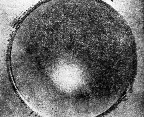
Figure 18 - Olsen draw cup of ductile nickel deposit. Note absence of cracking.
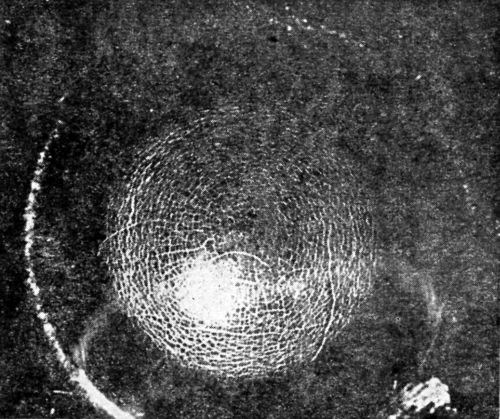
Figure 19 - Olsen draw cup of ductile nickel deposit from solution containing extract from unwashed filter bags.
Recent publications show that others have used and made comments on the Erichsen method or variants. M.H. Corbin76 uses the method to test the adhesion and flexibility of paints. S. G. Clarke64 used another variant to test black lead peroxide coatings. In a series of articles B. Egeberg and N. E. Promisel77,78 make these interesting observations:
"Erichsen deep drawing tests may be used, but are applicable only to flat articles or flat sections of articles of correct gauge for the machine. The results must be cautiously interpreted, however, since the ductilities of both the deposit and basis metal are involved.
"A modification consists in indenting the surface with the ball of a Brinell machine under increasing loads and observing the stage, if any, at which the coating becomes detached.
"Reports indicate very satisfactory results with this type of test on chrome."
In an extensive study of ductility and adhesion of nickel deposits, F.P. Romanoff55 used the Erichsen extruded cup test in which a 1-in. steel ball was impressed to a depth of 0.225 in. This was standard in all cases except where extrusion to fracture was employed. The condition of the deposit on the dome was used as indication of ductility and adhesion. [Fig. 20] illustrates the domes and their use in testing ductility and adhesion. After much work had been done he concluded that this is not a reliable test for adhesion. He then developed a modification which he calls the "flanged cap adhesion test," which he states will always detect poor adhesion. His remarks on these are highly significant:
"We found that whenever poor adhesion was encountered, hard columnar nickel deposits of approximately 0.0003 in. (0.0076 mm) thickness, almost always became detached from the dome during the extrusion test. Heavier deposits of about 0.001 in. (0.025 mm) usually appeared intact. However, separation was more or less easily accomplished if the specimens were sheared and a knife or other implement inserted between the nickel and the base. Notch propagation from the fractured nickel to the copper base was not as severe as in the case of good adhesion.
"When ductile nickel of 0.0003 in. (0.0076 mm) had imperfect adhesion to the base, the appearance of the dome of the extruded cup varied from its normal appearance to that of a decided cracked surface. The large fracture, with its lesser branches, appears more severe than in the hard nickel dome. This effect, however, does not always appear when ductile nickel is extruded. Apparently perfect domes may occur in spite of poor adhesion. The surface appearance is probably a function of the degree of adhesion of the nickel to the base.
"Flexing of the unstressed part of the specimens by bending it caused the nickel to part from the base, close to, but not over the extruded area. This is a rather odd condition which often arises when the poorly adhering ductile nickel will peel at points all over the specimen save on the extruded dome [Fig. 21].
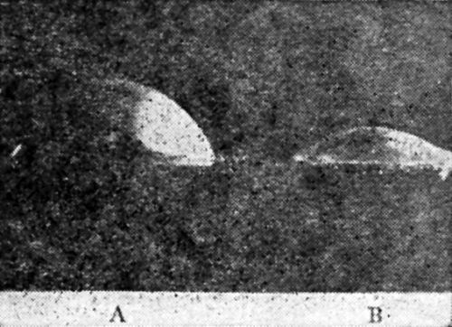
Figure 20 - Erichsen cup test specimens. A shows depth of extrusion, 0.34 in. (8.64 mm) at fracture of ductile nickel, which is the same depth as for unplated Cu base. B shows depth of extrusion, 0.14 in. (3.56 mm) at fracture of hard fibrous Ni over Cu base.
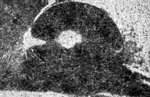
Figure 21 - Flexing of unstressed part of Erichsen cup with poorly adherent ductile nickel produced peeling except on cap of dome.
"The extruded cup test is considered entirely unreliable for determining the degree of adhesion of deposits. The flexure test was more indicative than the extrusion test, but this was also unsatisfactory, because heavy deposits of ductile nickel, about 0.001 in. (0.025 mm), gave no indication of poor adhesion when subjected to either type of these tests."
After Romanoff became convinced that the Erichsen test he had used gave no indication of poor adhesion, he searched the literature for something better, but not finding a test that would answer his purpose, he devised a new adhesion test that also indicated the degree of ductility. It is simply another modification of the Erichsen test.
"As all of the material processed in regular production was to be subsequently fabricated into articles, a new adhesion test was developed, which test also indicated the degree of ductility of the deposit. The test furthermore helped to estimate the maximum deformation permissible before the polished deposit would lose its luster.
"The apparatus consisted of an ordinary punch press with a set of adjustable dies for drawing a flanged cap. The flange is 2.5 in. (63.5 mm) in diameter and the cap 1.5 in. (38 mm) in diameter. The depth of the cap is adjustable from zero to 0.5 in. (12.7 mm). [Fig. 22] shows a full view of a test specimen.
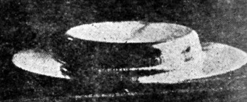
Figure 22 - Flanged cap test specimen stamped from strips cut from regular production sheets.
"Our specimens are usually tested to a point which will fracture the cap. This provides information as to the ductility of the base and adhesion of the electrolytic deposit. The intact part of the draw shows how drawing affects the structure of the deposit. Deposits of nickel over 0.002 in. (0.05 mm) thick will not evidence poor adhesion as readily as do thin deposits and, unless the cap is fractured, may not be detected. Fracturing of the cap will disclose poorly adherent deposits of nickel of almost any thickness.
"The press runs at a speed of 100 stampings per minute. This test has proven entirely satisfactory for testing adhesion and ductility of metallic or non-metallic coatings on base metals of sheet steel, tin-plate, zinc, copper, brass and Monel.
"Conclusion: A test for adhesion and ductility of electrolytic nickel and other coatings on sheet metal by stamping out a flanged cup is more reliable for determining adhesion than any other test used for this purpose."
From the information recorded in the literature one might draw the following conclusions:
- Some form of extrusion test is likely to give valuable information about the ductility of electrodeposits provided the ductility of the base metal is sufficiently high.
- The test as usually carried out is not a satisfactory test for adhesion if the deposit has high ductility.
- As a test for adhesion of more brittle deposits such as chromium and hard nickel it is fairly satisfactory.
- The method is applicable only to relatively thin deposits.
- The particular variant of the Erichsen test devised by Romanoff known as the "Flanged Cap" test may prove satisfactory for testing adhesion even for ductile coatings.
- It is a very rapid test for situations where it gives satisfactory results.
Miscellaneous tests
Several tests are mentioned in the literature which, while excellent for certain types of deposits, have limited application. These have all been grouped under the heading miscellaneous, but will be considered individually.
Scratch tests
Ap Roberts used a scratch test in an article124 on plating on magnesium. His method:
"... consisted of making two scratches through the deposit at approximately a 30° angle to one another and determining the difficulty of lifting the plate with a pointed tool. The results showed that a good deposit would break off, not independently, but with a portion of the base metal adhering."
Several others have used this method as described or with slight variations. One common type of variant is described by C.F.J. Francis-Carter:58
"Make a deep scratch in one direction in the deposit, and then four or five others across it at right angles. Peeling at the points of intersection would indicate poor adhesion, although absence of peeling would not necessarily denote perfectly adherent deposits."
These scratch tests are applicable only to thin deposits. In a private conversation, a representative of one of the large bearing manufacturers described a somewhat similar test which he uses to test the adhesion of very thick deposits. Parallel cuts are machined about ¼ in. apart, then another set at right angles. This leaves a set of rectangular projections. A blunt chisel is then placed against the projections and hit by a hammer. This is a very severe test for a deposit which is hard. Another even more severe test is to break the base metal along one of these cuts and attempt to remove the projection of plated metal by means of a sharp chisel. A deposit that stands these tests is considered perfect.
Chisel test
Another type of chisel test used by Hothersall87 has already been briefly described and illustrated [Monthly Review, 32, 1130 (1945)]. It is sometimes combined with what is called the "saw test" or "hinge test." The test is made by sawing practically through the base metal then bending the uncut deposit back on itself. If the adhesion is not very good, the deposit will pull away more or less from the base metal. In case there appears to be no separation at the fracture by the unaided eye, it is examined by some under a microscope. If this reveals nothing, then a very thin sharp chisel is used in an attempt to separate the deposit while the sample is held in a vise. This is an extremely severe test and indicates weakness when the previous tests fail. It is satisfactory only for deposits thicker than 0.01 in.
F.C. Mesle made an interesting comment on the chisel test in a discussion of a paper118 on the adhesion of thick silver plate on steel. His statements follow:
"I am interested in this question of adherence. Only yesterday at Rock Island, we were discussing this question with engineers who were rather critical of the ability to plate silver on steel and, of course, methods of testing were under consideration. Testing methods are changing. We are now asked to plate a thickness of 0.04 to 0.06 in. (1.0 to 1.5 mm) of silver and for this thickness, the hammer and chisel adherence test is in general use."
This chisel test is mentioned by several in the literature and by even more in private communications. It is applied in various ways and is rather generally considered the most severe that can be made.
Sawing test
Simply sawing the strip having an electrodeposit is used by many as a good test for adhesion. A hard or brittle deposit will flake off and even a soft deposit may pull away more or less. The microscope is often used to permit close observation.
Grinding wheel test
A test somewhat similar to the sawing test, but much more severe, was extensively used by the late E.M. Baker. He describes it briefly in a discussion of an article by C.J. Brockman and J.H. Mote:79
"A crude but effective method of testing the adherence of electrodeposits is to hold the plated article against a rough emery wheel so that the wheel cuts from the base metal to the deposit in a jerky or bumpy fashion in contradistinction to the way in which one would ordinarily grind a piece of metal with a wheel. This is particularly effective on very hard electrodeposits, as apparently this procedure produces a high local stress between the plate and base metal."
Some specify the wheel should be dry and also give the dimension and speed of rotation. This method is at present considered by some of the best platers in the country as a very satisfactory, quick and effective shop method especially for deposits not too thick. It is not considered a good test for deposits of ductile metals.
Another type of grinding test is used by some. It consists in grinding through the deposit with a dry emery wheel. A test much like this is automatically involved in certain types of electroforming in which worn parts are built up to oversize, then ground to correct dimensions. If the deposit adheres at the interface between the original metal and the deposit during the grinding operation, the bond is considered satisfactory.
Cathodic treatment
Several have mentioned the use of what might be called a cathodic treatment test. The plated object is made cathode in a solution from which only hydrogen is evolved. Usually a high current density is used for a rather long time. It is reported that for certain types of deposit and for some base metals, the deposit, after standing for some time, is lifted, usually as blisters. This blistering is hastened by heating. In special cases where adhesion is poor, the deposit is lifted during the electrolysis. The principal argument used in support of this test is that it is nondestructive.
The Mesle "can opener" test
An ingenious test developed by F.C. Mesle in a very extensive research is described by him in an article90 entitled "The Adhesion of Electrodeposits." The following is a description of this test and the manner in which he used it in his own words.
"The test panels were processed so that the deposit could be peeled from the top of the panel, thus giving opportunity to take hold of the deposit and pull. The lb. pull required either to peel or break the plate will indicate the degree of adhesion to the base metal plated. I made a tool that I think has some merit, and that indicates the comparative degree of adhesion, even if it is difficult to express the adhesion in exact lb. per square in. The tool is a slotted ¼-in. drill rod connected to a steel wire coil spring. The plate is peeled (if it can be peeled) after the manner of opening a sardine can. The tension put on the spring is the measure of the load required to peel or break the deposit. Each fraction of a turn is given a number that indicates the load required much the same as the load required to pull the needle from the magnetic surface in testing the thickness of plated coatings. Pull No. 1-2 means that between one and two lb. pressure is applied to ½ in. of plated metal that is being pulled from the base. Pull No. 10 means that more than 10 lb. pull was used. If this load did not peel or break the deposit, the adhesion rating given is 100%. I would estimate that this rating gives at least 2 tons/in.2. I realize there are too many factors that can change that make it difficult to be sure that the lb. pull is that which the test indicates. If the pull is not applied evenly the plate may tear rather than break. The same is true if the adhesion is uneven where the pull is exerted; the plate will tear rather than break. These factors would indicate less than the real adhesion. I think a fair comparison can be made of the degree of adhesion between various samples tested.
"If the plate peels at less than pull No. 1, it is rated as very poor or 5%. 1-2 poor, or 15%; 2-3 fair or 25%; 3-4 good, or 35%; 4-5 at 45%; 5-6 very good or 55%; 6-7 at 65%; 7-8 excellent or 75%; 9-10 at 95%; and 10 perfect or 100%. To apply the maximum load of No. 10 pull, the deposit should be at least .005-in. thick; because it was convenient I built this thickness with silver; high speed copper, could no doubt be used. Bright. nickel, too, is brittle, and it will break rather than bend around the ¼-in. drill rod.
"A deposit rated as fair or better could be considered as satisfactory for general purpose plating, but it is suggested that plating methods that produce perfect adhesion should be the goal of everyone going to do quality plating. The nearer we approach this goal, the lower the percentage of failures due to poor adhesion."
In the hands of a single person this method is capable of giving relative semi-quantitative results. Another person using the same method would probably not obtain the same values. By more intensive study and careful designing and by the introduction of a method for measuring the actual force in lb., still more quantitative results might be obtained. Serious difficulties would arise, however, if one were to attempt to interpret such data in terms of psi, or even in terms of lb./in.
The Jacquet test
A method somewhat similar to this but possibly more elegant was developed by Pierre A. Jacquet.82
"A clear understanding of the principles of adhesion of an electrodeposit to the basis metal is important from both a purely scientific as well as a commercial point of view. At present the adhesion is estimated merely qualitatively. Thus, coatings on metal sheets are tested either by repeated bending or by cupping. Quantitative measurements are possible by Ollard's method, but his method is adaptable only to very thick deposits, (minimum 2.5 mm or 0.1 in.), which greatly reduces the usefulness of the method, since the usual deposits are at most a few tenths of a mm thick. Moreover, Ollard's method requires special test specimens, very carefully prepared.
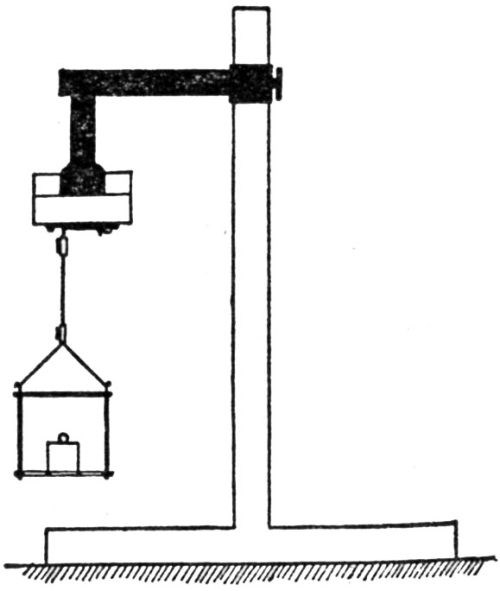
Figure 23 - Schematic view of Jacquet's adhesion tester.
We have endeavored to adapt our method [Fig. 23] to determinations of the adhesion of any electrodeposit on any basis metal. For example, take a steel basis plate with an electrolytic nickel deposit. The adhesion of the nickel deposit has to be tested. The area ABCDIJ [Fig. 24] is marked on the nickel plate with a suitable engraver's tool. The rest (shaded area) of the plate is varnished. The area ABCD is dipped into a protein solution and then rinsed. The plate is then completely immersed as cathode into a copper bath and copper is deposited on top of the nickel to a thickness of about 0.30 mm (12 mil). The copper deposit does not adhere to the part ABCD on account of the protein film, and is easily lifted, but the copper strip GHIJ shows normal adhesion. If this adhesion is stronger than the adhesion of the primary nickel coat to the steel base, this nickel strip will be detached by the method shown in [Fig. 23]. Before applying the test, it is necessary to groove or scratch the nickel coating along GH underneath the copper deposit.
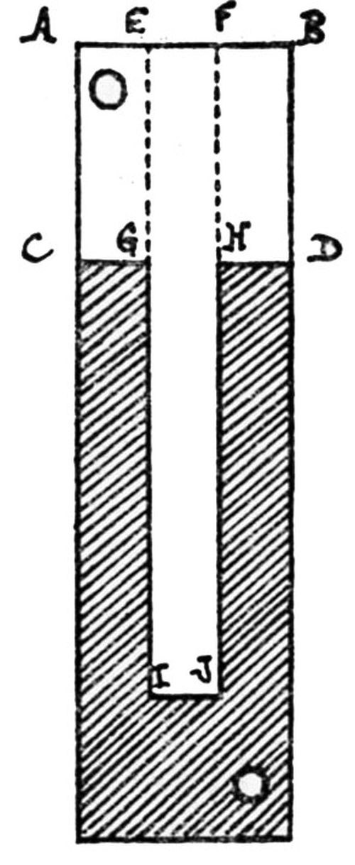
Figure 24 - Jacquet's cathode plate for measuring shearing stress and adhesion.
"Our experiments have shown that this adhesion test is applicable to poorly adherent nickel deposits only, e.g., for those on steel, which had been pickled in a cold 50% hydrochloric acid solution. When nickel adheres well, it is impossible to detach it, the adhesion of copper to the nickel or the tensile strength of copper itself not being strong enough. By our test, the copper will separate from the nickel. Accordingly, we set out to find a more adherent copper deposit.
"In carrying out the adhesion tests, whenever the necessary weight exceeded 2 kg, a lever device was made use of, as shown in [Fig. 25]. There is, of course, an upper limit in weight which corresponds to the tensile strength of the copper strip; too thin a strip will pull apart before the nickel deposit is separated from the steel."
This has since been referred to by others as Jacquet's method.
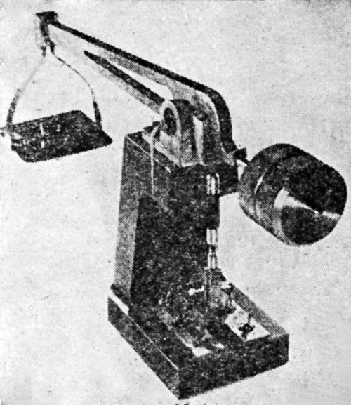
Figure 25 - Jacquet's improved adhesion tester.
Quantitative methods
The Burgess method
It is interesting to note that the man who proposed the first tests for adhesion included one of a really quantitative nature. This test was designed to determine the adherence of a zinc coating applied by the hot dip process. It is; however, equally applicable to electrodeposited coatings. This first method is described by C.F. Burgess in his article1 as follows:
"There seems to have been no work previously done in determining the degree of adherence of zinc coatings, and, inasmuch as such determination seemed desirable, a method of testing this property was devised along the following lines:
"The method consists in soldering to the zinc surface, by means of a low-melting solder, a copper plug one-half in. in diameter. By noting on a spring balance, the pull necessary to separate this plug from the iron, a measurement of the adherence of the zinc to the iron is made. The zinc adheres, by means of the solder, to the brass plug with a greater strength than to the iron. By this apparatus, which is illustrated in [Fig. 26], a fair degree of uniformity of measurement was obtained and the relative adherence of different kinds of coatings derived.
"An error may possibly come into this test from the fact that the sample must be heated to a point sufficiently high to cause the solder to adhere. This heating undoubtedly decreased the adherence of an electrolytic zinc coating to the iron, while it does not decrease in like degree the adherence of the coating which has been applied by the hot process. It may also be suggested that a very porous coating will allow the solder to penetrate through the zinc and adhere directly to the iron, thus giving an erroneous value. This was found, however, not to be the case.
"There is some tendency for the solder to run out from the edges of the brass plug and thus adhere both to the brass and the surrounding zinc, increasing the force necessary to pull the plug away. This error was eliminated by cutting away such surrounding solder. To avoid that operation, the method of soldering shown in the accompanying sketch [Fig. 26] was adopted. The galvanized iron was held between two aluminum plates, one of which has an opening into which the brass plug fitted. By applying the solder in this opening, and then applying the brass plug, the adherence was effected without the solder flowing on the zinc surface not covered by the plug."
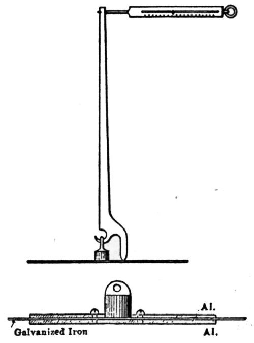
Figure 26 - Burgess' adhesion tester. Top: test in progress. Bottom: method of soldering.
Throughout the period from 1905 to the present, this general method with slight variations has been mentioned many times in the literature. During about the first half of this period the method was seriously discredited because of the feeling that the high temperature involved in the soldering operation changed the degree of adhesion. During the last half of the period there has been a very active controversy over this point. One test for adhesion that had been in common use was to heat the object, which caused blistering in the case of poor adhesion. In fact, this test is now specified by the government in some cases. The feeling at first was rather general that heating decreased the adhesion. Eventually much evidence appeared which indicated very strongly that heating increases adhesion, at least in some cases. Probably the most extensive study of the question was made by F.C. Mesle. In an article69 published in 1936 he states:
"The most satisfactory test for adhesion of the plate is to solder a piece of metal to the plated surface, then pull it off. This method should be developed to a point where the adhesion can be expressed in pounds per square in. or such other factor."
After more thorough investigation he revised his opinion. The following is a very good summary in his own words taken from an article96 published in 1939:
"I once wrote an article on 'Plating to Specifications' and in it suggested what I thought was a good test for adhesion. I also thought the idea was original with me; since then, I have learned that I was wrong in both assumptions. The idea was to solder a lug on the surface to be tested for adherence, then pull it off. I even rigged up a gadget so that I could measure the pounds' pull required either to fracture the solder or peel the deposit from the base. When I first sought to get advice from authoritative sources, I was told that the heat required to solder the lug to the plated surface would affect adversely the adhesion of the deposit. Therefore, the test would be without significance. I tried to discover if the heating did affect adversely the adhesion of the deposit by heating test pieces to temperatures higher than required to do soft soldering. In some instances, I heated the test pieces to a red heat, and found that after this heating the adhesion was as good as before, and I concluded that the test was satisfactory, and proceeded to use it. But the results were not satisfactory, because sometimes, I was sure the tests should show peeling, but it didn't.
"I suppose that because I had been told that heating would affect adversely the adhesion of the deposit, it did not occur to me that heating might improve the adhesion. I have been asking platers this question: 'Does heating, after plating, to a temperature of from 300°F to 1,000°F affect adversely the adhesion of the deposit?' Most of the platers answer in the affirmative. Hothersall37 and Mathers86 called attention to an improvement in adhesion after heating, Mathers to silver on steel at 1,000°F for 2 hr, and Hothersall to nickel on brass at a lower temperature of from 100 to 250°C for 2 to 4 hr.
"In general, platers are of the opinion that heating causes blistering of the plate, and it does, but only when the plate is poorly adherent to begin with. Heating may show up a deposit of poor adhesion, much like chromium plating would cause peeling of the nickel plate upon which it deposited. Heating, like chromium plating, may set up strains that will lift a poorly adherent deposit; to the extent that this strain lifts the deposit, it may be said that heating causes peeling, or it might be more correct to say that heating reveals the fact that the deposit does not have very adherent qualities. Heating could be used as a test for poorly adherent deposits.
"If a deposit will lift from the base when heat is applied, that deposit is decidedly unsatisfactory from an adhesion standpoint. If the deposit is adherent enough to withstand the slight strain produced by heating to lift it from the base, then heating will not affect adversely the adhesion of the deposit, but will greatly improve the adhesion of many poorly adherent deposits, and will completely arrest the peeling of a deposit that had only a fair degree of adhesion before the heat was applied. The surprising thing to me is the influence that comparatively low temperatures really have on the degree of adhesion of some metals (There are some exceptions to the above which will be noted later). These facts spoiled my solder test method completely, so what I thought was a good idea has gone wrong."
From recent private communications, it is evident that the method is being used at present by some of the largest companies and is considered a good quantitative test.
The Ollard method
The method which has ultimately developed into the most quantitative means for determining the degree of adhesion in psi was first described by E.A. Ollard:14
"Since electrodeposition has been used for the salvage of machine parts, tests have from time to time been made on the adhesion of the metal deposited. These have mostly taken the form of pulling in a tensile machine a collar of metal from the shaft on which it was deposited. Such a test is fairly satisfactory for engineers, as provided the work is of this form it gives a measure of what it may be expected to stand. A test of this nature was made by the National Physical Laboratory and gave the following results (Fescol Trade Pamphlet):
Area 0.675 in.2
Breaking stress 11.95 tons
Breaking stress 17.6 tons/ in.2
"An experiment of this nature, however, is really no test of adhesion because it will be readily seen that if a collar of metal be shrunk on to a rough shaft, it will resist pulling off, although there can be said to be no adhesion between the metals. Now these conditions are exactly comparable to those that are obtained by depositing a metal collar on a shaft, because we know that there is quite a considerable tension produced in depositing a metal, and the shaft is usually first roughened by pickling. Cases may and do occur, therefore, in which a collar that cannot be pulled from the shaft on which it has been deposited will, on being cut longitudinally, strip away quite easily.
"Various experimenters have from time to time tried or suggested methods of pulling a deposit straight off its base metal. Some have suggested soldering a piece of metal to the deposit in order to pull it but it seems that any test involving heating is open to the objection that the adhesion may be affected by temperature.1
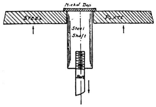
Figure 27 - Ollard's adhesion test, first method.
"The author considers that the only satisfactory method is to obtain a deposit thick enough to be gripped in the machine. To do this, a piece of steel rod, 1 in. in diameter and about 2 in. long, was taken and, after being waxed all over except at one end, it was pickled as described above. It was then hung horizontally in the nickel bath and the deposition started under conditions before found to be the most favorable. The deposition was allowed to proceed for 250 hr starting at 2V, and running up to 4V after about a quarter of an hour with a current about ¼ A. The pH was about 3.5. The specimen was then taken out of the bath and placed in the lathe, and all the nickel that had deposited over the edge turned off. This left an end of nickel on the rod over-hanging by about ¼ in. The bottom of the rod was then screwed to take a ½-in. rod and the specimen was put through a 1-in. hole drilled in a steel plate. The plate was then placed across the top of a tensile machine and the ½-in. rod gripped in the lower jaws of the machine [Fig. 27]. In this way, the deposited nickel could be pulled straight off the steel. The deposit pulled at a load of 9,320 lb., which gave a stress of 5.71 tons calculated over the whole area. Small particles of the steel appeared to have pulled away with the nickel. A photograph of the test piece after pulling away is shown in [Fig. 28].
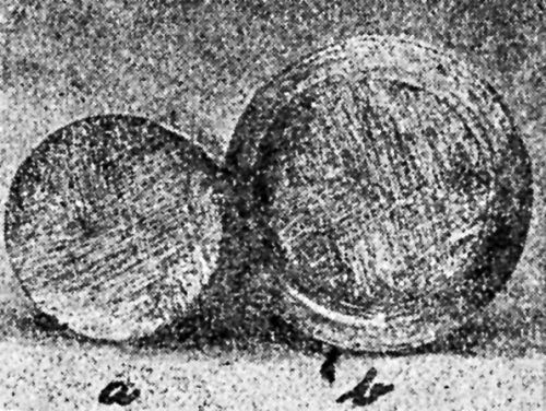
Figure 28 - Ollard's adhesion test sample after fracture: (a) steel shaft, (b) nickel deposit.
"As the outside of the nickel would pull away before the middle, it is probable that the stress was greater than that calculated. A second experiment was therefore made similar to the first except that a ½-in. hole was drilled down the middle of the deposit into the steel. Thus, it was only to deal with the stress over the outside rim of ¼-in. width. Unfortunately, this deposit did not adhere satisfactorily over the entire area, but calculated over the area of adhesion, the stress was 6.6 tons. A large piece of the steel was still adhering to the nickel and some of the nickel remained on the steel. Neither of these tests, however, gave results as high as might have been expected from an examination of the test piece. As the test piece did not fail entirely at the line of demarcation of the two metals it seems to show that the adhesion in parts must have more nearly approached that of the solid metal crystals. Accordingly, two more specimens were prepared.
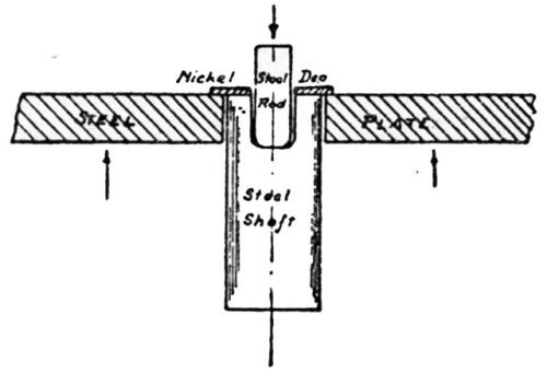
Figure 29 - Ollard's adhesion test, second method.
"In the first of these a ¾-in. hole was drilled; it was then pulled in the same way, a ½-in. bolt being used. This bolt failed and the hole was 'tapped' 5/8 in. and a 5/8 bolt substituted. This also failed and a nickel steel rod was substituted. With this a load of 23,800 lb. was obtained on an estimated area of 0.297 in.2, giving a load of 35.8 tons/in.2 at the joint. The bolt then failed, the deposit having cracked. A piece of the steel was then placed through the hole on to the steel, and the steel pushed off [Fig. 29]. The load in this case was 18,400 lb. giving a stress of 27.7 tons/in.2. The specimen did not fail at the joint, part of the steel being left adhering to the nickel. On examination, it was found that the nickel had not been machined quite far enough up the line at the edge and this may have given a rather high value. The second specimen was drilled with a 21/32-in. hole and the nickel machined as above. In this case, the area was .353 in.2, load 15,050, stress 19.10 tons/in.2. Again, part of the steel was left adhering to the nickel."
The presentation of this paper by Ollard was followed by a discussion in which some interesting remarks were made concerning the method. Some of the points brought out and suggestions offered are so pertinent that the whole discussion is included here.
"D.J. Macnaughtan said he believed that this was the first record of tests on the adhesion of deposited metals in which the adhesion was determined by pulling the deposit directly off the base metal. A number of adhesion tests had previously been made by Schlotter in which the deposit was soldered on to a block of other metal which was subsequently pulled. The heating of the deposit during soldering was a drawback to this method. The method employed by the author necessitates a deposit of sufficient thickness to withstand the shearing stress produced at the edges of the deposit while it is being tested for adhesion. The author was to be congratulated upon having obtained some definite results, although more were to be desired.
"He, himself, had made a number of tests of the type referred to in which a deposited collar is pulled off a shaft. He did not agree that it was impossible as a result of tension in the deposit to pull off such deposited collars even when the actual adhesion was poor. In these circumstances, the deposit could generally be pulled off with a stress of 3 to 4 tons/in.2, while if the adhesion was good more than 17 to 18 /in.2 stress was necessary. Such a test was of value to engineers although he agreed that it did not measure the actual force of adhesion.
"With reference to the actual results obtained by the author, he was inclined to think that the figure of 36 tons/in.2 obtained in the third experiment was too high, as it seemed probable that before such a stress was reached either the nickel or the underlying steel, which he believed was mild steel, would stretch and break independently of the strength of the junction of the nickel and steel. He was of the opinion that the fourth result, 19 tons/in.2, was probably nearer the mark. The results, however, show the high degree of adhesion obtainable by the methods employed and explain the increasing use of nickel deposited upon steel for engineering purposes.
"H. Sutton said there was one point which had struck him in connection with this method of testing. Mr. Ollard would probably have found that in testing a joint of the kind he had been dealing with, it was necessary to have the stress applied exactly normally to the plane of the joint. It was known that in testing strips of material, a small eccentricity or a small error in the direction of the applied stress in the tensile test was likely to have an appreciable influence on the final result. The final result might be low owing to the nature of the loading. If such an error existed in the case of Mr. Ollard's work it would, in his opinion, give a false result on the low side. Prof. A. Robertson had designed a set of axial loading shackles for tensile testing and the load was applied through two hardened steel balls. In tests of the kind described by Mr. Ollard, it should be possible to apply the tension stresses normally to the surface under test with a similar device.
"E.A. Ollard, in reply to the discussion referring to the remark by Mr. Macnaughtan as to 17 or 18 tons being the highest stress likely to be obtained, owing to the fact that nickel itself began to yield at about that stress, said he had built up a small piece of nickel deposit in the same type of bath as the one mentioned in the paper and the figures obtained were an ultimate breaking point of 43.7 tons, a yield of about 39.3 tons, and elongation of 25%."
D.J. Macnauhtan39 made the following remarks concerning Ollard's method:
"I remember the great pleasure it gave me, when some years ago, Mr. Ollard called at Woolwich and showed me a piece of steel and a ring of nickel which had been separated by a direct pull in a tensile testing machine. It was the first really quantitative adherence test for electrodeposits which had been introduced. We made much use of this test and found it invaluable. You all know the extremely interesting results which Mr. Hothersall obtained in his investigations in the adhesion of nickel on brass, in which this method of testing was freely used."
In 1927, C.H. Faris19 described a quantitative method similar in some respects to the Ollard method. In fact, Ollard makes some remarks about tests much like those described by Faris. So far as can be detected, however, these men worked independently without being familiar with each other's work. The method used by Faris is sufficiently different from Ollard's to include it here.
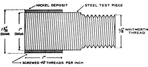
Figure 30 - Faris' first adhesion test specimen.
"To prove definitely this all-important question of adhesion, a steel specimen was prepared of a form shown in [Fig. 30], and submitted to the National Physical Laboratory with a request to remove the deposit from the steel and record the pull required to do so. The plain portion of the steel plug, one in. in diameter, was built up by deposition of nickel; then a fine pitch screw having 40 threads/in. was cut upon the nickel, final diameter over the tops of the threads being 1-5/32 in. The length of the portion carrying the nickel was, at the commencement of the test, one in., the maximum thickness of deposit at the thread tops .078 in., while the minimum thickness at the root of the thread was 0.62 in. A 7/8-in. Whitworth standard thread was cut on the other end of the steel plug, on which was fitted a steel holder, another steel holder being fitted to the already-mentioned fine thread on the nickel. The specimen was then subjected to a pull in the same manner as a tensile test piece would be pulled. At a load of 10 tons/in.2, no breaking down of the adhesion was observable.
"With the object of reducing the pull required, the superficial area was reduced by turning away the nickel until the former length of one in. became only a narrow collar .215 in. in width, as shown in [Fig. 31]. Again, the load was put upon the test piece in the manner described; at a load of 6.74 tons the thread of the steel holder, which was attached to the 40-thread screw on the nickel, sheared and left the test piece, the nickel thread remaining intact. The steel holder which failed showed, under a scleroscope test, a hardness number of 28.
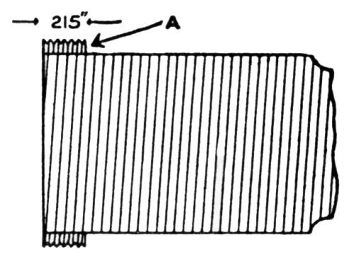
Figure 31 - Faris' second adhesion test specimen.
"Thus far the desired information had not been obtained, so to carry the test to finality a special steel holder was employed, which, instead of fitting on to the fine thread, placed the load directly upon the end face of the nickel deposit A in [Fig. 31]. At a load of 11.95 tons, the ring of nickel was pushed from the steel plug, and subsequent calculation showed that the pressure required to move the deposit was 17.6 tons/in.2. The nickel came away from the steel in the form of a ring, broken at one point only in its circumference, and on the inner surface a film of steel was found to be amalgamated with the nickel, proving that even at the load stated, the adhesion was greater than the skin of the steel could withstand, thus the steel sheared.
"It will be noted that the application of the load in the manner described left the thread perfectly free from any compressive force, so tending to restrict its movement at such a time as the adhesion should give way, and it may be assumed, therefore, that the adhesion between the two metals was not in any degree assisted by the presence of a steel holder tightly encircling the thread on the outer diameter of the nickel deposit.
"A bar of 1-in. bright drawn steel was increased in diameter by nickel deposition to 1¼ in., shimmed up true on the diameter, and short lengths parted off, ¼ in. in thickness. Such a specimen was subjected to a punch and die test in the laboratory of one of the large steel works in the North, and in that instance a load of 18 tons/in.2 was required to push the steel core from the nickel ring, and again the same result was observable, namely, the steel sheared and a film of steel adhered to the nickel.
"A further case may be cited of a similar specimen which was dealt with in precisely the same manner. The load in this case, however, on calculation, proved to be just over 24 tons/in.2, and again the shearing effect on the skin of the steel was observed."
C.H. Faris describes another experiment so unique and practical and carrying such a demonstration of certain possibilities for electroplating that it is included here:
"A gear-box shaft taken from a four-ton petrol-engined vehicle engaged on goods transport, provides an interesting example of the adhesion obtained, and in this instance the test took the form of severe service conditions as an alternative to a laboratory test. On the shaft being dismantled it was found that the splines at one end had been sheared away, so after a preliminary rough grinding operation on the portion involved, the diameter was increased 3/8 in. by means of electrodeposition. Subsequent machining produced the finished piece as shown in [Fig. 32], where it will be seen that the splines consist of solid deposited nickel, their dimensions being ¼-in. wide and 5/32-in. deep, the diameter of the shaft over the splines being 1-3/8 in.
Figure 32 - Faris' shaft for service adhesion test.
"During the spline-milling operation, the cut was intentionally taken deeper than the standard, in order to remove all nickel from the roots of the grooves or keyways, thus breaking up the band of nickel into six separate portions, each approximately equal in width to 1/12 of the circumference. By this procedure the test for adhesion was accentuated, as each individual spline was subjected to the strain without deriving any additional strength from the presence of a complete band of nickel encircling the shaft at that part.
"It has been shown that the treated portion of the shaft was ground true prior to the treatment, but it should be mentioned that such is not usually necessary, the reason in the case under consideration being to make the ultimate test as severe as possible by removing all traces of the former splines, proving that no anchorage is necessary other than that which the process itself provides. Therefore, no mechanical preparation of the surface of the metal to be subjected to this treatment, such as roughening, drilling holes, or cutting grooves is required, as, providing that the metal is free from scale and sound, the cleaning bath creates the desired result and ensures adhesion.
"Reports have been received from time to time with regard to the shaft just described, from which it appears that very little wear, no deformation, and no evidence of loosening of the deposit have occurred during the several years of subsequent service."
A.W. Hothersall whose efforts have been devoted largely to studies on adhesion, including methods for measurement, appears to have adopted Ollard's as the best quantitative method. In an article43 on "The Adhesion of Electrodeposited Coatings on Steel" he remarks as follows:
"The most satisfactory quantitative test so far developed is due to Ollard;16 the form of this test as used by the author is illustrated in [Fig. 33]. With careful use, this test is capable of providing valuable data of a relative nature although as a method of yielding absolute values it is open to certain objections. For example, concentration of stress at the outer edge of the junction of deposit and basis metal will result in a tearing action and a low result for the adhesion. Ollard showed that as the diameter of the central hole drilled in the test piece was increased relative to the outside diameter, higher results were obtained. Local stress concentration may also result from too thin a deposit or too loose a fit of the test piece in the supporting bushing. The possibility, leading to too high a result, of binding of the test piece in the bushing during loading, caused by too tight a fit initially, must be guarded against."
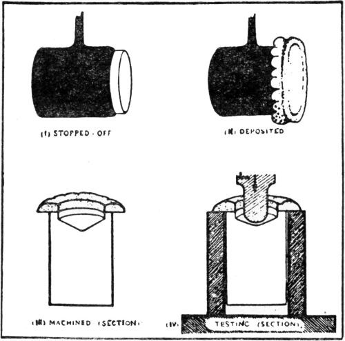
Figure 33 - Preparation and testing of Ollard's adhesion test specimens.
Ring and plug test
In a later article83 published in 1938, Hothersall and Leadbeater describe a modified form of the Ollard method, which is simpler, requires less machining and can be used for somewhat thinner deposits (about 0.015 in.):
"A mild steel rod, 0.5 in. in diameter, was faced at one end in the lathe and accurately fitted with a machined steel bush, 1 in. in diameter, 0.25 in. in thickness, the end of the rod being flush with the end of the bush. Tin was then electrodeposited from the acid bath to the required thickness on the composite face of the rod and bush. The tin coating was fused in a flame, the bush being twisted after cooling to ensure that it was free. After stopping off as shown in [Fig. 34], the specimen was subjected to some or all of the treatments outlined below and nickel was deposited to a thickness of 0.03-0.04 in. (0.07-0.1 cm). The test piece was inserted in a tensile testing machine, flexible connections of stranded steel wire being made to the jaws of the machine to ensure axial loading. The load was applied at an approximately uniform rate of 0.03 tons/min and eventually resulted in fracture of the tin, the rod pulling out leaving the disc of nickel upon the bush. The load was then noted and the adhesion in tons/in.2 calculated from it."
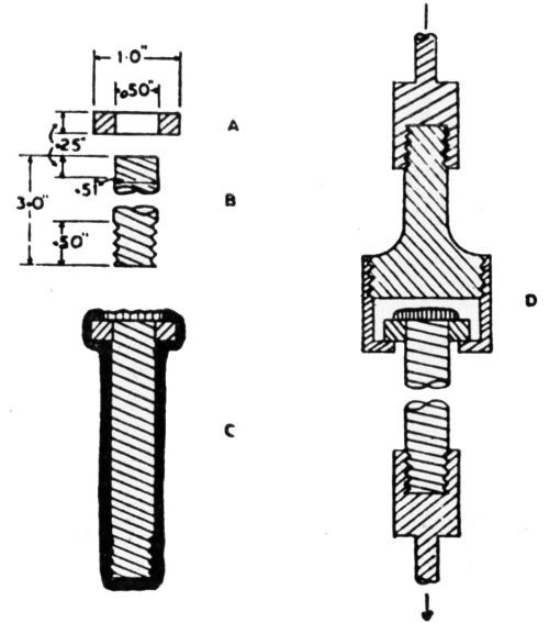
Figure 34 - Ollard's adhesion test as modified by Hothersall and Leadbeater: A bush, B rod, C stopped off specimen after deposition, D specimen assembled in adaptor for test.
Roehl's modification of Ollard method
The most recent published modification of the Ollard method was by E.J. Roehl, of the Research Laboratory of the International Nickel Company in 1940.107 His description follows:
"The problem of the adhesion of deposit to basis metal is one of primary importance in all types of plating, but in the field of heavy nickel deposits for the building up of worn or mis-machined parts and for the protection of parts against combined wear and corrosion, good adhesion is a first requisite.
"Of the various tests which have been devised to determine quantitatively the degree of adhesion of electrodeposits to basis metals, the method due to Ollard,16 and applied by Hothersall43 is the most satisfactory. The present paper describes a refinement of Ollard's test by more closely defining the dimensions of the test piece so that when the deposit and basis metal are separated, the break occurs more nearly by tensile separation.
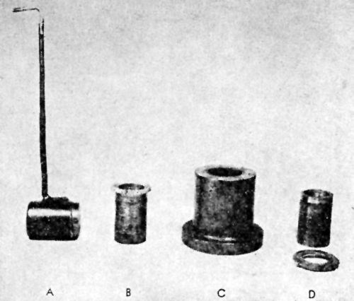
Figure 35 - Preparation and testing of Ollard's adhesion test specimens modified by Roehl.
"[Fig. 35] shows the various steps in the Ollard test method. A machined test piece, 1.00 in. in diameter by 1.50-in. long, is fitted with a connection wire; the whole specimen is stopped off with Halowax and the wax then removed from a portion of the surface as indicated in A. The piece is cleaned by the method it is desired to study and an electrodeposit approximately 0.10-in. thick formed on the exposed end. The wax is then removed and the piece machined to give a total length of 1.51 in. from the unplated end to the underside of the nickel deposit; that is, 0.01 in. of nickel is machined off so that no nickel will remain on the cylindrical surface of the test piece itself and the interface between nickel and basis metal will be well below the shoulder of the finished specimen. At the same time, a hole ¾ in. in diameter by about 3/8 in. in depth is drilled through the nickel and basis metal, as indicated in B. The test piece is then supported in the die C and a load applied by means of a rod in a tensile machine. D indicates the appearance of the test piece after the nickel ring has been forced off. From the value of the load and the area of contact between deposits and basis metal, the adhesion in terms of psi can be calculated.
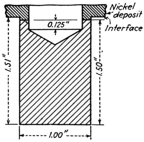
Figure 36 – Finished dimensions of Ollard’s test specimens as modified by Roehl.
"[Fig. 36] is a cross-section of a test specimen just prior to breaking in the tensile machine. [Fig. 37] shows the specimen obtained under treatment No. 2. It can be seen that the break occurred entirely in the cast iron."
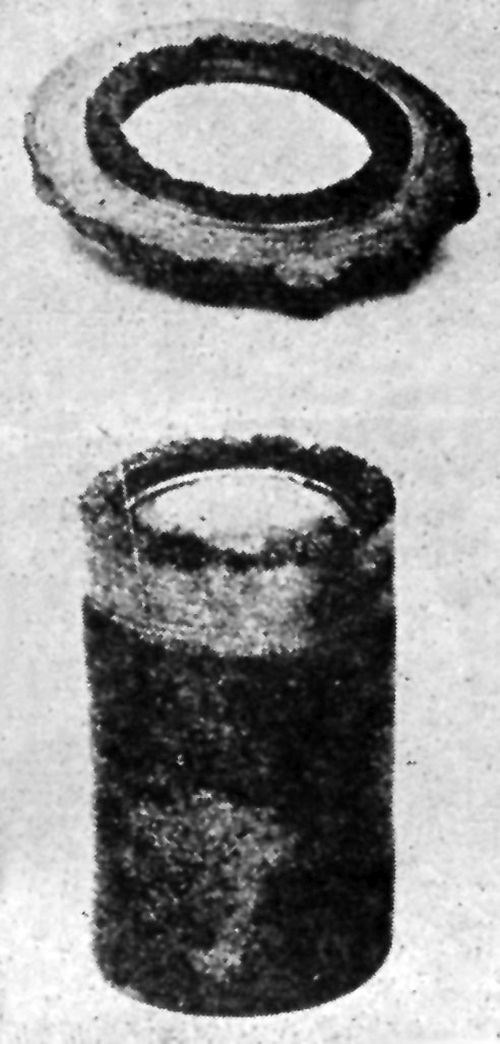
Figure 37 – Ollard-Roehl test specimen after fracture.
Micro-adhesion modification of Ollard method
The final perfection of the Ollard method to date was recently made in the research laboratory of one of the leading automobile manufacturers. It is referred to as a micro-adhesion method. This method has several points of improvement over the standard Ollard method. It employs much smaller specimens and can be used where the deposit is on a curved surface, is relatively fast and can be used on thinner deposits. The area under test is determined by using a micrometer to measure the outside diameter, and a filar micrometer attachment on a microscope to measure the wall thickness. The estimated accuracy is plus or minus 3.5%.
RELATED CONTENT
-
Deoxidizing Aluminum as a Pretreatment
This important first step can help prepare the metal for subsequent surface finishing.
-
Fixing Corrosion Between Anodized Aluminum and Steel
Anne Deacon Juhl, Ph.D., with AluConsult, says Galvanic corrosion is due to an electrical contact with a more noble metal or a nonmetallic conductor in a conductive environment.
-
What is Electrocoating?
E-coat can produce uniform finishes with excellent coverage and outstanding corrosion resistance.


