Aluminum Anodizing
Types of anodizing, processes, equipment selection and tank construction.
#basics
Anodizing is one of the most common surface treatments of aluminum. In all anodizing processes, the basic reaction is conversion of the aluminum surface to aluminum oxide. The aluminum part, when made anodic in an electrolytic cell, causes the oxide layer to become thicker, leading to better corrosion and wear resistance. For decorative purposes, the oxide layer formed on the surface can be dyed.
There are several types of electrolytically formed anodic coatings. The basic classifications for MIL-A-8625 are:
Featured Content
Type I—Chromic acid anodizing: Conventional coatings formed from a chromic acid bath. Chromic anodize coatings are principally used for aerospace applications requiring corrosion resistance and good paint adhesion.
Type II—Sulfuric acid anodizing: Conventional coatings formed from a sulfuric acid bath. Sulfuric anodizing is the most commonly used and most suitable process for coloring.
Type III—Hard coat anodizing: Low-temperature bath and higher current densities to produce thicker coatings, which provide greater wear and abrasion-resistant surfaces. Type III anodize finishes can be dyed or non-dyed.
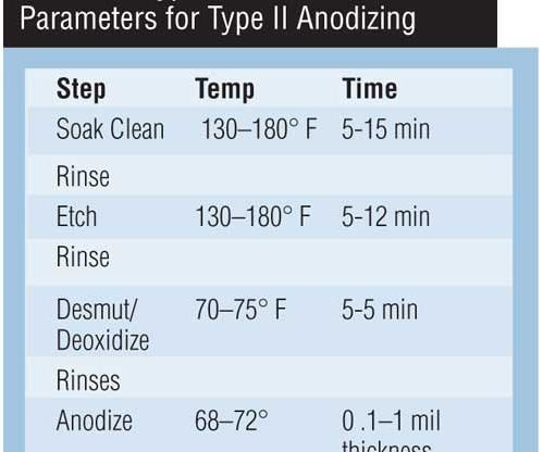
The selection of anodizing equipment should be made with consideration for the process to be used. While operating parameters may vary, a typical Type II sulfuric anodizing process is shown in Table I.
| Step | Temp | Time |
|---|---|---|
| Soak Clean | 130-180º F | 5-15 min |
| Rinse | ||
| Etch | 130-180º F | 5-12 min |
| Rinse | ||
| Desmut/Deoxidize | 70-75º F | 5-5 min |
| Rinses | ||
| Anodize | 68-72º F | 0.1-1 mil thickness |
Anodizing Process and Equipment
The rate of formation of anodic coating is dependent on the current density. Generally, alloys that respond well to anodizing such as 6061 and 6063 will follow the “Rule of 720,” meaning that it will take 720 amp-minutes to produce a 25-µm (1.0-mil) anodic coating thickness on 1 square foot of surface area.
The following formula serves as a guide for estimating the anodizing time for the desired coating:
Anodizing time (min.) = Mils of coating desired × 720/current density (asf)
For example, it will take 36 minutes to produce a 1-mil thickness at a current density of 20 asf.
Tank Construction
Polypropylene is the generally accepted material for construction because of its broad range of corrosion resistance. Most tanks are fabricated from stress-relieved polypropylene using fusion-welding hot forming equipment to eliminate vertical welded tank seams.
Tanks can be fabricated from 1/2- to 1-inch thick stock, depending on tank size. External reinforcements are added as required for strength.
Bath cooling. In the anodizing tank, the temperature must be maintained within the specified parameters. Sufficient cooling needs to be installed to ensure tank temperature does not vary more than a couple of degrees during anodizing. The following formula can be used to determine the heat load generated by the rectifier:
Amps × volts × 3.412 = btu/hr
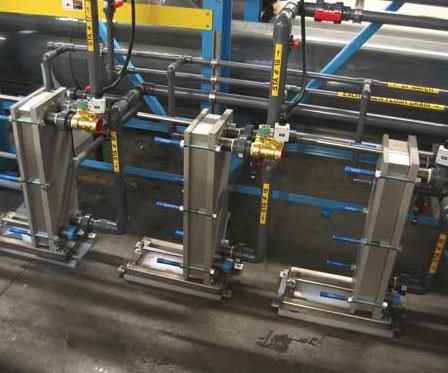
Cooling is generally accomplished by water chillers that circulate chilled water from a reservoir to either an immersion coil in the tank or an external heat exchanger. In hard-coat applications, the coolant is a water/glycol mixture, due to the lower operating temperature of the bath.
Rectifiers. DC rectifiers for conventional anodizing range from 18 to 24 V. Current output is from 12 to 24 asf. Hard coat applications require up to 75 V at 24–40 asf.
Rectifier control options include current control, voltage control and adjustable ramping to gradually ramp up as the oxide film thickness builds. Generally, SCR-type rectifiers are used and will maintain 5 percent or less ripple at full-rated output. Options are available for air- or water-cooled models.
Cathodes. DC rectifiers for conventional anodizing range from 18 to 24 V. Current output is from 12 to 24 asf. Hard coat applications require up to 75 V at 24–40 asf.
Rectifier control options include current control, voltage control and adjustable ramping to gradually ramp up as the oxide film thickness builds. Generally, SCR-type rectifiers are used and will maintain 5 percent or less ripple at full-rated output. Options are available for air- or water-cooled models.
Agitation. The pressure requirement (P) can be calculated using the following equation: P = 0.43TD + 0.75, where T is solution depth in feet and D is specific gravity of the solution. The air is dispersed near the tank bottom through air “sparger” pipes with
3/32-inch diameter holes staggered every 6 inches at 90 degrees apart. A typical sparger will produce a 6- to 9-inch zone of effective agitation.
Agitation can also be provided by pumping the solution. Pumps should be sized to provide 4 to 6 tank turnovers/hr. Eductors can be used to enhance solution flow at the workpiece. Exhaust ventilation is required to capture fumes generated at the tank. Hoods fabricated from PVC are generally used.
Ventilation can be lateral exhaust consisting of a slot hood that controls emissions by pulling air across the tank , or a push-pull, which consists of a push jet located on one side of the tank with the hood on the other.
Push-pull systems are often used because they require less total air. In such systems, the push jet captures the emissions and “carries” them to the hood, resulting in reduced volume requirements per unit of open tank surface area.
Racks. The most common rack materials are aluminum and titanium. Aluminum racks are commonly 6061-T6 or 6063-T6 material. The aluminum will anodize along with the work and therefore must be stripped after each use. Titanium racks are fabricated from commercially pure titanium and have a higher initial cost but eliminate the stripping process. Many styles and types of racks are available; the significant feature of the rack design is the ability to carry sufficient current to the workpieces.
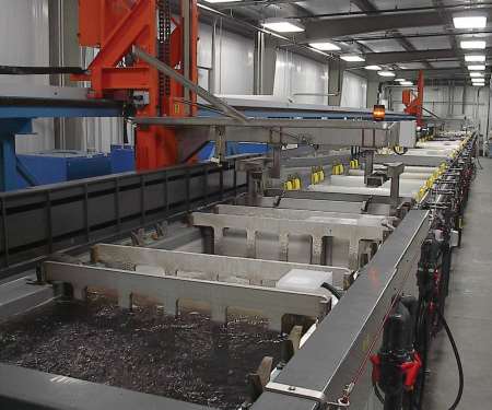
Material handling. Moving racks through the process steps can be done in various ways. Often it is done manually or with the assistance of an overhead chain hoist. Today, several hoist options are available that significantly simplify material handling and can be operated manually but semi-automatic or fully automatic options are available to provide better and more consistent results. These include sidearm, overhead and rim-runner designs.
A sidearm hoist is a cantilevered design that runs along the backside of the tanks to life loads of 250–750 lbs. Overhead hoists can handle larger loads from 2,000 to 4,000 lbs., while rim-runner designs use rails near the tank rim. They are most often used in applications where headroom is limited.
Most hoists use AC motors with variable- frequency drives for horizontal and vertical movements. Positioning is accurate and accomplished by rotary encoders or by laser.
Automation
Automating the process line provides the most reliable results for the anodizing process. All parameters can be monitored and computer-controlled, eliminating human error.
Rectifiers can be automatically set using part information stored in a database, and process control information can be saved to files for generating reports showing process times, operating conditions of each process, system alarms, etc. Statistical process-control analysis can be included to monitor and analyze data to improve product and process quality.
The control system can make chemical additions, log amp-hours, and signal maintenance routines. Touchscreen terminals allow easy operator access to process information, set-points and load status. Loads can be processed by a fixed timeway cycle, running the same process repeatedly, or by a random loading cycle, which runs an unlimited product mix. Fixed timeway operation provides maximum machine throughput, while random loading provides maximum flexibility.
RELATED CONTENT
-
Test Methods For Evaluating Anodized Aluminum
Benefits of anodizing include durability, color stability, ease of maintenance, aesthetics, cost of initial finish and the fact that it is a safe and healthy process. Maximizing these benefits to produce a high–performance aluminum finish can be accomplished by incorporating test procedures in the manufacturing process.
-
Understanding Corrosion and Salt Spray
How it’s produced, NSS testing and how to get the best results possible.
-
Preventing Anodizing Cathodes from Turning Red
While the red color may not be desirable, anodizing expert Drew Nosti says it poses no particular problem to a successful anodizing process.


