
Share
Anyone who has sat through one of my training classes has had to chant the phrase “Effective Rectifier Maintenance is Good Heat Management” at least once. My new hire is still locked in the training room because he is trying to call my bluff — I told him he isn’t leaving unless he says it out loud. His family will call the police soon if he doesn’t crack. It’ll happen any minute now…
But in all seriousness, about every breakdown in electronics can be attributed to the raw power of electricity causing the mechanism that is holding it back to melt, releasing it into the wild. If we can find a way to manage that heating, we no longer have a situation where the electricity is not doing what it was designed to do. If we can keep an electrical conductor cool, it can’t melt, and can work forever. Over simplifying, sure, and it may even be a clunky awkward metaphor for the true science of electricity, but this simple thought experiment causes epiphanies all over the room and improves the potency of a maintenance technician’s tactics. So I would like to share it with you.
Featured Content


The state-of-the-art power supply will have three major parts: Control mechanisms, power components, and semiconductors. Each one is affected by, and can cause heat, in a different way. Knowing how to prevent unnecessary heat from generating is paramount to keeping your rectifier running.
Semiconductors
In the semiconductor game, none are created perfectly. What I mean by that is electrically perfect. There is always some form of losses through the device as it does its job manipulating the electricity for your purpose. This is where the need for cooling comes in. The smallest of these devices can have the surrounding air cool them with no worry. The largest of the devices needs water cooling on both sides and a low ambient air temperature to work at full capacity. The consequences of not respecting the cooling need? Pictured below are two semiconductors: One SCR (Figure 1) and one Diode (Figure 2). The red arrows depict where the current was so high, and the heat was immense, and the SCR began welding to the copper bus bar it was mounted to. The weld was uneven and high intensity. The blue arrows point to where the arc flash blasted onto the surrounding device. Really not good.
Can you guess what could have caused this? The maintenance technician mounted the SCRs unevenly, which caused excess heat to build on one side. Once the SCR failed to turn back off during the AC cycle, the current it “let out” tripled and caused a catastrophic weld to occur. Even distribution of pressure means even distribution of heat.
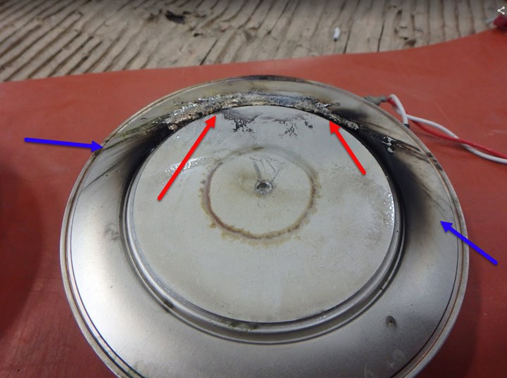
Figure 1: SCR damage due to uneven distribution of heat.
Photo Credit: All photos courtesy of Dynapower
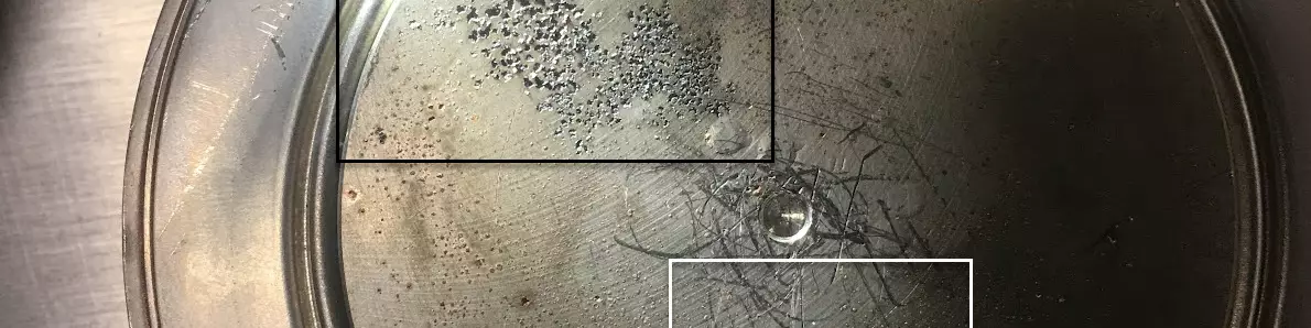
Figure 2 shows a black arrow pointing to a zone of pitting on the Diode. This area began welding onto the copper heatsink and the SCR was being depleted. The white zone on the picture indicates where the copper was welding onto the diode, and the copper was being depleted. Bizarre, right? What could have caused this slow weld? As a hint, the unit was fully operational when this was pulled off. Or rather, it was producing good product and all SCRs and Diodes were working — just until the machine overheated and turned off, then once it cooled down, it was able to resume operation.
The answer: The maintenance tech used improper mounting paste. The maintenance tech used heat sink paste that is thermally conductive, but does not pass electricity very well. Once the paste set and dried, there was a layer of resistance built between the conducting surfaces, and electricity began punching small welds through to make the contact more efficient. This further heated the entire device, gradually causing system overtemp faults.

Figure 2: Pitting on diode due to overheating.
Because the semiconductors do a majority of your work in the rectifier, you really need to take expert care of them. Keep them firing when they are supposed to, and keep them off at all other times. Make sure they receive adequate cooling, and that they are mounted evenly with even uniform pressure. And finally, most importantly, make sure the clamping pressure is exactly right. Each SCR has an engineered clamping force and size to have it run properly. Old clamps, especially those exposed to the metal finishing environment for too long, will lose tolerance and fall out of calibration. When the clamps are full of chemical and corroded, replace the clamps. You will be glad you did.
Power Components
Transformers, capacitors, and resistors can be some of the most interesting and scarily spectacular things to see fail. Hopefully, if you ever witness it, you are a safe distance away, already wearing sunglasses, and you don’t own the expensive asset that just went poof! We have had a rash of transformers and filters go bad in the last few years, mainly due to power fluctuations in the incoming power, and maintenance guys not knowing how to prevent excess heat being the other. These components need to be given a highly disciplined cleaning regiment. Just like the SCRs you should be focusing on making sure these stay cooled adequately, and you prioritize keeping these dry, clean, and free from foreign objects or contamination. Transformers make up a large portion of purchasing a new rectifier, and certainly if you are repairing one.
Too much heat on the windings can overcure the varnish and make it lose all of its insulating processes. Wet environments provide a path for transformer voltage leak to ground or phase to phase, bad news.
Dirty environments where that dirt, plating chemistry, and chip bags (this never happens, right?) are all stuffed into the transformer windings and need to be cleared. This can restrict airflow and cause the transformer to overheat, let alone be an arc path for electricity to go where it wants to. We want to make sure the transformer is not exposed to these bad things, or it can permanently compromise the integrity of the machine, causing you to need replacement years before its natural design life.
Figure 3 shows a transformer that witnessed a high-power fluctuation on the incoming side of the rectifier. Notice the carbon gets everywhere, and the replacement option may be the only option — repair may not be possible. In an arc flash, the carbon gets into the small, microscopic pores of whatever material it slams into (arc flashes can generate as much force as a 50 mph car crash) and permanently change the electrical properties of insulators the smoke hits. This is dangerous because something you previously depended on to hold electricity in, now is a probable path for the electricity to escape through. This means we need to be removing all the carbon and smoke from the material mechanically, which in turn means moving surface material from whatever the smoke hit. It’s a very destructive process. In arc flashes as large as these, this means enough material is compromised that the functional design on the windings, insulation and core of the transformer would be altered enough that they would no longer work as designed. Total loss.

Figure 3: This transformer witnessed a high-power fluctuation on the incoming side of the rectifier.
So how do we protect these transformers, capacitors, and relays? The major components that handle and transfer the power from base AC power at the wall to useable voltage at our tanks? We need to protect them from overheating! If we fire a semiconductor at the right time, only as designed, and into a load (parts at the tank) that is suitable for the rectifier, we do not overdrive those circuits. Over exerting those circuits creates massive amounts of heat. That heat is generated faster than the air or water (less dense materials) can transfer and remove the heat. And the component that is overheating has the possibility to melt even before a thermal circuit can register the heat.
The solution? Make sure your semiconductors and firing boards are well maintained and babied. They are the weakest link in the process and control how the power moves through the rest of the power components in the rectifier. Without them, the machine wouldn’t work. It’s similar to how without a human, an old school car wouldn’t drive (think 1980, not now with self-driving cars). But similarly, without a human, an old school car wouldn’t crash into a tree either. The regulator is the brain of the human, and the semiconductors are the hands and feet making the car move, working the controls and allowing the car to drive.
Oh, and obviously, don’t let your cooling loop or air channel get obstructed and stop heat removal from the process. It still amazes me how many times I need to remind people of that — the damage is permanent and the electrical devices change under that extreme heat, to where they never go back to working the same way again. Too many overheats? You have a really decorative, expensive, boat anchor.
Firing Boards
Firing boards are the brain of the operation. They are the weakest, least robust part, especially now that the circuit boards are using surface mount components and size has overall shrunk in the market over the years. Conformal coatings have changed to be more environmentally friendly and easier to apply, this can be challenging for a metal finishing environment because they can be more prone to dissolve in the presence of strong acids and bases. The one trick I like to teach my technicians is to use a blacklight. This picks up on smoke and residue that our eyes cannot see in dimly lit environments, and can show a density shift in conformal coating often caused by heat. This can be a game changer for predictive analysis.
If you are lucky enough to see the heat on the boards before something fails, you can save yourself a lot of money. Over the years the circuit boards give off substantial amounts of heat at power components like resistors and caps. This is as designed, but over seven to 10 years, can leave a pattern. Change the boards before you see discoloration affect components or the PCB fiberglass itself. Is the damage in Figure 4 due to a fault or prolonged use?
The answer is that the circuit board damage here can be from both an event, or from prolonged use. You need to be careful when making root cause determinations because initial results can be misleading.

Figure 4: Heat damage can occur from either an event or prolonged use.
The final indicator is seeing heat rapidly develop where it wasn’t there before. This can occur when a semiconductor or transformer is performing at a lesser state than designed, and this puts “pressure” on other parts of the system. Then, we notice the circuit board or small component damage, change the symptom, but not the root cause of the problem. The more experience you have learning these relationships, the better and easier time you will have in making a long-term fix that “sticks.” Figure 5 shows a circuit board small resistor that burns in the presence of a larger component failure in the unit. What do you think happened here?
This resistor on the circuit board burned due to too much current being run through it. This happened when a component on the back side of the machine experienced a short but continued to run in the circuit. The rectifier didn’t shut itself off as the component wasn’t a catastrophic failure…yet.

Figure 5: Damaged circuit board resistor due to too much current running through it.
In thinking about the long-term care of your critical DC power equipment, heat management is the number one root cause of failure. The bigger the amperage delivered, the more important heat management is to your process. Beyond the obvious of keeping the cooling channels free and clear, and making sure you are using the correct temperature cooling water/air across the cooling surfaces in the rectifier, small details like how components are mounted or tightened down can play a large impact to your success. Understanding the warning signs all around the machine and preventing catastrophic heat generation can save you thousands over the life cycle of your equipment. Being familiar with the warning signs can improve performance and prevent you from ultimately destroying your equipment.
RELATED CONTENT
-
The Many Hats of Rectifier Repair
Quick tips for improving the efficiency of rectifier maintenance.
-
A Smooth Transition from One Anodizing Process to Another
Knowing when to switch from chromic acid anodizing to thin film sulfuric acid anodizing is important. Learn about why the change should be considered and the challenges in doing so.
-
Defining a Top Shop: Quality, Quickness, Communication, Community
Luke Engineering & Anodizing Co. takes an active role in its community and the industry while also focusing heavily on the quality of its work and employee treatment.


