Evaluation of a Simple Thin-Film Ductility Tester and Review of the Ductility of Nickel Sulfamate Deposits
Originally published in 1992, this paper addressed a critical issue in the science of electroforming, that of the measurement and control of deposit ductility.
#research
Editor's Note: Originally published as G.A. DiBari, Plating and Surface Finishing, 79 (11), 60-66 (1992), this paper addressed a critical issue in the science of electroforming, that of the measurement and control of deposit ductility. At the time of publication, Dr. DiBari was employed by International Nickel, Inc. (Inco). A printable version of this paper can be accessed HERE.
ABSTRACT: Several years ago, apparatus devised by Nakahara, Okinaka and Turner, suitable for frequent determinations of the ductility of thin metallic films produced by electrodeposition and other processes,1 was replicated and used in an ASTM interlaboratory test program designed to determine the precision and accuracy of the method. The material used in the interlaboratory study was nickel deposited from sulfamate solutions. The ductility of nickel sulfamate electrodeposits, as determined by conventional uniaxial tensile testing, is reviewed and compared with the data gathered to assess the method.
Featured Content
Nickel electrodeposited from sulfamate solutions is widely used for electroforming. Because ductility is sensitive to impurities and to variations in internal stress, frequent determinations of ductility may help control the electroforming process and the mechanical properties of the electroform.
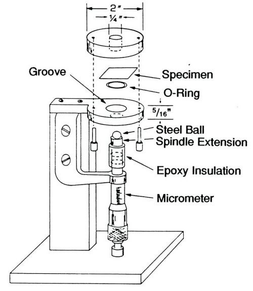
Figure 1 - Thin film ductility tester.
A drawing of the thin film ductility tester is shown in Fig. 1. The assembly consists of a stand to which are mounted a micrometer, a steel ball connected to a spindle electrically isolated from the micrometer, and a pair of circular plates, each with a round opening at the center. The test specimen is placed between the upper and lower plates, which are then firmly clamped together. The ball is then slowly raised by turning the micrometer handle. Initial contact of the ball with the metallic specimen completes an electrical circuit that causes a bulb in the upper plate to illuminate the specimen. The reading on the micrometer is recorded at this point.
By continuing to turn the micrometer, a bulge is mechanically formed in the metal specimen. The operator watches the formation of the bulge from start to finish with the help of the magnifier (not shown in the drawing). At the first sign of cracking, the operator stops and records the reading on the micrometer. The height of the bulge, determined by subtracting the initial from the final reading on the micrometer is a measure of the ductility of the foil. The height can be converted to percent elongation mathematically.
Replicates of the ductility tester were made in the Inco laboratory from prototype equipment and engineering drawings provided by Bell Laboratories, Murray Hill, N.J. These replicates were distributed to the participating laboratories.
The electrodeposited nickel foil was obtained from Inco Europe Ltd. and was prepared in a laboratory pilot production plant which makes foil continuously by deposition onto a rotating drum. The solution was the concentrated nickel sulfamate solution described in the literature.2 It contained 600 g/L nickel sulfamate, 10 g/L nickel chloride and 10 g/L boric acid. The process was operated at 70°C, at a current density of 50 A/dm2, and utilized S-Nickel pellets as the anode material in a conforming basket. The internal stress of the nickel deposited was maintained close to zero or slightly tensile. Different thicknesses of nickel foil were obtained by varying the speed of the rotating drum rather than by varying current density. This is similar to varying the time of plating and was done to maintain constant mechanical and physical properties of the nickel foil. The copper foil included in the study was commercially available.
The participants cut test specimens from the material with sharp scissors. The specimen size and shape are not critical, and can be about 3.5 × 3.5 cm. The maximum width of the specimen is 3.8 cm, which is the distance between the two clamping screws. Each of the participants made five measurements on nickel foil of four different thicknesses. In addition, measurements were made on annealed nickel foil and on the copper foil which was also annealed. The percent elongation of the nickel foil was also determined by standard uniaxial tensile testing.
The results were analyzed statistically by the procedure described in ASTM Standard E 691. The percent elongation values were calculated from the bulge height values by two formulas, one included in the paper by Nakahara and co-workers, and one suggested by Rolff.3
Estimate of precision
The statistical analysis was performed using the step-by-step procedure of ASTM Standard E 691 (Since this study was performed, software has become available designed to be used specifically with this ASTM Standard.). The results of the statistical treatment are given in Table 1. The average values of the within- and between-laboratory coefficients of variance are 7.89%. If the data obtained with material B are treated as outliers and excluded, the percent coefficients of variance become 7.08 and 5.68, respectively. The method appears capable of measuring ductility with a precision equal to or better than 10%. The overall precision given at the bottom of the table is about 9%, if the results with Material B are excluded.
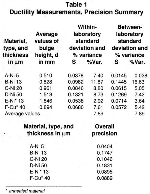
The standard deviations for Materials A, B, C and D are plotted vs. the average bulge height measurements in Fig. 2. If the measurements made on Material B are disregarded, the data in the figure suggest that the standard deviations increase as the ductility and the thickness of the nickel increases. The data indicate that the ductility tester is best suited for measurements on thin films, a point emphasized in the paper by Okinaka and co-workers. The limiting thickness is about 50 μm.
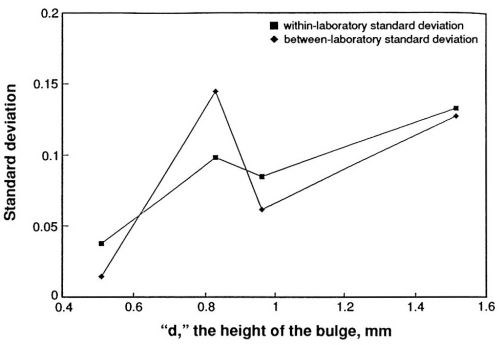
Figure 2 - Ductility of nickel; within- and between-laboratory variability.
Calculation of percent elongation
Percent elongation has been calculated by means of the formulas mentioned previously. The relationship between the bulge height and percent elongation calculated from the two formulas is shown in Fig. 3. The Rolff formula gives higher values than the Nakahara formula below about 7% elongation and lower ones above that value. The Nakahara formula is simpler and has been applied in a commercial model that provides direct read-out of percent elongation. The simple formula will be included in the ASTM Standard Test Method that is in preparation. The formulas are given in the appendix.
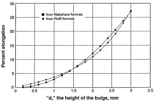
Figure 3 - Relationship between bulge height and percent ductility calculated from two formulas.
Ductility of nickel sulfamate deposits
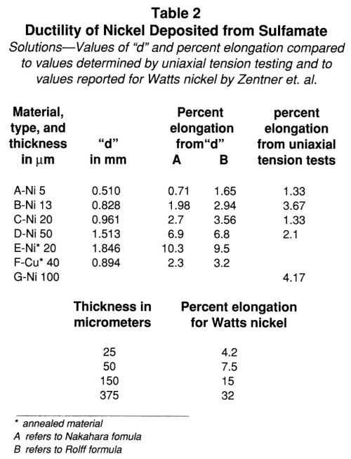
The height of the bulge is indicative of the ductility of the metallic film and is plotted vs. the thickness in Fig. 4. Ductility apparently increases as the thickness of nickel increases. The ductility of the annealed nickel deposit is greater than that of the as-deposited material, as indicated by the bulge height data included in Table 1. It is necessary to express ductility as percent elongation to compare results obtained by different methods and to obtain some idea of the accuracy of the method. These values are compiled in Table 2. The percent elongation of the as-deposited nickel sulfamate foils varied from 0.7 to about 7.0% as the thickness increased. The differences in the values calculated by the two formulas are evident.
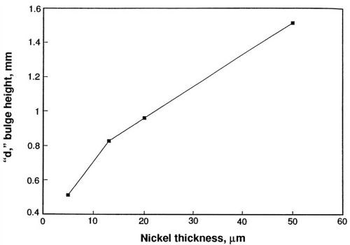
Figure 4 - Ductility of nickel deposited from sulfamate solutions as a function of nickel thickness.
In Fig. 5, the percent elongations calculated from the bulge height data are plotted beside data reported by Zentner and co-workers for the percent elongation of Watts nickel deposits.4 The data suggest that the ductility of electrodeposited nickel increases over a broad range of nickel thicknesses. The fact that the data obtained in this study overlap the data for Watts nickel and are almost a smooth extrapolation of it suggests two things: (1) The thin film ductility tester is accurate, and (2) the ductility of Watts and sulfamate nickel deposits may be similar at thicknesses below 50 μm.
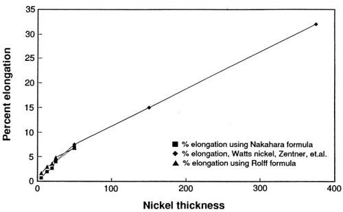
Figure 5 - Nickel ductility as a function of thickness; comparison with values reported by Zentner.
The ductility of the nickel sulfamate deposits as measured in the thin film ductility tester and by standard uniaxial tension testing is compared in Fig. 6. The differences are apparent. Above 20 μm, the percent ductility is lower when measured by tensile testing than by bulge testing. Note that the unusually high value of ductility at 13 μm in uniaxial testing was obtained with Material B and supports the earlier decision to treat the results with Material B as outliers.
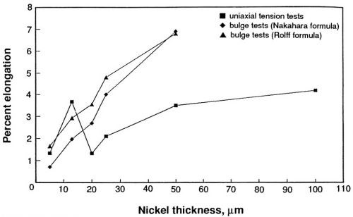
Figure 6- Ductility of nickel sulfamate deposits; comparison of uniaxial tension test results with bulge test results.
To confirm further that the variation in percent elongation with thickness is not an artifact of the test method and is not related to the type of electroformed nickel used in the interlaboratory study, it is of interest to review the results of a study done in the Inco laboratory a number of years ago (Chart, 1977). In this study, the material was produced from a conventional nickel sulfamate solution and mechanical properties were determined by uniaxial tension testing. The study was designed to determine the effect of thickness, as well as variations in internal stress which occur when small insoluble auxiliary anodes are used with primary anodes for plating from sulfamate solutions.
Nickel sulfamate deposits with tensile internal stress were obtained from conventional solutions; the stress was stable at 50 MPa (the solution contained 70 g/L of nickel metal as the sulfamate, 0.1 g/L of chloride added as nickel chloride hexahydrate, and 35 g/L boric acid. The pH was 4.0, temperature 60°C, and cathode current density 540 A/m2. The bath was operated with air agitation. After tensively stressed deposits were prepared over a range of thicknesses, similar compressively stressed deposits were prepared by including a platinum foil anode in the circuit and passing one to two percent of the total current through the auxiliary anode. The current density on the auxiliary anode was 2.7 A/m2. This procedure gave deposits with an internal stress of 71 MPa, in compression.
The effects on the ultimate tensile strength, and the percent elongation of nickel electroformed under these conditions, are shown in Figs. 7 and 8. The ultimate tensile strength varies with nickel thickness but becomes stable above 250 μm (Fig. 7). The strength of the compressively stressed deposits is greater than that of the tensively stressed deposits. Annealing at 371°C for two hours lowers the tensile strength of both types of deposits to approximately equal values. Annealing at the higher temperature (760°C) lowers the tensile strength even further, but the decrease is significantly greater in the case of the compressively stressed deposits.
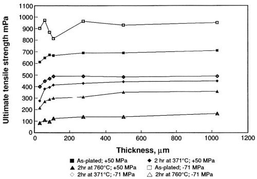
Figure 7 - Effect of sulfur on the ultimate tensile strength of sulfamate nickel.
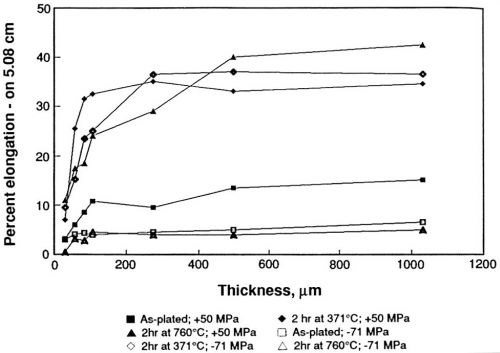
Figure 8 - Effect of sulfur on the percent elongation of sulfamate nickel.
The ductility shows greater variation with thickness than does the ultimate tensile strength, Fig. 8. Ductility is greater for the tensively stressed deposits than for compressive deposits in the as-plated condition. Annealing at 371°C increases the ductility of both types of deposits. Annealing at 760°C increases the ductility of the tensively stressed deposits but lowers the ductility of compressively stressed deposits to values below those as-plated. The deposits were also analyzed chemically. The tensively stressed deposits contained less than one ppm sulfur, whereas the compressive deposits contained about 40 ppm. Metallographic and electron microprobe analyses conducted after annealing showed brittle failure in compressive deposits heated at 760°C, as well as high sulfur (380 to 500 ppm) contents in grain boundaries.
The study established that the oxidation products formed at an insoluble platinum anode in sulfamate solutions lower internal stress and result in the codeposition of sulfur. Codeposition of small amounts of sulfur affects the mechanical properties of electroformed nickel, especially at high temperature. Although the strength and ductility become relatively constant above 250 μm thickness, the percent elongation shows great variation below about 100 μm. The variation of percent elongation with thickness shown in Fig. 8 is similar to the variation shown in Fig. 6, which supports the observation that the simple mechanical bulge tester is accurate, as well as precise. The values determined uniaxially are again lower than those determined biaxially.
Summary
The thin film ductility tester devised by Nakahara, Okinaka and Turner is a reliable instrument for measuring the ductility of metallic films. The precision is better than 10%. The variation of the standard deviations with ductility and deposit thickness suggest that this particular instrument is best suited for measurements on deposits that are less than 50 μm thick. Since this study, a commercial model became available which provides a direct read-out of percent elongation.3
The study also confirmed that the ductility of nickel deposited from sulfamate solutions increases as the thickness of the nickel increases. This is similar to the behavior of nickel deposited from Watts solutions, as reported by Zentner and coworkers many years ago. The ductility of nickel deposited from Watts and sulfamate solutions may have similar values at thicknesses below 50 μm. The calculation of percent elongation from the bulge height, using two different expressions, results in different values. Measurements made on identical materials by uniaxial tension testing gave lower ductility values than those made with the thin film ductility tester, in most cases. A comparison of percent elongation values determined by uniaxial tension testing and by mechanical bulge testing confirmed that the variation of ductility with nickel thickness is not an artifact and is observed in sulfamate nickel deposits prepared under different conditions. The properties of sulfamate nickel deposits may be influenced by uncontrolled anode behavior, as simulated by the use of a small auxiliary platinum anode. Frequent determinations of percent elongation by the mechanical bulge tester may aid process control and is encouraged.
The mechanical bulge tester has been used to study the properties of copper in printed circuit board applications.5
Acknowledgments
The assistance of the following active and retired members of ASTM Committee B-8 is greatly appreciated: Mr. R.J. Clauss, OMI International; Dr. E.J. Seyb, M&T Chemicals Inc.; Mr. J.K. Long, Harshaw Chemical Company; Mr. F. Ogburn, National Institute of Standards and Testing; Mr. G.A. Laitinen and Mr. J. Horner, Allied-Kelite Corporation; Dr. G.L Fisher and Mr. G. Hawks, formerly with Inco.
References
1. S. Nakahara, Y. Okinaka, and D. Turner, "A Simple Ductility Tester for Metal Films," Journal of Testing and Evaluation, 5 (3), 177-182 (1977); https://doi.org/10.1520/JTE11635J
2. R.K. Kendrick, Trans. IMF, 42, 235, (1964).
3. R. Rolff, "Significance of Ductility and New Methods of Measuring Same"; ASTM Special Technical Publication 947, Testing of Metallic and Inorganic Coatings, W.B. Harding and G.A. DiBari, eds. p. 19 (1987). Alternate methods of measuring ductility, such as hydraulic bulge testing, are discussed in several of the papers included in this publication.
4. V. Zentner, A. Brenner and C.W. Jennings, AES Research Report No. 20, "Physical Properties of Electrodeposited Metals—Nickel" (1952).
5. G.L. Fisher, O.B. Dutkewych and D.E. Storjohann, P.C. Fab., 9, 92, (Oct., 1986) and 64 (Nov., 1986).
About the author (at the time of original publication)

Dr. George A. DiBari is manager, Plating Products - International at International Nickel Inc. (INCO), Park 80 West - Plaza Two, Saddle Brook, NJ 07662. He has been with Inco for 30 years in various capacities, including R&D and marketing. He is a co-inventor of S-Nickel and a co-developer of S-Rounds and R-Rounds electrolytic nickel. He holds degrees in chemistry from Brooklyn College and the Polytechnic Institute of New York, and a Ph.D. in metallurgy from the Pennsylvania State University. He is a long-time member of AESF and past chairman of the AESF Research Board. In 1987, he received the Frederick Lowenheim Memorial Award from ASTM Committee B8. [In 1998, he was named the recipient of the AESF William Blum Scientific Achievement Award.]
RELATED CONTENT
-
Cyanide Destruction: A New Look at an Age-Old Problem
Cyanide in mining and industrial wastewaters has been around from the beginning, including electroplating processes. This presentation reviews a number of current processes, and in particular, offers new technologies for improvement in cyanide destruction by the most common process, using sodium hypochlorite.
-
White Bronze, Copper-Tin-Zinc Tri-metal: Expanding Applications and New Developments in a Changing Landscape
This paper deals with the renewed interest in applications for white bronze tri-metal (Cu-Sn-Zn alloy).
-
Chromium-free Etching and Palladium-free Plating of Plastics
Plastics are replacing metals in the manufacture of many parts, and quite often there is a need for metallic coatings on the plastics and other non-conductors. This paper will describe new processes of preparing ABS plastic substrates for subsequent metallization.


