Things to Know About Cam Grinding
By James Gaffney, Product Engineer, Precision Grinding and Patrick D. Redington, Manager, Precision Grinding Business Unit, Norton Company (Worcester, MA)
The changing shape and composition of camshafts are challenging those responsible for surface finishing. As a result, an increasing number of cam-grinding operations are being performed with cubic boron nitride (CBN) superabrasives and technologically advanced conventional abrasives.
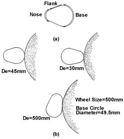
Camshaft grinding requires instantaneous changes in wheel-work contact length and material removal rates. In camshaft grinding, the arc of the contact between the wheel and the camlobe changes continuously as the base circle, flanks and nose are ground (seeillustration). The arc of contact can be represented by means of the equivalent diameter (De) and can be calculated:
Featured Content
|
with: Ds is the wheel diameter |
A large equivalent diameter represents a longer arc of contact between the wheel and work material. So the arc of contact is large as the wheel passes over the flanks and becomes smaller as the nose and base circle are ground.
As the De increases, more abrasive particles come in contact with the work material. This reduces the force acting on each grain, and makes the ploughing and sliding interactions more dominant. This is usually observed as increased grinding power or force for the same grinding condition.
In camshaft grinding, as the De is larger while grinding the flanks, higher power will result if the radial infeed and work speeds are maintained the same as when grinding the nose or base circle. This can result in unacceptable thermal damage on the lobes. In order to avoid this problem, the work speed is generally reduced as the wheel grinds the flank portions. This reduces the rate of material removal and helps lower the grinding power.
Take Care
Camlobe grinding is a complex variant of cylindrical grinding. When raw camshafts are manufactured—by casting in sand or shell molds (cast iron), forged or machined from barstock (steel)—roughly 0.02 to 0.12 in. of stock is generally available for grinding. After the lobes and journals are induction hardened, the journal bearings are ground, usually on a centerless or cylindrical grinder. Since the camshaft is supported on workrests, with the journals as a reference during camlobe grinding, it is important that the journals be ground properly because any imperfections will be translated to the camlobes during lobe grinding.
Although the necessary surface finish on the lobes and journals is usually provided by the grinding, they are often lapped with fine-grit abrasive belts. Lapping after grinding has been found to be effective in reducing initial friction during the engine break-in period.
New Profiles
During the past decade, camlobes with a re-entrant profile have been gaining popularity because this design helps increase engine torque and horsepower and reduces emissions. In re-entrant camlobes, the ramps are concave instead of a straight line; this helps in opening and closing the valves much faster.
Also, the use of roller bearings at the interface with the camshaft in place of flat tappets has reduced friction, permitting higher engine speeds. However, the sharp line contact results in significant increases in contact stresses, which can exceed 250,000 psi. These high stresses can result in spalling and accelerated camlobe wear. So depending on the magnitude of the contact stresses, camshafts of different construction are used.
For lower contact stress applications, induction hardened or chilled nodular cast iron may be acceptable.
For contact stresses of 250,000 psi and above, steel cams can provide the most-reliable solution.
Composite Approaches
Composite camshafts of medium- and high-alloyed powered metal lobes mounted on a hollow tube are popular as they have the capacity of withstanding high contact stresses and offer improved tribological properties. Composite camshafts can be 50% lighter than cast iron or steel shafts; can have lobe material tailored to the application; and they can have lobes molded to near-net shape, which means that the amount of grinding stock, and consequently grinding time, are both reduced.
The requirements to have high-strength, low friction and minimal wear have prompted Japanese researchers to consider ceramic camlobes.
Camlobes are usually machined to final shape by grinding with bonded abrasive wheels containing aluminum oxide or CBN. Usually, one lobe is ground at a time, although in order to improve productivity, machines using multiple abrasive wheels are available. With this equipment, two wheels are mounted on a one-piece precision-balanced hub to grind two lobes at a time. But this approach can be used only if the lobes being ground simultaneously have similar lift profiles.
Abrasive Belts
Another approach to improve cycle time is using machines with abrasive belts. This was developed in Italy in 1977; it was successfully implemented by GM engineers only in the early 1990s. In these machines, the abrasive belt is pressed against the workpiece by a cylindrical contact shoe that, together with the belt, replaces the curved surface of the grinding wheel. These multiple-belt cam grinding machines can grind all lobes simultaneously for cycle time reduction.
Another advantage offered by these machines is in the grinding of re-entrant camlobes. Grinding of re-entry type cam profiles with grinding wheel requires that smaller diameter wheels be used. This restricts the life of the wheel, making its use less cost-effective. With abrasive belts, the curvature of the belt can be controlled by changing the contact shoe diameter, so re-entry lobes of high negative curvature can be easily ground.
Higher Speeds
The current trend to reduce cycle time involves grinding at high wheels speeds. Machine builders in Europe and Japan are marketing high-speed cam-grinding machines with wheel speed capability of up to 200 m/sec. High grinding wheel speeds offer the advantage of longer wheel life, lower forces, and high removal rates. Higher metal removal rates at higher wheel speeds reduce cycle time.
A variation of the high-speed approach involves high wheel speeds, large depth of cuts, and low work speeds. This approach is similar to High Efficiency Deep Grinding (HEDG) and is essentially high-speed, cylindrical, creep-feed grinding.
Another approach uses a high-speed grinder with a pair of wheel heads. One wheel head uses a brazed, single-layer CBN wheel and is used to rough grind the lobes very aggressively. The other wheel head uses a small-diameter vitrified CBN wheel for finishing the lobes. This approach has been successfully used to grind re-entry type camlobes.
Vitrified bonded aluminum oxide wheels are still popular for grinding camshafts, but most CNC machines are now shipped with superabrasive wheels.
CBN & Beyond
The hardness, thermal conductivity and chemical inertness of CBN
have made it an abrasive of choice for production grinding of ferrous and aerospace alloys. Several bond systems—resin, metal, glass, and brazed—are available with CBN. Among these, the glass, or vitrified, bond system has proven to be the most popular. These bonds are rigid, free-cutting and have good form-retention. In addition, the porosity in these bonds can be controlled for more chip clearance and better coolant application at the grinding zone. Vitrified bonded wheels are easy to true and do not require additional dressing procedures.
The inherent brittleness of the vitrified bond system contributes to the self-sharpening action during grinding, but the brittleness also makes the wheels susceptible to chipping and breaking if used improperly.
One answer to this problem is a segmented wheel design, where individual segments are cemented to a steel or aluminum oxide core. Benefits include:
•Easy replacement of damaged sections
•Safety at high wheels speeds—up to 150 to 200 m/sec.
•Properties of individual segments can be measured and monitored so there is consistency along the wheel periphery and from wheel to wheel.
•Special wheel adapters can be resegmented and reused after the CBN layer has worn out.
There is also a ceramic aluminum oxide abrasive that's making an impact in cylindrical grinding operations. This elongated, high-aspect ratio abrasive can make a difference in high speed grinding of cast-iron camlobes. They provide high removal rates compared to a vitrified CBN wheel. The lower cost and single-point truing capability compared to CBN could make them excellent alternatives.
RELATED CONTENT
-
What is Electrocoating?
E-coat can produce uniform finishes with excellent coverage and outstanding corrosion resistance.
-
Aluminum Surface Finishing Corrosion Causes and Troubleshooting
In this paper, a review of several process solutions, examining coolants, solvent cleaning, alkaline clean/etch and deoxidizing/desmutting, listing intended and unintended chemical reactions along with possible mechanisms that would favor corrosion formation.
-
Pretreatment for Painting
Better adhesion, enhanced corrosion and blister resistance, and reduced coating-part interactions make pretreatment a must.


