Fifth Generation Reduced Ion Electroless Nickel Systems
Through R&D efforts over the last decade, EN technology suppliers have demonstrated many advances toward replacing lead and cadmium as stabilizing and brightening systems in 50-year-old nickel phosphorus alloy technology.
Since year 2002, various legislative drivers have fueled the evolution of Electroless Nickel (EN) technology. Through Research and Development (R&D) efforts over the next decade, EN technology suppliers demonstrated many advances toward replacing lead and cadmium as stabilizing and brightening systems in 50 year old Nickel Phosphorus alloy technology that over these prior decades were successfully utilized for automotive, aerospace, electronics and industrial applications. A historic evolution time-line by generation is shown in figure 1. From our perspective, the evolution phase of Electroless Nickel development today exists as a 5th generation which is offering some exciting results for applicators.
Featured Content
The commercial results of EN systems from the 4th generation developed platforms have demonstrated good success. There are numerous examples where EN Environmentally Friendly (EF) technologies today out-perform their predecessor lead stabilized systems. This generation of systems developed has been a “win” for our industry but challenges still exist that offer opportunity for continued development.
From an R&D & formulation perspective, new knowledge gained during the development work replacing lead stabilizing systems of the 4th generation (4G) EF EN systems opened the door to new opportunity to think about EN formulations differently. New “additives”, those critical species for EN chemistries including metallic, non-metallic or organic chemical species have been discovered and are being utilized today. Their uses are shown to provide overall improved solution stability, enhanced deposition rates but more importantly the discovery that with their use allows the 4G EN system platform to experience a new range of operating conditions and allow basic chemistry variations that result in greater extended performance which is what applicators expect from systems they utilize today.
However, as an industry, the need for continued evolution with EN technology is in demand because there remains much volatility in the market. Still today, continued regulatory demands pending for nickel and burdens felt as a result of the REACh initiative continue to push EN chemistry providers into reactive mode. These demands are also stretching applicators ability to maintain profitability in an environment where operating costs continue to increase. Applicators “feel the pain” as regulations make it more difficult for maintaining business sustainability and profitability, an important recognized driver for business. It does not appear that regulations will go away anytime soon. Squeezing profitability impacts everyone across the EN supply chain in our industry but is a driver for directing the next evolution development. Continued regulatory turmoil causes well-known companies including suppliers and applicators to consolidate, long time industry publications to cease operation, and companies who once recycled EN solutions to get out of that business, all actions that further disrupt industry and impact cost and profit structures. As a result, it makes sense that applicators are searching for increased value at lower cost. So what is available today for EN applicators looking to improvement the management of their processing costs without redesigning their existing operations, modifying or adding a piece of equipment for their EN department?
Coventya's Brad Durkin on 5G EN Systems
Evolution of Fifth Generation (5G) Reduced Ion Development:
EN formulation basics are well defined in our industry through patents and prior art or knowledge in various teachings and publications. One commonly accepted mechanism for the reduction and deposition of nickel in a hypophosphite reduced bath is as follows:
1. NiSO4 + H2O → Ni++ + SO4 = + H2O
2. NaH2PO2 + H2O → Na+ + H2PO2- + H2O
3. Ni++ + H2PO2- + H2O → Nio + H2PO3- + 2H+
4. H2PO2- + H2O → H2PO3- + H2↑
Equations (1) and (2) simply show the dissociation of the nickel salt and sodium hypophosphite in water. Sulfate and sodium are the by-products of these two reactions that build up with usage. Equation (3) shows the reduction of the nickel ion by hypophosphite to form nickel metal on the parts and an orthophosphite anion which is another major by-product. Equation (4) shows a parallel reaction of hypophosphite with water to form orthophosphite and hydrogen gas.
In these reactions, from the by-products produced perspective provides a clear understanding of what limits EN solution MTO potential. For every 1 g of nickel metal plated, 3.9 g of orthophosphite ion (5.0 g as sodium orthophosphite), 1.64 g of sulfate, and 1.1 g of sodium are produced, and remain in the plating bath as the solution ages. The build-up of these major by-products and salts over the course of the bath life is the primary reason EN is a self-limiting process. This increase, specifically of sodium orthophosphite and sodium sulfate including some other anions, increases the density of the solution at a rapid rate that eventually causes a further degradation in the solubility of other components, which often tend to be the “additives” and stabilizing species which are most critical for sustainability of the EN reactions.
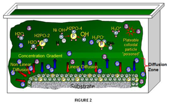
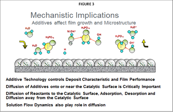
As noted, the primary difference impacting plating performance between nickel phosphorus EN systems results from the “additives” being utilized. The selection of ”additives” representing many types of chemical species are the secrets utilized by EN suppliers for enhancing EN performance and operation, often used in mg/L concentration ranges. The primary functionality for these additives in any EN chemistry is to control solution diffusion efficiencies that take place at the part (substrate) EN solution interface when the applicator places parts into the EN tank. Figure 2 represents a graphical illustration of these solution interactions. As Nickel plating continues in this diffusion zone, the Ni-P alloy builds layers upon itself for providing the final deposit thickness. Additives are known to be very critical and selective for establishing the proper equilibrium for the EN chemical reactions to take place in this diffusion zone as illustrated in figure 3.
The total electrolyte concentration in solution will affect important chemical species properties such as the dissociation or solubility of different salts which also impacts how the system “additives” respond. Suppliers formulate different balances of these chemistry constituents to make the commercial EN systems purchased by applicators for producing NiP alloy deposits.
Other than the “additives” chosen, from a strictly technology perspective, all commercial EN systems today have many chemistry constituents in common including a source of nickel, a reducing agent, traditionally sodium hypophosphite, various blends or strength of chelation species and buffer chemistry. All EN systems have a given ionic strength when in the applicators tank. The ionic strength of an EN solution is a measure of the concentration of ions in that solution which changes over each metal turnover (MTO).
As EN solutions are used, ionic strength concentration changes impact solubility which is important to understand when designing new “additives”. As an EN supplier, focusing on ionic strength interactions, we have improved our understanding how the selection and choice of additives impact EN performance and resulting deposit quality for the applicator.
The assumptions from the Debye-Hückel Theory of Electrolytes help to understand these interactions in ionic solutions. The properties of electrolyte solutions can significantly deviate from the laws used to derive chemical potential of solutions. The basic principle in ionic solutions, there are significant ionic and electrostatic interactions between solute-solvent as well as solute-solute molecules which allow for more dissolution because only free ions enter into the expression for the solubility product equilibrium constant. From a simple mathematical point of view, in higher ionic strength solutions, activity coefficients of key chemical species become smaller, and hence their concentrations must be greater to maintain a constant solubility product at equilibrium.
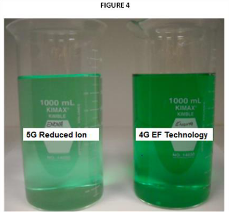
Over the past two years, extensive R&D work on improving our understanding toward the interaction and role of ionic strength of EN solutions, common ion effect and the role that plays toward solubility of the critical additives and stabilizer species helped direct new development efforts. In high ionic strength complex mixtures, working with the theory and practical understanding of activity versus concentration in these EN chemistry interactions resulted in the development of new organic and inorganic additive species that have resulted in improved EN solution performance. Providing new “additives” that have demonstrated improved solubility in these complex mixtures helps to provide longer solution life which also corresponds to more surface areas to be processed but our overall understanding with these interactions helped to derive a new range of additives that are more efficient in the chemistry reactions of EN solutions which resulted in the 5G reduced-ion (RI) technology. (Figure 4).
How Can The Applicator Benefit?
Driving businesses today are requirements for improved quality, better business or environmental sustainability, a long term mindset where ecology and economy are merged, but none of that matters unless business is focused on some improvement or maintaining profitability. The 5G reduced ion technologies have demonstrated savings for applicators in two primary areas of concern. These systems can provide an improved EN technology platform toward achieving a higher level of environmental conformance while also providing lower total operating costs without risk or compromise to the traditional deposit engineering properties established for conventional EN NiP alloy systems.
As shown in figure 5, there are systems with primary attributes designed for providing deposits ranging from medium Ni-P alloy systems to high Ni-P alloy systems.
From an applicator perspective, how well any given EN chemistry operates in the tank is known to impact the total profit snapshot. Production throughput elements including, deposition rates, down time for tank transfer or shortened EN MTO solution life or solution maintenance costs are important variables. From a deposit quality perspective, rejects increase cost from a rework cycle that can include stripping the original plating, and costs associated with the stripping process, loss of valuable production time from replating the part detract overall from applicator profit so capturing any savings is of benefit to the applicator.
As an applicator, if you experience increased potential or higher incidence rates for EN solution plate-out in your EN operation which requires increased down-time and more exposure of workforce to hazardous stripping chemistry, then Eco-optimized reduced ion chemistry can make your operation more profitable while improving efficiency. The cost of waste treatment will likely not get less expensive and managing these costs will only become more difficult in the future so knowing what alternatives exist can be critical to your business.
Also, the reduced ion chemistry platform offers other benefits including long solution life through increased MTO’s especially important plating EN over aluminum substrates without the need for adding an additional alkaline EN strike tank to the process line, EN deposits that include color options and higher speed systems designed for increased production throughput.
In production examples, with 5G reduced ion technology, applicators find they can plate aluminum well past 12 MTO’s (equivalent 6 MTO’s or 36 g/L nickel deposited) without fear of blisters or poor adhesion. Up until now, this type of long life achievement over aluminum is commonly unheard of without the requirement for incorporating a separate alkaline EN strike into the process line which is not required which add to overall chemistry and process savings.
Roughly 50 to 65% of a standard EN system chemistry cost is directly related to the price of nickel metal and sodium hypophosphite. Given this impact, sodium hypophosphite efficiency can be affected by the types of additives used and their concentration especially in the diffusion zone of plating. As a reference guide for 4G EN systems, typically for hypophosphite reduced high phosphorus (10–13 percent) baths, the efficiency is 5.6 g of hypo consumed for every 1 g of nickel deposited. For medium phosphorus (7–9 percent) baths, 5 g of hypo are consumed for every 1 g of nickel. For the low-medium phosphorus (4–6 percent) systems, 4.2 g of hypo are consumed for every 1 g of nickel deposited. Experience with 5G EN technology demonstrates up to 20% improvement in hypo efficiency resulting from the reduced overall solution ionic strength and selection of additives utilized in a given EN formulation. As many consumers target high fuel efficiency for their vehicles today, why shouldn’t EN applicators expect to maximize efficiencies obtained from the technologies they utilize? For the 5G reduced ion EN technology, maximizing efficiencies was an important design criteria through the careful development and selection of “additives” for these systems.
From an environmental perspective, reduced exposure to nickel in rinse waters, in spent EN process solutions, in EN air emissions is becoming a higher emphasis point for creating a safer work environment which is an important regulatory initiative. In December 2010, a European rule was also implemented, specifically the 30th – 31st ATP classification, CLP 00/ATP 01, which rules Nickel as toxic and provides danger to health by prolonged exposure through inhalation which heightens the need to look at ways to reduce nickel exposure wherever possible. This regulation does not today directly impact business in the USA metal finishing sector, however utilizing reduced ion EN technology provides applicators the ability to improve their environmental “footprint” of responsibility without any negative drain on profitability.
One element of reduced ion EN chemistry allows the development of EN systems that can be operated at much lower nickel concentrations than traditional EF systems without compromising tank processing performance as early 4G EN systems experienced. Being able to extend EN solution life without adding extra equipment to increase cost or forcing applicators to move away from well-defined and trusted nickel sulfate chemistry technology for alternative types with the potential of a new learning curve can be avoided. This initiative ideally suits Eco-optimized reduced ion technology which is a drop in replacement to your existing process line.
Cost savings Eco-optimized 5G Reduced Ion EN technologies add up for the applicator.
There are initial savings with each new solution tank make up, specifically dependent upon the price of your nickel sulfate make up concentrate. The realized savings range just for the contribution of the nickel ranges from 8 to 12% if the system is being operated at a 3 g/L Ni concentration. For the 5G lower metal systems there are a range from 8 to 15% longer solution life compared to 4G conventional mid phosphorus chemistry. Today for a conventional mid phosphorus, 6 g/L EN system, under average operating conditions, typical solution life expectation is 50 to 60 grams/L of nickel deposited per bath life which corresponds to 8 – 10 metal turnovers (MTO). For the 5G system, given the same work load and Ni-P thickness requirements, there are 66 to 70 grams/L of nickel deposited per bath life which corresponds to an equivalent 11 to 12 MTO’s on a 6 g/L Ni per MTO basis. This result occurs from the benefits gained with the new development of additives utilized in the 5G reduced ionic strength chemistry. Also, the reduced ion chemistry compensates for the dissolved solids build up per gram nickel deposited during plating which contributes to improved life. Additionally, production experience with this technology provides there are less incidents of tank solution plate-out or extraneous plating on equipment which directly correlates to a reduced cost of operation.
To better put the EN chemistry savings into perspective, a high production EN applicator might make up 45 or more EN chemistry tanks annually, and by extending the replenishment life from 8 to 15% more MTO’s provides for several areas of saving. As a result extending the replenishment life, the applicator makes up less EN baths in a given year. Money is saved on the EN solution make-up cost for 3 to 7 EN tanks annually in this example. Specifically for each 100 gallon EN tank volume, these make-ups contribute 6 gallons/100 gal of nickel cost and the “B” hypo make up component which is typically utilized at 15% v/v or 15 gallons for each 100 gallons of solution tank volume. Since EN make up cost for standard 6 g/L chemistry typically ranges from $3.00 to $4.00/gal, savings can add up quickly especially for larger volume tanks. Additionally, the longer life extension for each new EN make-up solution that is saved, in this example, from 3 to 7 EN solutions annually which also reduces a total of 300 to 700 gallons of EN solution waste (for each 100 gallon tank volume amount) going to disposal or recycle all at some associated cost. Also, the costs for the applicator associated with any lost production time (down time) and associated labor costs or shop costs from making up a new EN and the time required for stripping tanks are important to consider. And for larger production tanks & facilities, the cost savings as a multiple can become more significant.
Overall, with 5G reduced ion operations, there is less nickel in the solution drag-out vs a 6 g/L conventional technology which can reduce the overall in-house treatment costs by reducing the amount of treatment chemistry (NaOH, polymers, etc.) required for the treatment.
Many detailed comparative laboratory studies confirm what applicators experience, less nickel in their waste streams as shown in Figure 6. In this study, steel hull cell panels are plated in each respective 2 liter EN solution. At the conclusion of plating, the panels are removed and held above the EN solution for a standard dwell time of 5 seconds. Next, the panels are transferred to a dead deionized (DI) water rinse for 2 minutes. Fresh DI water is sprayed over the steel surface to ensure all Ni+2 ions are collected. After 5 consecutive panels are processed for each EN solution, equating to 1 MTO, all the rinse water is transferred to a 2 liter volumetric flask where the final volumes are standardized by proper dilution. Nickel metal is analyzed for each sample by Atomic Absorption. As the results show, there is a 75% reduction in the loss of nickel to the rinses by utilizing a 5G reduced ion system. In other tests, results range from a 50% to 75% reduction in the amount of nickel lost through solution drag-out.
Now on the waste side of the EN operation, once the solution has reached its useful life (the MTO limit), applicators today either treat the EN waste in-house or have the EN waste solution hauled away for recycling. For in-house treatment, the fact that the 5G Reduced Ion allows reduced processing time regardless of the method utilized for meeting a final mg/L nickel limit offers improved efficiency and resulting total cost. Specific toward recycling or haul-away for treatment, another benefit from the 5G reduced ion technology allows the spent EN waste solution to be concentrated through evaporation of water. Experience shows that spent 5G reduced ion solutions can be easily evaporated to 50%-60% of original waste volume. Standard 4G EF spent EN chemistry can only be evaporated to 20% - 30% because total dissolved solids are much higher and the waste spent solution will precipitate if more water is removed. This advantage with ability to evaporate is cost advantageous since the total volume of waste being transported off site is less which impacts treatment cost but more importantly the cost of haul-away transportation which is often based on weight or total volume. In either case, experience shows that more 5G reduced ion waste volume can be processed compared to a standard 4G EN Ni-P chemistry. A summary of cost savings can be viewed in Figure 7.
We tried lower metal EN systems many years ago and our experience was poor, why would 5G reduced ion EN technology perform differently?
Specific for early low metal operating systems, typically < 4 g/L Nickel operating systems, the first commercial production systems developed during the past decade demonstrated performance deficiencies compared to conventional 6 g/L Ni 4th generation technology counterparts. That is one reason why these systems were not widely accepted in the past. Despite their lower metal advantages in the waste stream and less nickel in the spent EN chemistry, applicators did not embrace the slower deposition rates, shorter MTO life resulting from sensitivity to trace amounts of contamination, or the narrower operating window these systems provided. Additionally there was no total cost advantage because operating efficiencies were not improved. Overall, the total operating cost of these early lower metal alternative approaches ended up being higher than conventional 6 g/L chemistry which off-set any significant cost savings realized on the waste treatment side. The ideas of low metal operation existed in principle but the practical side did not match up to market expectations.
Fast forward today, with the 5G Reduced Ion chemistry developments, we are finally experiencing advantages for applicators operating at 3 – 4 g/L nickel metal concentration. Applicators report gains up to 15 - 20% longer solution life versus the standard EN technology which has an immediate impact of less total number of solution make-ups annually which can be a significant cost savings.
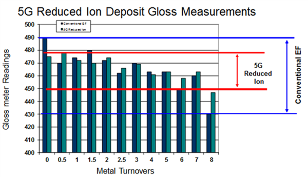
From a deposit quality perspective, the 5G reduced ion systems provide more consistent deposit color and brightness appearance as deposit gloss measurements are shown in Figure 8. Additionally we see corresponding improved deposit smoothness over the increased MTO solution life which is not common for many 4G conventional EN systems.
With 4G EF systems, plating high strength steel, brass or copper substrates always provided some challenges with slow or no initiation areas which is much improved with 5G reduced ion technology. There is no need to utilize special activators or electrolytic activation in the EN solution as experienced with 4G conventional EN technology.
As shown in figure 9, the resulting deposition rates from eco-optimized reduced ion EN systems are equal or better than a 4G conventional 6 g/L chemistry system counterpart.
All of these longer life benefits are achieved with a “plug and play” nickel sulfate chemistry type which doesn’t require any new learning curves for the applicators or the EN process line personnel. Many long life EN systems in the market, based on alternative forms of nickel chemistry or where supplemental equipment is required, can offer higher EN solution MTO’s for the applicator but these methods don’t eliminate waste, are often more costly but often they require some additional learning curve or more maintenance for line operators which takes away from production personnel productivity.
What other environmental advantages can be expected by utilizing the 5G Reduced Ion Technology?
From the basic EN chemistry reactions, hydrogen gas is a by-product of NiP systems. The hydrogen gas produced in these reactions increases the emission of nickel from the tank. The 5G reduced ion EN technology is formulated to minimize the impact of hydrogen gas emission and resulting nickel loss from the tank. Production experience has shown the 5G technology produces less quantity of solution misting during the plating application which can be a benefit for many facilities from minimizing the amount of nickel salts and residue contaminating the area around the plating tank. This result helps to keep tank exhaust systems, and where applicable, fume scrubbers less contaminated in a given period of time comparing to a standard EN system. This cuts down on maintenance costs. Some preliminary lab work indicates that actual nickel emissions have been shown to be reduced by 35%, and some indications are demonstrating greater reductions, utilizing an apparatus in figures 10a & 10b to quantify actual nickel lost. This apparatus has been developed to condense and collect the vapor released from the 5G plating solution as it deposits Ni-P at standard operating conditions. Standard steel hull cell panels were plated in the vessel and a vacuum applied to the closed system to increase the vapor condensation and collection. This method is currently being validated to ensure reproducible reportable results and future tests utilizing this approach are planned to better understand and quantify the amount of nickel that is lost through emission comparing a 6 g/L standard chemistry versus the 5G technology.
In summary, the evolution of EN technologies continue to provide viable solutions for overcoming many common problems experienced in the metal finishing industry today. With the development work so far carried out on the 5G reduced ion systems, and with a stronger understanding of how ionic strength and the critical concentration of EN additives can work synergistically, we are ready to explore further and expand the 5G systems while looking to the future for what will become the 6th Generation (6G) EN development. It does look promising from this perspective.
Brad Durkin is director of international product management for Coventya Inc. and he would like to thank his colleagues from the U.S. R&D teams in the EN Technology Center of Excellence in Oriskany N.Y., who supported this effort with data generation and technical input. For more information, please visit Coventya.com
RELATED CONTENT
-
Gold and Silver Plating Basics
An overview of precious metal electroplating processes.
-
Masking for Surface Finishing
Masking is employed in most any metal finishing operation where only a specifically defined area of the surface of a part must be exposed to a process. Conversely, masking may be employed on a surface where treatment is either not required or must be avoided. This article covers the many aspects of masking for metal finishing, including applications, methods and the various types of masking employed.
-
Nickel Electroplating
Applications, plating solutions, brighteners, good operating practices and troubleshooting.


