
NASF/AESF Foundation Research Project #123: Electrochemical Manufacturing for Energy Applications – 2nd Quarterly Report
For 2022, NASF-AESF Foundation Research Board has selected a project on electrodeposition toward developing low-cost and scalable manufacturing processes for hydrogen fuel cells and electrolysis cells for clean transportation and distributed power applications. This report is the 2nd quarterly report, covering work during April-June 2022 and consists of an edited manuscript, “Manufacturing and Thermal Shock Characterization of Porous Yttria-Stabilized Zirconia for Hydrogen Energy Systems.”
#nasf #additive-manufacturing #energy
Share
Editor’s Note: NASF-AESF Foundation Research Board has selected a project on electrodeposition toward developing low-cost and scalable manufacturing processes for hydrogen fuel cells and electrolysis cells for clean transportation and distributed power applications. This report is the 2nd quarterly report, covering work during April-June 2022. It was edited and reviewed as an NASF Technical Paper for Products Finishing online and archiving in the NASF Surface Technology Resource Center (sterc.org). The original manuscript was submitted to Ceramics, an open access journal of ceramics science and engineering, for their editing and review process. A printable PDF version of this NASF draft report is available by clicking HERE.
Manufacturing and Thermal Shock Characterization of Porous Yttria-Stabilized Zirconia for Hydrogen Energy Systems
Featured Content


by
M. Faisal Riyad, Mohammadreza Mahmoudi and Majid Minary Jolandan*
Mechanical and Aerospace Engineering School for Engineering of Matter, Transport and Energy
Arizona State University
Tempe, Arizona, USA
ABSTRACT
Porous yttria-stabilized zirconia (YSZ), often in a composite with NiO, is widely used as cermet electrodes in high temperature solid oxide fuel cells (SOFCs) and solid oxide electrolyzers (SOECs). Mechanical integrity of the porous YSZ is critical, given cycles of high temperature operation in these energy devices. Pore morphology (size, distribution, and porosity) as well as properties of the ceramic (both of which are influenced by processing) determine the overall mechanical properties of the porous ceramic, which ultimately affect the mechanical properties of the cermet electrode. Here, we fabricated porous YSZ sheets via freezing an aqueous slurry over a cold thermoelectric plate and quantified their flexural properties by a three-point bending test, both for as-fabricated samples and samples subjected to thermal shock at temperatures ranging from 200 to 500°C. Our results have implication for hydrogen economy and global decarbonization efforts, in particular for manufacturing of SOFCs and SOECs.
Keywords: Porous ceramics, yttria-stabilized zirconia (YSZ), freeze-casting, flexural properties, solid oxide fuel cells (SOFC) and electrolyzers (SOEC), hydrogen economy.
1. Introduction
Porous ceramics have demands in energy and environmental applications in energy storage and conversion devices (battery, fuel cells and concentrated solar power), catalyst support (for environmental remediation, hydrogenation process and carbon capture), filters (such as hot-gas filters, diesel particulate filters, and water filtration system), insulators, energy harvesting devices (piezoelectric ceramics), and electromagnetic wave shielding. They are also attractive for bio-scaffolds for tissue engineering. In terms of structural applications, they are desirable as infiltration preforms for manufacturing of composites.1-3 Low density, large specific surface area, high toughness, strong thermal shock resistance, good thermal insulation capability, excellent high temperature stability, and low dielectric constant are among the attractive properties of porous ceramics.1 In porous ceramics, the pore structure (size, configuration and geometry) is largely determined by processing and manufacturing methods. The pore structure, in turn, affects the properties (both structural and functional) of porous ceramics.
The crack-pore interaction in porous ceramics may enhance their damage tolerance and thermal shock resistance compared to their dense counterparts. These advantages, combined with the improvement in thermal insultation, make porous ceramics ideal material for harsh environmental applications.1 However, introduction of pores into ceramics is known to be detrimental to their mechanical strength. The addition of a second phase to form a composite is one method of overcoming this limitation.
The main methods for fabricating porous ceramics include partial sintering, replica template (porous structures such as PU (Polyurethane) foam, and melamine foam), sacrificial template (such as pore formers and freeze-casting), and direct foaming, each of which is applicable for different ceramic materials, and results in a range of porosity, pore size, pore connectivity and pore distribution. Partial sintering is cost-effective and simple, and hot pressing and SPS (spark plasma sintering) can provide better control of microstructure for a partial sintering route. In the replica template method, the original template controls the pore geometry and pore size, while the rheological properties of the ceramic slurry govern the defects and cracking of the porous geometry after template decomposition. Porosity volume, size, shape and morphology of the pore structure can be controlled to a great extent in the sacrificial template method. Freeze-casting is considered as a sub-category of the sacrificial template method, in which the template is liquid/ice-based, where the solvent type, solid loading and freezing additives control the pore structure obtained.4 Mechanical frothing or chemical blowing of a surfactant-containing ceramic slurry is the basis of direct foaming, which is considered fast, low-cost and an industrially scalable template-free approach for production of porous ceramics.1
Additive manufacturing (AM) is considered an emerging method for the production of porous ceramics.5 However, for now, it has high cost and a limited compatible material palette. The pore size in 3D-printed porous ceramics is on the larger side (>100- 300 μm).3 3D printing is capable of manufacturing both periodic pore and hierarchical pores; however, production of hierarchical pores is still a challenge, with only a few printing techniques being able to fabricate such structures when combined with traditional methods such as direct foaming, freeze-casting and the addition of pore-formers.6 Direct ink writing (DIW) is the most common method for printing porous ceramics. However, it suffers from low resolution for many critical applications. Lithography-based ceramic printing has the highest resolution among all ceramic 3D printing methods. Until now however, the control of the hierarchical pores left behind from resin burn-out (debinding) is nontrivial.
In a porous form, in combination with NiO, yttrium-stabilized zirconia (YSZ) is used as the preform for porous electrodes in solid oxide fuel cells (SOFCs) and solid oxide electrolyzers (SOECs).7 The porosity is required for fuel supply or exit of the electrochemical reaction byproducts. Often, the porosity is established by adding pore-formers. For this purpose, various types of pore-formers are used, including flour, rice or corn starch, graphite, carbon black, synthetic polymers or zirconium hydride.7 In SOEC and SOFC applications, the operating temperature can be as high as 800°C. In SOFCs, a NiO/YSZ anode is often the supporting structure on which thin layers of YSZ electrolyte and cathode are added. Hence, the mechanical integrity of the porous YSZ and NiO/YSZ cermet is critical, given cycles of high temperature operation and mismatch in the coefficients of thermal expansion with electrolyte and cathode.
In this work, we fabricated porous YSZ sheets via freezing an aqueous slurry over a cold thermoelectric plate and quantified their flexural properties by a three-point bending test, both for as-fabricated samples and samples subjected to thermal shock at temperatures ranging from 200 to 500°C. The microstructure and pore morphology were also investigated using SEM micrography. Our results have implication for hydrogen economy and global decarbonization efforts, in particular for the manufacture of SOFCs and SOECs.
2. Materials and methods
2.1 Materials
To prepare the porous YSZ, commercially available, as received, yttria-stabilized zirconia (YSZ) powder doped with 8 mol% Y2O3 (spray dried grade, FuelCell materials) was used. The powder had a median size (d50) of ~ 650 nm and a specific surface area of 13-19 m2/g. An aqueous slurry was prepared by mixing 20 vol% 8YSZ powder with 3 wt% Alginate (Protanal® LF10/60FT, FMC Corporation), which was used as binder and 0.4 wt% TAC (Ammonium citrate tribasic, Sigma Aldrich), which was added as a dispersant. The slurry was ball-milled in a planetary ball-mill for 24 hours at 400 rpm to obtain a well-dispersed aqueous ceramic slurry for freeze-casting. After that, the slurry was degassed for 12 hours inside a vacuum chamber to remove all the air bubbles.
2.2 Preparation of YSZ sheets
Unidirectional freezing using a thermoelectric cold (TEC) plate was employed to freeze-cast the slurry. At first, the cold plate and a 3D printed mold was cleaned with 70% isopropyl alcohol (IPA). The mold was then placed on the surface of the cold plate and the slurry was poured into the molds. A very thin fluorinated ethylene propylene (FEP) film was used between the mold and the cold plate to ease the removal process of the frozen YSZ sheet after the freeze-casting.
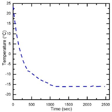
Figure 1 - The temperature profile of the thermo-electric plate during freeze casting of YSZ slurry.
After pouring the ceramic slurry into the mold, the TEC plate was turned on, and the unidirectional freeze-casting of the ceramic slurry was carried out from room temperature (23°C) to -16°C. The freeze-casting temperature profile and the image of the cast ceramic slurry into the mold is provided in Figs. 1 and 2. During the freeze-casting process, the temperature profile was recorded until the process was completed. The freeze-cast samples were then freeze-dried in a Labconco FreeZone2.5 freeze-dryer for 48 hours at -50°C and 300 Pa.
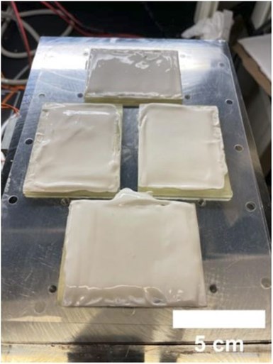
Figure 2 - Freeze casting of YSZ slurry into molds on the surface of the thermoelectric cold plate.
Following freeze-drying, the green bodies were sintered at 1450°C for 4 hours in a ST-1700 C-445 (Sentro Tech) high temperature box furnace in air environment.
The sintering of the green body includes two steps: (i) binder burnout to remove the alginate at 600°C, and (ii) sintering at 1450°C to transform the binder-free green body into sintered ceramics. The heating profile for the two-stage sintering is as follows: increasing up to 600°C at a heating rate of 1°C/min and holding at 600°C for 4 hours; ramping up from 600 to 1450°C at a 1°C /min heating rate; after 4 hours of sintering, the temperature was reduced to room temperature at a 5°C /min cooling rate.
2.3 Bulk density
The bulk density of the YSZ sheets was measured using the Archimedes method. Three samples were prepared for density measurement. The density was measured to be 2.82 ± 0.04 g/cm3 and the porosity was calculated to be 45.50 ± 0.48 %.
2.4 Electron microscopy
A Zeiss Auriga SEM was used to observe pore morphology of the sintered porous YSZ.
2.5 Grain and pore size measurement
The grain size of the sintered YSZ was estimated by the standard intercept count method of ASTM E112-13.8,9 Ten vertical and ten horizontal lines were drawn randomly on, e.g., Fig. 2(A), using ImageJ software to measure the intercept lengths. The drawing of 20 lines yielded a total of 162 boundary intersections, which is sufficient for a reliable analysis. Subsequently, the mean linear intercept length, 𝑙̅, was calculated from 𝑙̅ = 𝑃𝐿, where 𝑃𝐿 refers to the number of grain boundary intersection points along the drawn lines per unit length.10 The pores size measurement was carried out using the ImageJ software.
2.6 Characterization of flexural properties
The flexural strength of porous YSZ was measured using a Shimadzu (AGS-X) universal testing machine. A total of 24 beams were prepared from fine polished YSZ sheets, according to the ASTM standard C1161-18),11 for the three-point bending test. The dimensions of each beam were ~30 mm in length, ~2.2 mm in width and ~1.8 mm in height. The images of the polished YSZ sheet and beams are provided in Fig. S3, in the supplementary materials. The three-point bending test was performed on the beams using a displacement rate of 0.05 mm/min and the span length was fixed to be 10 mm during the testing.

Figure 3 - (A) Images of representative sintered YSZ sheets after polishing; (B) YSZ beams prepared from polished YSZ sheets for flexural test.
2.7 Characterization of thermal shock behavior
The thermal shock resistance of porous YSZ beams was evaluated at temperatures of 200, 300, 400 and 500°C. A batch of thirty beams were prepared from the polished YSZ sheets according to the ASTM standard, and six beams were randomly selected for each test condition. For each test condition, six beams were placed in a rectangular alumina crucible and put inside a box furnace. The beams were then heated slowly to the desired exposure temperature within 30 minutes and equilibrated at that temperature for 15 minutes. After equilibration, the door of the box furnace was opened and the alumina crucible containing the beams was immediately removed with a high temperature tong and the beams were promptly dropped in a DI water bath to induce thermal shock. The water bath temperature was equal to room temperature and the volume was sufficient to prevent the temperature rising more than 5°C after test specimen quenching. The beams were then dried out in a vacuum oven at 110°C for 2 hours. The flexural properties of five beams were measured by three point bending test, following the similar protocol mentioned in Section 2.6. For each test condition, one beam that went through thermal shock was kept intact for SEM imaging. The untested beams were further analyzed using SEM.
3. Results and discussion
Figure 4 shows a schematic diagram of the manufacturing process of porous YSZ. Briefly, the YSZ sheets were fabricated using freeze-casting on a thermoelectric cold plate from an aqueous slurry. The process involves slurry preparation by ball milling, freeze-casting, freeze-drying and sintering. Details of the process are provided in the materials and method section above.

Figure 4 - Schematic diagram of the manufacturing of porous YSZ using the freeze-casting process.
To attain acceptable mechanical properties, it is recommended to sinter the highly porous freeze-casted YSZ at 1450°C or higher temperature.12 Therefore, we selected the minimum recommended temperature of 1450°C as the sintering temperature and selected 4 hours of sintering time to ensure the conversion of the porous green body into a sintered body. Figure 5(A) represents the microstructure of the sintered surface of the porous YSZ. The average grain size was estimated to be ~1.30 ± 0.13 μm using the line intercept method according to ASTM standard E112-13. Most of the grains are hexagonal. A similar grain morphology has been reported in literature for 8 mol% YSZ sintered at 1400°C.13
Figures 5(B) and 5(C) represent the magnified image of open pores at transversely and longitudinally fractured planes, respectively. Based on SEM image micrographs, we observe a combination of spherical and tubular pore morphology, Fig. 5(D). The pore size varies from ~ 20 to 40 μm. In this work, we used a cold thermoelectric plate at a temperature of -16°C and thin sheets (0.18 mm) compared to traditional freeze-casting, in which several-centimeter molds are used for freeze-casting at a much lower temperature using liquid nitrogen.14 It is known that the pore morphology in freeze-casting depends on the freezing temperature and temperature gradient, slurry viscosity, binder and solvent chemistry, particle size and volume fraction, among other factors. Depending on various parameters, various morphologies, including lamellar, spherical, dendritic, among others can be obtained.4,12,15 One of the advantages of using a thermoelectric cold plate for freeze-casting is that the process is potentially scalable (using larger thermoelectric plates). Essentially, the process provides a means of manufacturing porous ceramics with open pores without using pore formers. Oftentimes, a large volume fraction of pore formers is required to create open pore networks.16

Figure 5 - (A) The microstructure of the porous YSZ sintered at 1450°C for 4 hours; (B) a magnified image of pores at a transversely fractured plane; (C) a magnified image of pores at a longitudinally fractured plane; (D) an image of spherical pores and tubular pores; (E) and (F) lower magnification images of the pore morphology at a fractured surface.
The anticipated applications of porous YSZ are for electrodes in SOFCs and SOECs, among others. In both of these devices, the mechanical properties of the electrodes play a significant role in reliable operation, as the electrodes often function as the support structure and must withstand high thermal stresses during the operational cycles and endure various internal and external mechanical loads. The porosity is required to enable gas transport within the electrodes. However, the porosity can also significantly affect the mechanical properties of ceramics.5 To quantify the mechanical properties of the porous YSZ, we conducted flexural tests at room temperature and after thermal shock testing.

Figure 6 - (A) Distribution of the flexural strength of porous YSZ beams; (B) Weibull analysis and characteristic strength of porous YSZ beams (n = 24); (C) an Ashby plot of flexural strength vs density, in which the red dot denotes the porous YSZ in this work.
The flexural testing results of YSZ beams are summarized in Fig. 6(A). The porous beams exhibit a wide distribution of flexural strength from 10 to 26 MPa, with an average flexural strength of 18.15 ± 3.7 MPa. For brittle ceramics, the presence of flaws affects mechanical strength. However, the flaws might not be consistent and not evenly distributed within the samples, and in some samples, flaws may be clustered inconsistently, which might initiate the crack growth during mechanical testing. This should be considered while reporting mechanical strength data and, accordingly, the ASTM standard C1161-13 requires reporting statistical data based on the Weibull distribution parameters.
We report the flexural strength of porous YSZ beams based on two parameter Weibull distribution analysis. The probability of beam failure can be written as 𝑃𝑓 = 1−𝑒𝑥𝑝(−𝜎/𝜎o)𝑚, where 𝑚 is the Weibull modulus, and 𝜎o is the characteristic strength. The Weibull modulus is a shape parameter that translates a specimen’s failure probability over a range of strength levels. The flexural strength of the specimens was ranked in an ascending order and assigned a corresponding probability of failure using 𝑃𝑓 = (𝑖−0.5)/𝑁, where 𝑃𝑓 is the rank of the 𝑖𝑡ℎ specimen and N is the total number of tested specimens. Probabilities of flexural strengths are reported in terms of ln (ln(1/(1−𝑃𝑓)) and ln (𝜎). The characteristic strength of the porous YSZ beams was found to be ~19.62 MPa, shown in Fig. 6(B). The Weibull modulus, 𝑚, is then estimated to be 5.7 by fitting a straight line as the slope of the Weibull plot of ln (ln(1/(1−𝑃𝑓))) against ln (𝜎) with an adjusted R2 value of 0.99.
For engineered ceramics, the Weibull modulus is reported to be in a range from 5 to 10. For 3D printed polymer-derived ceramics m = 3.7 was recently reported.17 For porous materials, it is suggested that the random spatial distribution of pores dictate the range of the Weibull modulus of brittle porous materials.18 Fan, et al.19 reported the value of the Weibull modulus lies within the range from 4 to 11 for porous brittle ceramics.
Generally, m can have any value between 0 and ∞, however, the higher the value of m, the less is the material’s variability in strength. In this work, we have found that the porous YSZ beams exhibited a high variability in the flexural strength, which yielded lower Weibull modulus. From Fig. 5(C), we can see that the pore structure exhibits a uniform distribution. However, it is possible that multiple pores may clump together and form large voids, and thus yield high defect density, which will induce the variability in the results of three-point bending test. Also, during the three-point bending test, the formation and propagation of cracks might vary in different samples, which will induce variability in the flexural strength. Apart from that, the grinding and polishing of YSZ sheets might induce stresses that affect mechanical properties as well. Figure 6(C) represents the characteristic strength of the porous 8YSZ beams, which is superimposed on the Ashby plot. As expected, the mechanical strength of the porous 8YSZ falls in the porous ceramic region.
The electrodes in SOFC and SOEC are subjected thermal stress due to the high temperature ramp rate during the operational cycles. In general, these devices operate at high temperatures ranging from 600 to 1000°C. Additionally, the non-uniform distribution of temperature generated during the operational cycle also leads to significant thermal stress at the cell level.20 In order to quantify the thermal shock behavior of the manufactured YSZ, we followed the ASTM standard (C1525-18).21 Thermal shock resistance was analyzed in terms of the reduction of flexural strength at different temperatures with respect to the room temperature condition. The schematic of the thermal shock testing is shown in Fig. 7(A). Briefly, each beam was subjected to a high temperature for a duration of time, and subsequently was quenched inside a room temperature water container, followed by testing its flexural strength (Fig. 8). To systematically investigate the effect of high temperature on the mechanical strength of the porous YSZ, the initial testing temperature of 400°C was selected. The beams were held at the desired temperature for 15 minutes to obtain thermal equilibrium.
Our results showed that the porous YSZ beams exhibited a lower flexural strength of 10.87 ± 1.73 MPa, which was around ~30.6% - 49.7% lower than the average flexural strength of the beams tested at 25°C. The reduction of flexural strength with respect to the average flexural strength at 25°C was calculated using the upper bound and lower bound values of the flexural strength obtained for the individual test condition.

Figure 7 - (A) The schematic diagram of the thermal shock experiment and the subsequent mechanical testing of porous YSZ; (B) flexural strength of YSZ beams after thermal shock over a temperature range of 200 to 500°C.
According to the ASTM standard (C1525-18),21 the critical temperature difference for thermal shock resistance is determined at such temperature difference between the exposure temperature and the water quenching temperature that induces a 30% reduction in flexural strength compared to the average flexural strength of the specimens tested at room temperature conditions. Further thermal shock resistance of the porous YSZ beams were measured at 200, 300 and 500°C to map the reduction of the flexural strength of the YSZ beams, as summarized in Fig. 7(B).

Figure 8 - Thermal shock test: (A) Taking the beams from the furnace after thermal equilibrium at a desired temperature; (B) quenching the heated beams in DI water and (C) quenched beams in DI water.

Table 1 - Results of the thermal shock experiment for porous YSZ beams.
The reduced flexural strength values of the porous YSZ beams, tested at higher temperature, with respect to the flexural strength are summarized in Table 1. The flexural strength reduction of the porous YSZ beams were below 30% up to a temperature of 300°C. The maximum temperature for the thermal shock resistance measurement was 500°C at which the flexural strength was reduced by 63.5%. From these results, we can determine the critical temperature for the thermal shock resistivity of porous YSZ beams to be 400°C. We did not visually observe any visible cracks on the beam surface after quenching for any of the temperatures tested.
To observe the effects of thermal shock on the porous YSZ, we acquired SEM images of the surface of the beams that were only thermally shocked. We observed no noticeable cracks on the surface of the beams that were thermally shocked at 200°C. However, we observed a significant number of cracks on the surfaces of the beams that were thermally shocked at temperatures of 300 to 500°C. Representative SEM images are shown in Fig. 9.
From Fig. 9, we can observe that cracks have been developed and propagated along the pore distribution channels for all the samples. Also, from the SEM image of the beam thermally shocked at 500°C, we found that the pore structures were exploded and could not retain their original shape. More SEM images are provided in the supplementary Fig. 10. Thus, the development of cracks has yielded poor thermal shock resistivity of the porous YSZ beams.
In general, the strength of ceramics is associated to microstructure, pore size, shape and distribution, and contact (neck area) between particles.22 For example, the flexural strength of spark plasma sintered YSZ evolved from 342.8 MPa to 43.1 MPa for a porosity in the range 8 to 40.1%.23 Nakamura, Keisuke, et al.24 reported that for the increment in grain size of fully dense (6.06 gm/cm3) sintered 3% YSZ specimens from 0.30 to 0.63 μm, the flexural strength decreased from 1167 ± 144 to 1068 ± 176 MPa, which is an 8.48% reduction in the flexural strength. This indicates that the sintered YSZ with larger grains exhibits a tendency to be lower in flexural strength. Therefore, it is obvious that, the high porosity and larger grain size in the fabricated YSZ beams yielded lower flexural strength. Hu, et al. investigated the effect of freezing temperature during freeze-casting of porous YSZ ceramic, for samples as thick as 30 mm, and found that the pore channel size decreased significantly with decreasing freezing temperature (-30 to -196°C). Similarly, the porosity also decreased as the freezing temperature decreased. In addition, they found that samples had remarkably low thermal conductivities (between 0.06 and 0.36 W/m K), which makes them suitable for thermal insulation applications.25 Birchall, et al.26 proposed that larger pores degrade the tensile and flexural strength of brittle materials, such as hydraulic cements. Janssen, et al.27 also reported that pores act as nucleation sites for microcracks for brittle materials.

Figure 9 - SEM micrographs of the surface of thermally shocked YSZ beams tested at temperatures (A) and (B) 300°C; (C) and (D) 400°C and (E) and (F) 500°C.
Figure 10 - SEM micrographs of the surface of thermally shocked beams tested at temperatures (A) and (B) 200°C, (C) and (D) 300°C, (E) and (F) 400°C and (G) thru (J) 500°C.
4. Conclusions
Overall, we show that freezing a thin sheet of YSZ slurry on a cold thermoelectric plate results in a porous ceramic with an open pore network (pore sizes of 20-40 μm), which is ideal for SOFC and SOEC applications. For long term stable operation in these devices, the critical temperature for the thermal shock resistivity of porous YSZ needs to be improved from the current 400°C to well above 800°C. Future studies may focus on engineering the grain size, powder particle size and optimization of the sintering temperature profile, as well as pore morphology, to achieve higher performance porous YSZ.

Figure 10 - SEM micrograph of the surface of thermally shocked beams tested at temperatures (A) and (B) 200°C, (C) and (D) 300°C, (E) and (F) 400°C and (G) thru (J) 500°C.
5. References
1. Y. Chen, N. Wang, O. Ola, Y. Xia and Y. Zhu, “Porous ceramics: Light in weight but heavy in energy and environment technologies,” Materials Science and Engineering: R: Reports, 143 (January 2021), Article 100589.
2. E.C. Hammel, O-R. Ighodaro and O.I. Okoli, “Processing and properties of advanced porous ceramics: An application based review,” Ceramics International, 40 (10), 15351-15370 (2014).
3. F. Zhang, Z. Li, M. Xu, S. Wang, N. Li and J. Yang, “A review of 3D printed porous ceramics,” Journal of the European Ceramic Society, 42 (8), 3351 (2022).
4. S. Deville, “Freeze‐casting of porous ceramics: a review of current achievements and issues,” Advanced Engineering Materials, 10 (3), 155-169 (2008).
5. C.L. Cramer, E. Ionescu, M. Graczyk-Zajac, A.T. Nelson, Y. Katoh, J.J. Haslam, L. Wondraczek, T.G. Aguirre, S. LeBlanc and H. Wang, “Additive manufacturing of ceramic materials for energy applications: Road map and opportunities,” Journal of the European Ceramic Society, 42 (7), 3049-3088 (2022).
6. Y. Man, G. Ding, L. Xudong, K. Xue, D. Qu and Z. Xie, “A review on porous ceramics with hierarchical pore structure by 3D printing-based combined route,” Journal of Asian Ceramic Societies, 9 (4), 1377-1389 (2021).
7. I. Polishko, Y. Brodnikovskyi, D. Brodnikovskyi, B. Vasyliv, V. Podhurska, S. Shevchenko, V. Chedryk, M. Andrzejczuk and O. Vasylyev, “Effect of Porosity on Strength and Electrical Conductivity of NiO–3.5 YSZ Composite and Its Ni–3.5 YSZ Cermet,” Powder Metallurgy and Metal Ceramics, 56 (5-6), 293-304 (2017).
8. ASTM Standard Test Methods for Determining Average Grain Size, in E0112-13R21; ASTM International, West Conshohocken, PA, 2021.
9. G. Vander Voort and A. Gokhale, “Comments on “grain size measurements using the point-sampled intercept technique”, Scripta metallurgica et materialia, 26 (10), 1655-1660 (1992).
10. Z-q.J. Lu, Book review: Adrian Baddeley and Eva B.V. Jensen, Stereology for statisticians, Chapman & Hall/CRC, ISBN 1 58488 405 3, in Statistical Methods in Medical Research, 16 (4), 377-378 (2007).
11. ASTM Standard Test Method for Flexural Strength of Advanced Ceramics at Ambient Temperature, in C1161-18; ASTM International, West Conshohocken, PA, 2019.
12. Y. Du, N. Hedayat, D. Panthi, H. Ilkhani, B.J. Emley and T. Woodson, “Freeze-casting for the fabrication of solid oxide fuel cells: A review,” Materialia, 1, 198-210 (2018).
13. J. Zhang, X. Huang, H. Zhang, Q. Xue, H. Xu, L. Wang and Z. Feng, “The effect of powder grain size on the microstructure and electrical properties of 8 mol% Y2O3-stabilized ZrO2,” RSC Advances, 7 39153-39159 (2017).
14. J. Huang, S. Daryadel and M. Minary-Jolandan, “Low-cost manufacturing of metal–ceramic composites through electrodeposition of metal into ceramic scaffold,” ACS applied materials & interfaces, 11 (4), 4364-4372 (2019).
15. K.L. Scotti and D.C. Dunand, “Freeze casting–A review of processing, microstructure and properties via the open data repository, FreezeCasting.net,” Progress in Materials Science, 94 (C), 243-305 (May 2018).
16. A.B. Haugen, J. Gurauskis, A. Kaiser and M. Søgaard, “Graphite and PMMA as pore formers for thermoplastic extrusion of porous 3Y-TZP oxygen transport membrane supports,” Journal of the European Ceramic Society, 37 (3), 1039-1047 (2017).
17. M. Mahmoudi, C. Wang, S. Moreno, S.R. Burlison, D. Alatalo, F. Hassanipour, S.E. Smith, M. Naraghi and M. Minary-Jolandan, “Three-dimensional printing of ceramics through “carving” a gel and “filling in” the precursor polymer,” ACS applied materials & interfaces, 12 (28), 31984-31991 (2020).
18. Ö. Keleş, R.E. García and K.J. Bowman, “Stochastic failure of isotropic, brittle materials with uniform porosity,” Acta Materialia, 61 (8), 2853-2862 (2013).
19. X. Fan, E. Case, F. Ren, Y. Shu and M. Baumann, “Part I: Porosity dependence of the Weibull modulus for hydroxyapatite and other brittle materials,” Journal of the Mechanical behavior of Biomedical Materials, 8, 21-36 (April 2012).
20. Y. Wang, Y. Shi, X. Yu and N. Cai, “Thermal shock resistance and failure probability analysis on solid oxide electrolyte direct flame fuel cells,” Journal of Power Sources, 255, 377-386 (1 June 2014).
21. ASTM Standard Test Method for Determination of Thermal Shock Resistance for Advanced Ceramics by Water Quenching, in C1525-18; ASTM International, West Conshohocken, PA, 2018.
22. Y. Hirata, T. Shimonosono, T. Sameshima and S. Sameshima, “Compressive mechanical properties of porous alumina powder compacts,” Ceramics International, 40 (1) Part B, 2315-2322 (2014).
23. A. Fregeac, F. Ansart, S. Selezneff and C. Estournès, “Relationship between mechanical properties and microstructure of yttria stabilized zirconia ceramics densified by spark plasma sintering,” Ceramics International, 45 (17) Part B, 23740-23749 (2019).
24. K. Nakamura, E. Adolfsson, P. Milleding, T. Kanno and U. Örtengren, “Influence of grain size and veneer firing process on the flexural strength of zirconia ceramics,” European Journal of Oral Sciences, 120 (3), 249-254 (2012).
25. L. Hu, C.-A. Wang, Y. Huang, C. Sun, S. Lu and Z. Hu, “Control of pore channel size during freeze casting of porous YSZ ceramics with unidirectionally aligned channels using different freezing temperatures,” Journal of the European Ceramic Society, 30 (16), 3389-3396 (2010).
26. J. Birchall, A. Howard and K. Kendall, “Flexural strength and porosity of cements,” Nature, 289 (5796), 388-390 (1981).
27. D. Janssen, R. Aquarius, J. Stolk and N. Verdonschot, “The contradictory effects of pores on fatigue cracking of bone cement, Journal of Biomedical Materials Research Part B: Applied Biomaterials, 74 (2), 747-753 (2005).
6. Past project reports
1. Quarter 1 (January-March 2022): Summary: NASF Report in Products Finishing; NASF Surface Technology White Papers, 86 (10), 17 (July 2022); Full paper: http://short.pfonline.com/NASF22Jul1 .
7. Acknowledgements
This research is supported by the US National Science Foundation (CMMI award number 2152732) and AESF foundation under the AESF Foundation Research Program.
8. Author Contributions
Dr. Minary Jolandan and Mr. Faisal Riyad designed the research. Mr. Faisal Riyad carried most of the experimental work. Mr. Mahmoudi did the SEM imaging and assisted in the thermal shock experiment. Dr. Minary Jolandan and Mr. Faisal Riyad contributed to the writing and editing of the manuscript.
9. Data availability
Data are available upon request from the corresponding author.
10. About the Principal Investigator for AESF Research Project #R-123

Majid Minary Jolandan is Associate Professor, Mechanical and Aerospace Engineering, School for Engineering of Matter, Transport and Energy, in the Ira A. Fulton School of Engineering, at Arizona State University, Tempe, Arizona. His group is interested in various manufacturing processes to address current national challenges in advanced materials. Current interests in his group include advanced and additive manufacturing and multifunctional and smart materials.
His education includes B.S. Sharif University of Technology (2003), M.S. University of Virginia (2005), Ph.D. University of Illinois at Urbana-Champaign (2010) as well as Postdoctoral fellow, Northwestern University (2010-2012). From 2012-2021, he held various academic positions at The University of Texas at Dallas and joined the Faculty at Arizona State in August 2021.
He teaches advanced manufacturing, mechanical behavior of materials and structural mechanics in the School for Engineering of Matter, Transport and Energy.
Early in his career, he received the Young Investigator Research Program grant from the Air Force Office of Scientific Research to design high-performance materials inspired by bone that can reinforce itself under high stress. This critical research can be used for aircraft and other defense applications, but also elucidate the understanding of bone diseases like osteoporosis.
He also earned the Junior Faculty Research Award as an assistant professor at the University of Texas-Dallas School of Engineering.
* Corresponding author:
Dr. Majid Minary Jolandan
Associate Professor of Mechanical and Aerospace Engineering
School for Engineering of Matter, Transport and Energy
Ira A. Fulton School of Engineering
Arizona State University
Tempe, Arizona
Phone: (217) 714-6776
Email: majid.minary@asu.edu
RELATED CONTENT
-
Qualitative Approach to Pulse Plating
In 1986, the AESF published Theory and Practice of Pulse Plating, edited by Jean Claude Puippe and Frank Leaman, the world’s first textbook on pulse plating. A compendium of chapters written by experts in this then-emerging field, the book quickly became the authoritative text in pulse plating. What follows here is the opening chapter, serving as an introduction to the field. Although the field has grown immensely in the intervening 35 years, the reader will find that the material remains a valuable introduction to those looking to advance the field of pulse plating.
-
Electroplated Tin-Nickel Coatings as a Replacement for Nickel to Eliminate Nickel Dermatitis
This paper is a peer-reviewed and edited version of a paper delivered at NASF SUR/FIN 2013 in Rosemont, Ill., on June 12, 2013.
-
Plastics and Plating on Plastics [1944]
This republished 1944 AES convention paper presents an historic perspective of the early days of plastics in surface finishing - using them and plating on them, in the waning years of World War II. The discussion reviews the uses of plastics in plating equipment and processing at that time, as well as the coating of the plastics themselves, with accompanying application photos. You will note that today’s conventional plating-on-plastics processes lay far in the future. Surprisingly, CVD processes are discussed.


