Corrosion Testing of Automotive Coatings
Exposure to road salts, UV radiation, heat, moisture and chipping from kicked-up road debris can quickly degrade an automotive coating system.
#masking #automotive #pollutioncontrol
Exposure to road salts, UV radiation, heat, moisture and chipping from kicked-up road debris can quickly degrade an automotive coating system. To continually improve coating performance, companies seek to mimic and accelerate real-life exposure conditions in the laboratory.
Recent years have seen a marked improvement in automotive coatings technology, and laboratory testing has played a key role.
Featured Content
A common test involves the purposeful damage of the coating layer to determine a property referred to as rust creep, a quantitative measure of how far the corrosion travels along the substrate/coating interface to either side of a mechanically-induced scratch during exposure to a corrosive environment—typically a neutral salt spray or cycle corrosion test. Rust creep results are used to determine whether a coating process meets the automotive manufacturer’s stringent requirements.
The scribing process can be performed on standardized flat test panels, or on the actual automotive component, if size and geometry permit. Some test specifications call for a single linear scribe, whereas others specify an intersecting set of two scribes, such as seen in Figure 1.
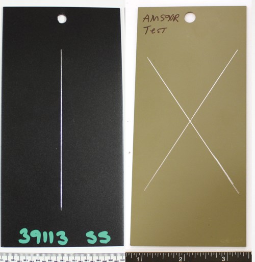
Figure 1: Examples of a single linear scribe (left) and an X-scribe (right).
A variety of scribing tools are used for this type of testing, depending on the automotive manufacturer. One might specify use of a relatively thin steel razor blade, whereas another will specify a rounded carbide tip. Variables such as the type of scribe used, sharpness of the scribing tool and pressure applied by the scribe operator can affect the final rust creep.
But can scribing tool selection significantly affect rust creep results? To answer this common question within the coatings testing community, we evaluated the effect of scribing tool geometry on the resulting groove profile as well as its effect on the degree of rust creep that develops during corrosive exposure.
Test Panel Prep
Testing was performed on off-the-shelf 3- by 5-inch cold rolled steel test panels. Fifty panels underwent a zinc phosphate pretreatment followed by electrocoating using a high edge build (HE) cathodic epoxy formulation. Of these, half were set aside and labeled as group “E.” The remaining panels had a powder coating applied on top of the electrocoated surface and were labeled as group “P.” Using ferromagnetic techniques, average coating thickness was determined to be 25 and 100 microns, respectively.
Four scribing tools commonly used by the automotive industry were used to scribe the test panels. The tools are described in Table 1 and shown in Figure 2.
Table 1. Description of Scribing Tools Used in This Study
|
Scribing Tool |
Description |
|
Sikkens Model 463 |
Square blade |
|
Van Laar Model 426 |
Rounded Tip |
|
Clemen Model 428 |
Rounded Notched Tip |
|
Box Cutter |
Razor Blade |
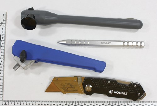
Figure 2: A sample of scribing tools commonly used for rust creep determination. Top to bottom: Sikkens Model 463, Van Laar Model 426, Clemen Model 428, razor blade.
Two technicians, Operator ”A” and Operator “B,” each scribed two panels using all of the four scribing tools with a target scribe length of approximately 10 cm. A single scribe was made and penetrated the entire thickness of the coating such that the underlying steel could be seen. This resulted in 16 scribed Group E panels and 16 scribed Group P panels, as described in Table 2, for a total of 32 test panels. One panel from each scribe/technician/coating combination was sectioned through the scribe prior to corrosion testing as outlined in Figure 3. The other panel of each pair was left whole.
Table 2. Description of Prepared Panels, Electrocoat Only and Electrocoat + Powder
|
Tech A |
Tech B |
|
|
Square: Sikkens (463) |
2 |
2 |
|
Rounded: Van Laar (426) |
2 |
2 |
|
Notch: (428) |
2 |
2 |
|
Razor Blade |
2 |
2 |
|
Total Panels Each Coating System: |
16 |
|
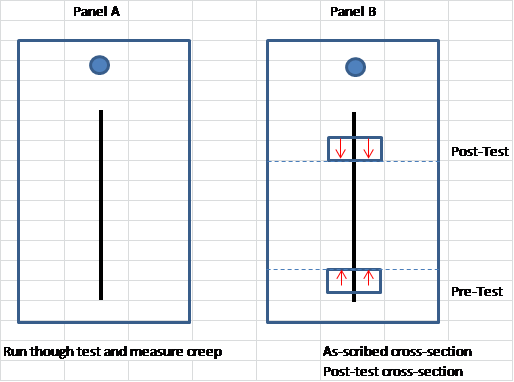
Figure 3. Schematic showing test panel scribe and metallography sample locations.
The removed metallography sections were vacuum embedded in clear epoxy, which was chosen as the best mounting technique to preserve the original profile of the scribe and displaced coating. The cured specimens were ground and polished using standard metallographic techniques, then examined in the as-polished condition with an optical microscope. Figures 4a-d show the resulting scribes in cross-section, where the coating layer has been digitally highlighted to delineate it from the clear epoxy mounting material. The images are for the Group E samples, but are also representative of the Group P samples—with the exception that the coating layer was thicker on the Group P samples. The razor blade resulted in the deepest damage to the underlying steel panel surface.
Figure 4. Resulting cross-section geometries from Sikkens/square (a), Van Laar/round (b), Clemen/notch (c) and razor blade (d). The damaged coating layer has been digitally enhanced in red for emphasis.
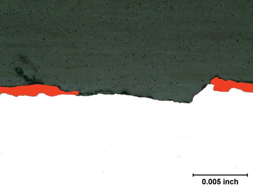
Image a.
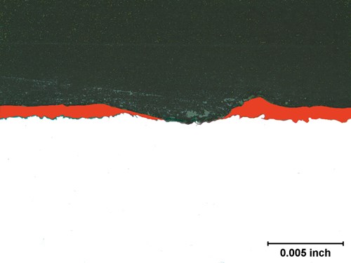
Image b.
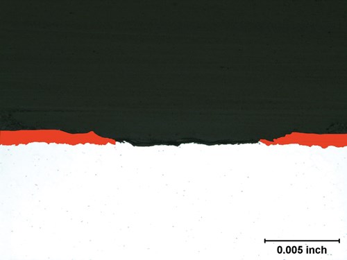
Image c.
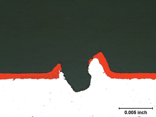
Image d.
Exposure and Measurement
The 16 sectioned panels were taped along the cut edge to minimize rust run-off, then all 32 panels were placed in a programmable cyclic corrosion chamber using a slotted panel rack. The panels were exposed to six cycles of ISO 11997-1 (2005), Cycle B, a standard cycle corrosion test consisting of a combination of neutral salt spray exposure according to ASTM B117/ISO 9227, 100 percent condensing humidity according to ISO 6270-2 CH, drying and dwelling. One full corrosion cycle is a week in duration. Figure 5 shows a typical panel after the six-week exposure. Rusting was observed at the panel hanging hole as well as along the scribe. No other surface rusting or edge rusting was observed on any of the panels.
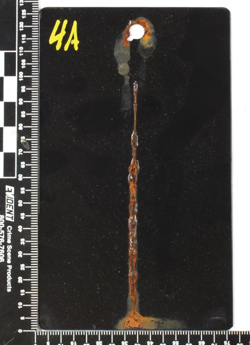
Figure 5. A typical panel is shown following the six-week cycle corrosion test. Some rust run-off was observed from the scribe and stamped panel hole.
The post-exposure cross-section sample was cut from each of the 16 panels that previously had a pre-exposure sample removed. These sections were metallographically prepared in the same manner as the pre-exposure samples and retained for future reference. The remaining scribes were gently scraped with a knife blade to remove any flaked or blistered paint along the edges of the scribe. Rust creep measurement was performed by a trained third individual (neither Operator A nor B) by taking five measurements along the length of the scraped scribe. The creep was measured edge-to-edge of the rusted region using digital calipers, then averaged for each panel. Figures 6 a and b show resulting rust creep measurements for Operators A and B for both types of panels (electrocoat only and electrocoat plus powder).
Figure 6. Average raw edge-to-edge rust creep measurements for Operators A and B for E and P panels.
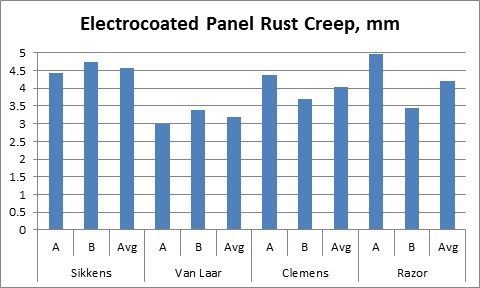
a.
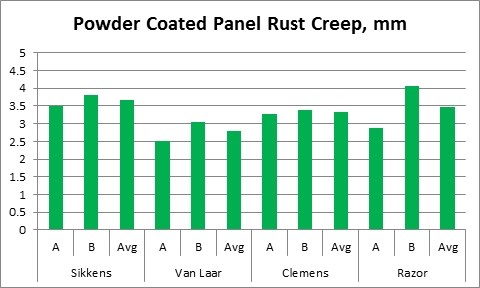
b.
Conclusions
The variation of the rust creep was surprisingly low as a function of scribe type and operator. The standard formula for calculating rust creep is as follows: Creep = (wc-w)/2, where wc is the average raw creep measurement and w is the original width of the scribe. Once this formula was applied to the raw data shown in Figure 6, the variation in calculated rust creep was only 0.6 mm across all four scribing tools and operators for the electrocoated panels and only 0.4 mm for the powder coated panels.
Other conclusions resulting from this study include:
- The Sikkens scribe provided the most uniform rust creep readings among operators.
- The rust creep measured along the scribe made by the relatively narrow razor blade resulted in the greatest standard deviation between individual rust creep measurements for both the Group E and Group P panels. This was likely attributed to the relatively deep penetration into the substrate and significant deformation and non-uniform displacement of the coating.
- The rounded carbide tip of the Van Laar 426 scribe resulted in the lowest average observed rust creep. This characteristic is likely the result of less aggressive damage imposed on the surface of the test panel and minimal tearing of the coating.
- Addition of the powder coating layer lowered the overall degree of rust creep for all scribe types used in the study.
- There was a correlation when comparing Operator A to Operator B to rust creep measurement, in that Operator A’s scribes resulted in lower creep measurements in six of the eight test conditions. This indicates that scribing characteristics, such as applied pressure and general technique, may influence final rust creep measurements.
Tom Ackerson, PE is the laboratory Director at IMR Test Labs, Louisville; he can be reached at tom.ackerson@imrlouisville.com. Jennifer Breetz is also with IMR Test Labs and can be reached at jennfer.breetz@imrlouisville.com. The authors wish to acknowledge the assistance of the following: Chuck Gault, Max Coatings, Birmingham, Alabama, for providing the coating services; Max Calenberg and Justin Barnes of IMR Test Labs, Louisville, Kentucky, for assistance in sample preparation.
RELATED CONTENT
-
Plating Process Control
The cornerstone of quality and productivity for any finishing operation, process control is a plater’s key to success. To find out how far techniques have come, where they’re headed in the future, and how platers can raise the bar, Products Finishing convened a panel of experts for a roundtable discussion on the topic. With well over 100 years of combined plating experience, experts Greg Arneson, Art Kushner, Peter Gallerani and Joelie Zak share their thoughts.
-
Troubleshooting for Electrocoating
Characterizing the type of defect is essential in identifying the root cause and eliminating its source...
-
Fundamentals of Liquid Coatings for Finishing Operations
Before liquid coatings are selected for the industrial finishing line, it is important to have a solid understanding of how a coating works.


