The Benefits of Automated Selective Plating
More companies are relying on the consistency and traceability that automated processes provide, so why would selective electroplating be any different? Selective plating is a method of electroplating localized areas without the use of an immersion tank. Automated equipment has recently been developed for some very challenging applications. Fully customized machines can be designed for repair or OEM applications to apply engineered deposits without the need for operator intervention, changing the perceived notion of a once highly manual operation. This presentation highlights the key benefits of automating the selective plating process.
#surfin
Featured Content
A Paper* based on a Presentation given at SUR/FIN 2019 (Rosemont, Illinois)
by
Derek Kilgore**
SIFCO Applied Surface Concepts
Independence, Ohio, USA
Editor’s Note: The following is a paper based on a presentation given at NASF SUR/FIN 2019, in Rosemont, Illinois on June 5, 2019 in Session 14, Advancing Technology Applications for Finishing / Engineering Opportunities. A pdf of this brief can be accessed and printed HERE; the complete Powerpoint presentation is available by clicking HERE.
ABSTRACT
More and more companies are relying on the consistency and traceability that automated processes provide, so why would selective electroplating be any different? Selective plating is a method of electroplating localized areas without the use of an immersion tank. Automated selective plating equipment has recently been developed for some very challenging applications. Fully customized machines can be designed for repair or OEM applications to apply engineered deposits without the need for operator intervention, changing the perceived notion of a once highly manual operation. This presentation highlights the key benefits of automating the selective plating process including safety, ergonomics, eliminating operator error, process consistency, data capturing and reporting, part traceability, optimized solution management, minimized emissions, and space savings.
Introduction and background
Selective plating was originally developed in 1938 in Paris, France by George Icxi. It evolved from the simple touch-up of tank plated parts. In 1959, the Steel Improvement and Forge Company (also known as SIFCO Industries) bought a Canadian-based firm and moved all operations to Cleveland, Ohio. In 2012, SIFCO ASC was acquired by Norman Hay, headquartered in the UK. NH was originally founded in 1940 doing chromium plating and hard anodizing. Norman Hay was acquired by Quaker Houghton in October 2019.
Selective plating concepts
Selective plating, or more commonly brush plating, is a portable process for plating localized areas on a workpiece without the use of an immersion tank. There are four key elements to a brush plating set-up, shown in Fig. 1:
- The workpiece, in this case is the inner diameter of a cylinder that is being rotated by a turning head fixture on the right.
- The power pack, with current, voltage and amp-hr control, on the left.
- The plating tools, the anode here inserted into the hole in the workpiece, and
- The preparatory and plating solutions, contained in the tank in the solution flow system, center.
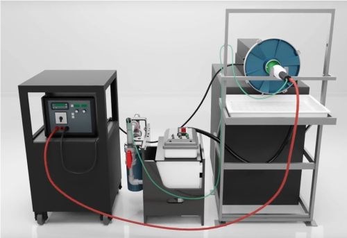
Figure 1 - Typical setup for selective / brush plating.
The anodes can consist of graphite, Dura-A-Form®, platinum, or platinum-clad niobium or titanium. They are typically made to conform to the substrate to optimize thickness distribution. The red and black cables connect the power source to the anode and workpiece, and the green and black tubing provide solution circulation between reservoir and workpiece.
The rest of operation decisions are based on if the plating solutions need to be heated, flowed, or dipped, how the workpiece is to be masked to isolate the selected area, and whether any auxiliary equipment is needed to hold or rotate the part and/or or the plating tools.
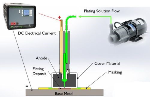
Figure 2 - Selective plating operation.
As shown in Fig. 2, an electrolyte containing metal ions is introduced between a positively-charged anode (i.e., the preparatory or plating tool) and a negatively-charged cathode, (i.e., the workpiece). The anode itself is wrapped with a material that can be made of cotton, PermaWrap®, red or white TuffWrap®, etc. The wrap serves two main functions: to prevent an anode to cathode short-circuit and to act as the carrier for the solution which helps facilitate the current flow by wetting both electrodes to create the electrochemical cell. The solution can be introduced to the workpiece by flowing the solution through the anode using an external pump or by dip plating, where the anode is dipped into a beaker sitting near the workpiece.
A typical plating scheme consists of several preparatory steps that prepare the surface for the final metal deposition step. Each prep step requires a dedicated anode. The prep steps usually entail electroclean, etch, desmut and activation of the surface of the workpiece. The part is rinsed in between steps with DI water to avoid cross contamination and assure a clean work surface. After the workpiece has been properly prepared, a nickel preplate is typically applied and is substrate dependent.
Selective plating versus standard tank plating
Selective plating offers a number of advantages that regular tank immersion plating cannot offer. The process is portable. Deposition rates are considerably higher, owing to higher metal concentrations in solution. The high solution velocity involved offers ready replenishment of metal ions at the surface. The inherent brushing action disturbs the hydrodynamic boundary layer at the surface resulting in faster solution movement. As a result, hydrogen gas bubbles are removed by the brushing action and high solution velocity.
Beyond the deposition process itself, the need for part masking is reduced. The process is ideal for large parts not suited for tank immersion baths. Finally, the nature of the operation reduces the solution volumes needed for plating.
Manual selective plating
As with tank plating, selective plating does involve numerous manual tasks, including, among others:
- Parts handling
- Post-plating visual inspection
- Modifying rectifier settings (current and voltage)
- Changing and positioning anodes
- Opening and closing valves
- Rinsing parts
- Moving and disposing of chemical trays
- Monitoring and documenting rectifier settings (current, voltage and electric charge passed (A-hr))
- Adjusting charge passed, based on solution life
- Maintaining solution chemistry
- Detecting equipment issues
Variations can occur during the plating process, from part to part as well as from operator to operator. The process must also be documented for quality assurance, and there is little time to properly monitor and record the actual versus the targeted process settings. In sum, many of the tasks are subject to repetitive routine for the operator and considerable variability in the result.
Automated selective plating
Many of the repetitive tasks and variability can be alleviated by automation. In any manufacturing process, automation can be used to:
- Increase labor productivity (greater output per hour of labor input)
- Reduce labor cost
- Mitigate labor shortage due to unavailability of specialized training
- Reduce or eliminate routine manual tasks
- Improve worker safety
- Improve product quality
- Reduce manufacturing lead time
- Accomplish processes that cannot be done manually
Selective plating offers several possibilities in which automation can result in significant productivity gains and cost reduction, in line with the above list.
Rectifier software control
As noted earlier, manual rectifier control is subject to operator variability. Software is available to regulate the current and voltage applied, as well as record the data for each individual part run. Here, automation frees the operator from adjusting rectifier, and the results are repeatable and reproducible. With the operating current, voltage and charge applied consistently, the deposit properties can be optimized. Increased throughput and fewer errors are realized. As shown in Fig. 3, data logging captures the actual amperage, voltage and time for the entire process cycle, from surface preparation through final plate. Overall, improved quality control and assurance are obtained.
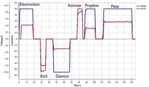
Figure 3 - Typical programmed rectifier data report.
Mechanized solutions
Programmable software need not be just limited to rectifier control. It can also be used to assist the operator with many of the manual tasks associated with the selective plating processes. The software can be used to change and move anodes, open and close valves, rinse parts and move and dump chemical trays. What follows are three examples of applications where automated selective plating operations have been successfully applied.
Application 1: Oil well blow out preventer (BOP)
This application involved corrosion protection for an oil well blowout preventer (Fig. 4). The objective was to prevent corrosion damage inside critical seal pockets. These parts required repair / refurbishment in order to utilize them again in the field. The desired turnaround time was four to six parts every four to six weeks. The substrate material was F22 carbon steel. The electroplated layer specified was 0.030-0.060 in. of nickel. The plating process cycle was (1) electroclean, (2) etch, (3) desmut, (4) sulfate nickel preplate (strike) and (5) sulfamate nickel plate.
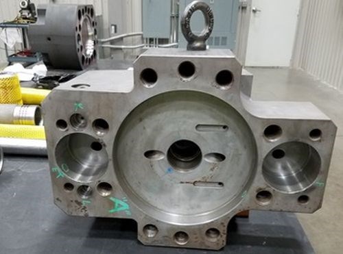
Figure 4 - Oil well blowout preventer part.
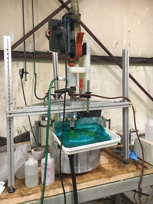
Figure 5 shows the pilot scale manual plating apparatus used in the proof-of-concept phase of this study. The off-center pockets required anode rotation by means of an ID plater. Figure 5(a) shows the rotating anode device, with several anode configurations displayed beside it to accommodate the various recess diameters. Figure 5(b) shows the complete installation with the rotation axis positioned vertically.
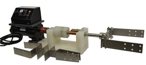
(a)
(b)
Figure 5 - Manual selective plating pilot apparatus: (L) rotating anode assembly; (R) complete pilot scale setup (vertical orientation).
Some problems were noted. Plating with the rotating axis positioned horizontally required flipping the part 180° to prevent uneven thickness distribution. Plating vertically prevented flipping parts by flooding the pocket. It was difficult to align the rotating anode assembly with the bore using the mechanical setup shown in the photo. Any misalignment created rapid wear of the anode wrap material. Further, increased labor was involved with additional setup and masking time.
Given these observations, a semi-automated machine was built to increase throughput and reduce the changeover time (Fig. 6). Automated PLC controlled servos and digital position readouts were provided for precision anode alignment. Part locating tooling, masking fixtures and rectifier software control were included. Automated valves were installed to eliminate this manual task. The operator would still prepare the plating area with hand tools, and carbon filter ventilation was provided.
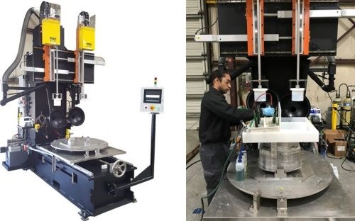
Figure 6 - Semi-automated machine for Ni plating of oil blowout preventer: (L) general view; (R) installation in operation.
Significant benefits accrued from the semi-automated machine. Increased throughput was realized by plating two areas at the same time. Productivity improvement was gained by decreasing setup and masking time, with reduced labor. Process control and consistency was enhanced with anode alignment repeatability, and optimized deposit properties were obtained with standardized plating recipes. Data logging recorded the actual amperage, voltage and ampere-hours for every part.
Table 1 shows the total productivity improvement obtained with this application. While the manual ID plater improved the bore processing time, the vertical orientation provided a marginal improvement. Significant improvement was achieved with the semi-automated installation, reducing human errors and reducing the lead time from 25 days to 8 days to finish one part.
Table 1 - Installation 1: Total productivity improvement

Application 2: Pre-braze nickel layer on an engine vane
The application here was to deposit a pre-braze 0.0001-0.0003-inch thick layer of nickel on Rene 80, a nickel-based alloy used in jet turbine blades. The objective was to prevent corrosion damage inside critical seal pockets. The existing process was labor intensive to the point where there were ergonomic concerns. The part geometry was difficult to mask, and part handling required that the parts be brought to the anodes, rather than the reverse. The larger production volume involved required a dedicated person for the operation.
Here, a robotic plating system (Fig. 7) was developed which featured a programmable logic control (PLC) rectifier with human machine interface (HMI) recipe control. Robotic part handling was employed to bring parts to anodes. The system also contained an automated DI water rinse and air blow off, a part load conveyor and an unload table.
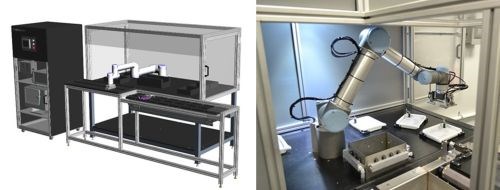
Figure 7 - Robotic selective plating system: (L) overall layout; (R) robotic handling arm and ancillary equipment.
The benefits of automating this application included ergonomic risk reduction, labor savings, optimization and standardization of cycle times, process control and consistency, process capability improvement from 1.50 to 4.15 Sigma, reduced human errors and chemical exposure reduction.
Application 3: Pre-braze nickel layer on turbine engine components
The application here, also related to turbine engines, was to apply a pre-braze 0.0002-0.0006-inch thick layer of nickel on Inconel, an austenitic nickel-chromium-based superalloy. The objective was to replace aging tank plating equipment with automated selective plating equipment. The logistics of this process were complex, involving 10 to 30-inch diameter workpieces. Part masking, involving wax dipping and cutting, was time consuming. A large manufacturing space requirement of 7000 ft2 was typical for such an installation (Fig. 8). In addition, operator chemical exposure, environmental requirements and the use of an air scrubber had to be dealt with.
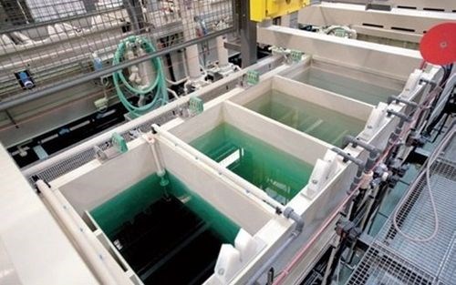
Figure 8 - Portion of a tank line for nickel plating Inconel turbine engine components.
A fully automated robotic selective plating system was developed for this application. It included:
- Quick change masking tooling
- Anode tool changers
- Solution level and flow control/monitoring
- RFID tag monitoring
- Barcode driven recipe selection
- Programmable logic controlled (PLC) rectifier
- Data collection/reporting
- Provision for operators fill solution tanks on a weekly basis
- Rinse water collection tanks
- Carbon filter fume extraction with airflow switch

Figure 9 - Details of quick-change tooling mechanism.
The system allows for quick change tooling for fast changeovers and precision locating. As shown in Fig. 9, air pressure causes the cylinders to unlock and receive and locate their mating retention knobs. Removing air pressure from the cylinder allows the internal piston cam to mechanically position five hardened steel balls around the knob, locking it into place until air pressure is again applied to release it. The precision surfaces of the cylinder locks and mating knobs offer a repeatability of .0002″, with thousands of pounds of fail-safe mechanical holding strength. Accordingly, there is no need to center the part in a traditional lathe chuck, eliminating the need for operators to manually center parts into traditional lathe chucks.

Figure 10 - Details of master anode tool changer.
A master anode tool changer is fitted with plumbing to handle all plating chemicals, DI water, compressed air, electrical connectors and an RFID tag reader. The robot picks and places each tool in plating process in sequence. Poka-yoke (mistake-proofing) plumbing and RFID tags prevent using wrong tool or chemical. A collision sensor was provided to prevent crashing tooling.
Solution handling constantly monitored critical operating parameters. The pump flow is PLC-controlled, and clamp-on flowmeters are installed for data feedback. Sensors monitor the solution tank level and temperature, and the specified nickel plating is regulated through ampere-hour tracking. Automated valving is used to divert recirculated chemicals and rinse waters to their proper locations. Rinse water collection tanks store prep waste and nickel waste before being pumped to larger totes. Separating these waste streams means that the nickel wastewater can later be recycled and reclaimed.
Summary
Overall, automating selective plating operations can offer:
- Optimization and standardization of cycle times
- Increased throughput and productivity
- Process control and consistency
- Reduced human errors
- Reduced labor
- Ergonomic risk reduction
- Chemical exposure reduction
- Data logging and reporting
- Reduced manufacturing space
- Possible elimination of air scrubbers
As seen here, selective plating is not just a manual process. There are many different reasons to automate a selective plating process. However, it is important to understand your application and what goals you have in automating your process.
About the author

Derek Kilgore is a Mechanical Design and Project Engineer at SIFCO ASC.
*Compiled by Dr. James H. Lindsay, Technical Editor - NASF
** Corresponding author:
|
Mr. Derek Kilgore Mechanical Design and Project Engineer SIFCO ASC 5708 E. Schaaf Road Independence, OH 44131 Phone: 216-750-2219 Email: dkilgore@sifcoasc.com |
RELATED CONTENT
-
Electroless Nickel-plated Steel versus Stainless Steel: Case Studies
This paper highlights two case studies of manufacturers that have replaced, or done studies to replace, stainless steel with electroless nickel-plated mild steel. In both cases, cost savings could be realized while maintaining or improving product quality.
-
A Pulse/Pulse Reverse Electrolytic Approach to Electropolishing and Through-Mask Electroetching
Research at the authors’ laboratories has focused on pulse/pulse reverse electrolysis on cathodic processes, such as hard chromium plating from non-hexavalent chemistries. This papers describes studies into pulse/pulse reverse electrolysis as applied to electrochemical metal removal processes, such as electropolishing and electroetching.
-
Hybrid Sol-Gel Coatings in Surface Engineering
A look at the use of modified sol-gel polymer films and hybrid system coatings, as well as the methodologies for evaluating the mechanical properties of the coatings.


