
Share

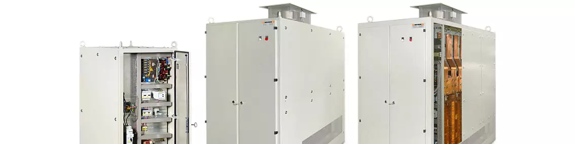
Replacing old SCR rectifiers may help lower electrical costs, but choosing between modern SCR (left) and SMPS rectifiers (right) requires some careful consideration. Source | American Plating Power LLC.
Maybe you’ve heard this one: You can save 40% on your electric bill by replacing a silicon-controlled rectifier (SCR) with a switch-mode (SMPS) rectifier. Or what about: Power factor penalties caused by SCR rectifiers can add significant energy costs? How about: Measuring line current is all you need to be concerned about in order to understand your electrical costs?
None of the above statements are true.
Featured Content


At the end of the day, a plating rectifier comprises a transformer that lowers a utility’s high voltage to the 6–18 volts typically used by electroplaters (or to the somewhat higher voltages required by anodizers), a rectification system that changes alternating current (AC) to direct current (DC), and regulators, controls and a means of cooling the various components.
There are many misconceptions in the metal finishing industry about energy savings when changing from SCR to SMPS rectifiers. Although some savings are possible, the real-world savings are only significant in specific circumstances. The factors that affect energy savings are complicated and contribute to the confusion. The good news is that there are a variety of power supply technologies available today that can ensure you have the best rectifier for your application and production environment.
SCR versus SMPS
There are substantial design differences between SCR rectifiers and SMPS rectifiers. The most significant is the number of steps needed to convert alternating current (AC) to direct current (DC) power. SCRs operate on line power frequency (60 Hz) and have fewer power conversion steps to produce DC. SMPS units are more complicated and produce DC at a much higher operating frequency (10,000 Hz or higher). Because of this difference, SMPS theoretically can operate more efficiently than SCR rectifiers. However, in practice, there are factors that diminish these theoretical cost savings.
If you have SCR rectifiers that are decades old, they are less efficient than today’s SCRs. Modern SCR designs are nearly as efficient as SMPS when run at full power. A modern SCR rectifier should be designed for 100% duty factor and should not be oversized for the application. Oversizing causes you unnecessary equipment expense. SCR inefficiencies only come into play when you run the rectifier at reduced DC voltage output. The lower the DC voltage setting relative to the designed output of the unit, the lower the operating efficiency of the SCR. Lowering the output current has very little effect on the rectifier’s efficiency.
Power factor
Power factor (PF) is explained as the ratio of the real power absorbed by a load to the apparent power flowing in a circuit. To understand PF, we need to review some additional terms: kilovolt-ampere (kVA), kilowatt (kW) and kilovolt-ampere reactive (kVAR). KVA is the apparent power flowing in the circuit. KW is the real power absorbed by the load (and what you pay for). KVAR is the reactive power flowing back and forth between the circuit and the power grid.
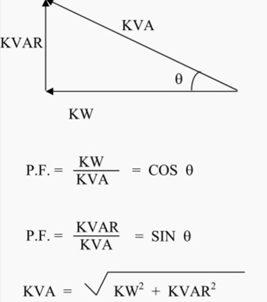
The Power Triangle
The power factor equation is as follows: PF = kW/kVA. This is how much power the rectifier is taking in, not the real power to drive the load (that is, the process). PF should not be confused with the efficiency value.
SMPSs have a better PF than SCRs at output voltages lower than 100% because the SMPS waveform is created after the input diode bridge. A typical, full-wave-rectification, six-pulse, three-phase SCR produces full phase-angle all the time. An SCR unit sine wave looks similar to the SMPS sine wave below, but only at full output voltage.

Here’s a comparison of an SMPS (left) vs. SCR partially on (right).
Because phase-angle control is used with SCR technology, the amount of available line voltage and power to the load is limited. When you turn down the output voltage of an SCR rectifier, the PF might go to 0.6. Conversely, the closer you turn the SCR unit to full output voltage, the closer to full-wave rectification you get.
Electrical costs
The electrical utility cares about PF because they have to size the service to handle the apparent power (kVA) as well as the real power (kW). Most utilities charge based on two factors: total consumption and peak demand (PD). PD is the highest capacity you require during a given billing period (typically a 15-minute interval during a billing cycle or audit period). You can think of it this way:
Consumption is like your car odometer. It tells you how far you have driven. PD is your speedometer at the moment you hit your maximum speed. Utilities charge for the cost (plus profit) of the product, that is, consumption, and the cost for making the product available, that is, overhead.
So, to best lower your PD needs, you have to take a more comprehensive approach to your overall energy usage rather than simply thinking a different type of rectifier is the answer. Although an SMPS rectifier has a higher PF rating than an SCR rectifier, the PF difference only translates to a modest savings in typical applications. A maximum of 3% of your total cost to run the system can be attributed to PF. For example, let’s say you have a 30VDC rectifier operating at 22VDC and the PF penalty is an average of $0.009/kVAR/h. An SCR unit would have a PF of around 0.7, which results in 40% higher input power intake versus an SMPS with a PF of 0.9 or better. The penalty would not exceed 2-3% of the total kWh you are paying for. Having less reactive power (kVAR) means the closer kVA is to kW. When the PF is 1, kVA and kW are the same value.
Measuring the line current only gives you an indication of reactive power (kVAR) and real power (kW) vector sum together. You do not necessarily pay for the reactive power. Actual costs vary depending on your location, but, in general, up to 50% kW consumed during peak times is provided as no-charge kVAR before any penalty kicks in. This explains why the utility requests only 0.9 PF and not 1. This reactive energy helps to stabilize the grid. Not all kVAR is bad. Some is actually beneficial. The kVAR penalty normally only applies when the SCR rectifiers are running below their designated output spec for DC voltage.
Consider PF correction for the entire facility and check each rectifier to be sure they are all running correctly. If you find an SCR rectifier that is running at 25% efficiency, it is likely running at a fraction of its rated output voltage or in serious need of repair.
In conclusion, if you have old SCR rectifiers, you should seriously consider replacing them with new rectifiers. You can reduce energy consumption whether you choose SCR or switch mode. There is not a large difference in energy savings solely based on power factor between the two types of rectifiers. However, if you typically run your SCR rectifiers at reduced DC output, you can save on energy consumption if you switch to properly-sized SCR rectifiers. Switch-mode rectifiers do not have this issue as they maintain high efficiency through essentially their entire power range. Reducing peak demand for your facility is just as important as lowering overall energy consumption to achieve maximum energy cost savings. Consider an audit of the entire facility to maximize your energy-expense savings.
About the Author
Doug Delaney is a senior applications engineer with American Plating Power LLC and has more than 23 years of power supply experience ranging from equipment design to new product innovation and customer technical support.
RELATED CONTENT
-
Cleaning, Pretreatment to Meet Medical Specs ISO 13485 or FDA 21 CFR820
Maximilian Kessler from SurTec explains new practices for industrial parts cleaning, metal pretreatment and decorative electroplating in the medical device industry.
-
Blackening of Ferrous Metals
The reasons for installing an in-house cold blackening system are many and varied.
-
An Overview of Electroless Nickel Plating
By definition, electroless plating is metal deposition by a controlled chemical reaction.


