
Troubleshooting Chromium Conversion Coatings on Aluminum
This paper provides processors with an extensive troubleshooting tool when conversion coating failures are encountered.
#research #surfin
Share
Editor’s Note: The following is a technical paper accompanying a presentation given at NASF SUR/FIN 2019, in Rosemont, Illinois on June 4, 2019 in Session 11, High Reliability Aerospace and Defense Processes.
The reader is urged to access both documents to gain a full understanding of the significance of this work.
ABSTRACT: Chemical processing steps for chromium conversion coatings are well defined and have been used in the metal finishing industry since first developed in 1946.1 They are widely used for aluminum surface treatment when electrical conductivity is required or the fatigue impact of anodize is too great. The purpose of conversion coatings is predominantly to promote adhesion of the subsequently applied organic film. In addition, conversion coatings change the chemical nature of the surface, which can increase corrosion resistance. While the chromium conversion coating process is generally reliable, defects can arise unexpectedly. This paper is intended to provide processors with an extensive troubleshooting tool when conversion coating failures are encountered. Common issues addressed are: uneven coatings resulting in streaks or blotches; dull brown color; loose or powdery coatings; and salt spray failure. Possible causes are organized in order of process steps such as cleaning, deoxidizing, conversion coating, rinsing and drying. Other factors like proper racking, appropriate test conditions and part surface condition prior to conversion coating are discussed. Additionally, a supplemental troubleshooting matrix is provided.
Featured Content


I. Introduction
Chromium conversion coatings, first developed in 1946,1 are predominantly for the purpose of promoting adhesion of the subsequently applied organic film (paint primers). In addition, conversion coatings change the chemical nature of the surface, increasing corrosion resistance. Chemical conversion coatings traditionally have contained hexavalent chromium to achieve corrosion performance. They are widely used for aluminum surface treatment when electrical conductivity is required or the fatigue impact of anodize is too great.
The initial equipment investment coupled with the longevity and reliability of the chemical solution, if properly maintained, make chromium conversion coatings a long standing staple in aluminum manufacturing despite strict regulation since 1975, when the National Institute for Occupational Safety and Health (NIOSH) established recommended exposure limits for hexavalent chromium as a known human carcinogen.
As an entrenched metal finishing technique, the chemical processing steps are well-defined, but defects can arise unexpectedly in the form of:
- Uneven coatings (streaks, blotches)
- Dull brown color
- Loose coatings (powdery)
- Salt spray failure2
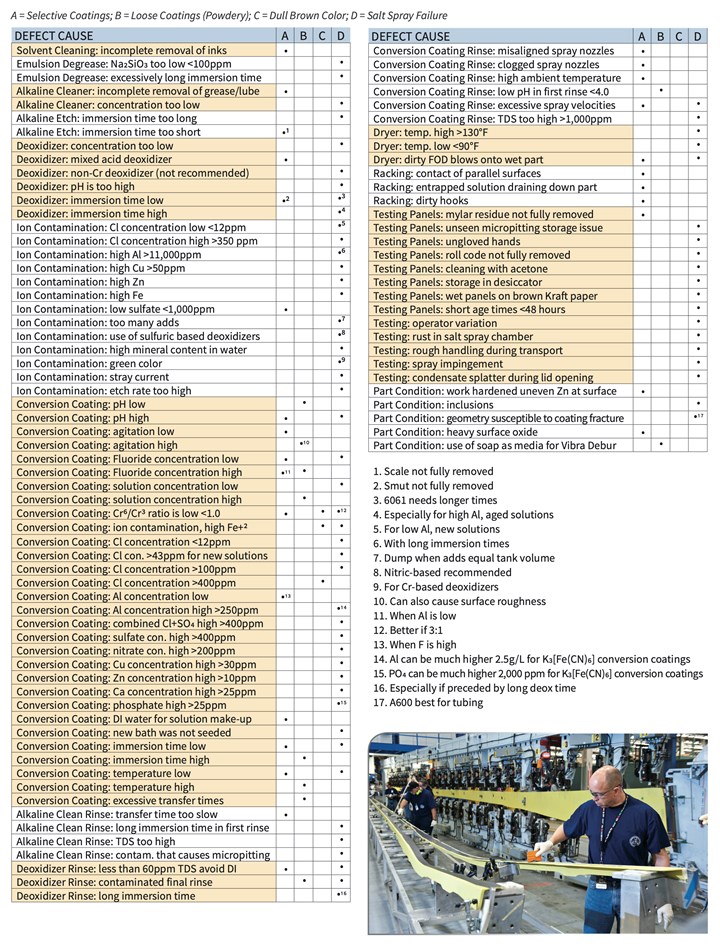 The purpose of this paper is to categorize causes and provide a supplemental troubleshooting guide matrix in XI. Appendix A (download here) that is organized by process steps such as cleaning, deoxidizing, conversion coating, rinsing and drying. Additionally, other factors are included such as: racking, testing and part condition. This topic has been studied extensively. Where possible, quantitative values are provided but are not intended to be considered as a substitute for process specification requirements.
II. Pre-cleaning
Often the initial step in any chemical finishing process is to ensure that the work surface is free of soils, lubricants, oils and foreign contaminants that could potentially be hydrophobic and impede the ability of the work surface to wet or react uniformly. Cleaning can be performed using solvents, emulsifying soaps and etching or non-etching alkaline cleaners.
The further removed or up-stream operations are from the conversion coating process step, the less likely a conversion coating problem is to occur. However, if the solvent cleaning or alkaline cleaning step is ineffective at removing organic contaminants, the operative result is that the part is partially “masked” by the unremoved organic soil and will result in a blotched or streaked appearance.
When needed for removal of inorganic contaminants, such as heat treat scale, an alkaline etch cleaner can be used. Early reports3,4 discouraged the use of these types of cleaners because test results at the time showed that aluminum products that had been etched, either by alkaline or acid, exhibited a higher rate of failure when subjected to salt spray testing in accordance with ASTM B117. This is generally thought to be the result of exposing more of the insoluble alloying elements in the aluminum by etching, thus providing more potential sites for corrosion to appear. This may be particularly true for high copper alloys, but it can also be the case with other alloys not associated with high copper.5 However, process optimization (reduced immersion time) has made the use of alkaline etch-cleaners commonplace for surface finishing pre-treatment prior to conversion coating.
For a variety of environment and health related reasons, vapor degreasing has been replaced with emulsion degreasing. If the emulsion degreaser is operated at a mildly alkaline pH (10.0-11.5), then a corrosion inhibitor constituent is needed and oftentimes is comprised of sodium meta-silicate (Na2SiO3). If the concentration of this constituent drops below 100 ppm, micro-pitting could result, which would negatively impact the salt spray performance.6 In extreme cases, all the corrosion inhibitor constituents can be lost if the water-based emulsion degreaser is exposed to freezing temperatures during shipment. If not noticed when the drum is opened, it will certainly be noticed if parts are processed. They will come out with a thin coating of black smut. Also worth noting is that excessively long emulsion degrease immersion times should be avoided.7
III. De-oxidizing
The main purpose of a deoxidizer prior to chemical conversion coating is to remove the native passive aluminum oxide layer to expose the underlying reactive aluminum, thus preparing the surface to react with the conversion coating solution. The deoxidizer removes the surface alloying elements to improve the corrosion resistance of the conversion coated aluminum. The deoxidizer may also remove any remaining alkalinity or organics and ensure a uniformly wet surface without water breaks.
De-oxidizing – non-uniform selective coatings
Most aerospace companies use nitric based deoxidizers as the acid source, since the alternative sulfuric acid deoxidizer can result in drag-out to the conversion coating tank and “poison” that solution.3 To counter that effect, processors using sulfuric acid-based deoxidizers require very clean deoxidizer rinses to avoid drag-out of sulfate ions into the chromium conversion coating solution. This “very clean” deoxidizer rinse, can then unintentionally passivate the freshly deoxidized surface and also cause non-uniform selective or “streaky” coatings due to a lack of ions in the very clean rinse. Processors using deionized water rinses are allowed to add an ionizing salt such as sodium sulfate to the final deoxidizer rinse in the concentration range of 15-50 ppm to improve coating uniformity.8
For nitric based deoxidizers, streaky coatings have been remedied by adding ~1000 ppm sulfate to the deoxidizer solution.3 Furthermore, long transfer times between the deoxidizer and deoxidizer rinse can result in streaky coating appearances.9
For operations where an alkaline etch solution is used, care must be taken that the following deoxidizing step fully removes the formed smut layer. Partial removal usually happens if the deoxidizer immersion is too short. This is difficult to immediately detect since a water-break-free surface can still be achieved. This situation can also result in blotchy coatings as well as possible paint adhesion failures.4,5 To determine the effectiveness of the deoxidation solution, one can experiment by manually abrading the surface of a test piece made of the same alloy material. If the panel has uniform color development, it is a good indication that the deoxidizer is not fully removing the aluminum oxide layer.
De-oxidizing - salt spray failure
There are many causes related to the deoxidizing process that can contribute to salt spray failure. One of the hard lessons to be learned is that use of iron-based deoxidizers is directly attributable to poor salt spray performance.10 This effect is thought to be related to drag-out of deoxidizer into the conversion coating solution resulting in an excess of ferrous iron (Fe+2). This contaminant could then form a colloidal suspension with the potassium ferricyanide components (K3Fe(CN)6) of the conversion coating solution and inhibit that compound’s ability to act as an initiator. Specifically, the ferrous ion contamination contributes to early depletion of Cr(VI) by a simplified redox reaction of:
3Fe(II) + Cr(VI) → 3Fe(III) + Cr(III)
This reaction lowers the conversion coating Cr(VI)/Cr(III) ratio, which is also known to be associated with salt spray failure and can possibly result in a dull brown color on the part or panel surface. The ferric sulfate, in iron-based deoxidizers, will also oxidize the cuprous (Cu+1) residue that develops on aluminum after alkaline etching, to cupric (Cu+2) sulfate. The cuprous form is insoluble, whereas the cupric form is soluble. As part of the reaction, the soluble ferric will convert to the insoluble ferrous; the purpose of nitric is to convert the ferrous back to ferric allowing it to continue oxidizing the copper.
Fe(III) + Cu(I) → Fe(II) + Cu(II)
Fe2SO4 + Cu2SO4 → 2CuSO4 + 2FeSO4
In addition, nitric acid can deoxidize the aluminum, but it will be consumed very quickly. The ferrous iron that is not converted back will settle in the tank, or be circulated as insoluble particles, and if enough of this material is present, it will carry over to the rinse tank. If the rinse is not properly maintained it will carry over to the conversion coating tank, affecting salt spray performance.
Furthermore, if sodium sulfide (from the alkaline etch solution) is allowed to enter the iron based deoxidizer solution, the dragged-in sodium sulfide contaminant will compete with the ferric sulfate constituent of the iron-based deoxidizer. The sodium sulfide is not as strong an oxidizing agent and will not convert as much cuprous to the soluble cupric, thus allowing copper to remain on the surface of the aluminum and ultimately negatively affect salt spray performance of the conversion coating.
These mechanisms are outlined in some detail to explain why iron-based deoxidizers are not recommended for use in a conversion coating tankline.
Deoxidizer concentration is best to be targeted mid-range. Deoxidizer concentration that is too low can cause incomplete smut removal (if preceded by an alkaline etch) and the solution could then have too high a pH, which is thought to lead to salt spray failure.10 Furthermore, a concentration that is too high could lead to too high an etch rate which could then negatively contribute to intergranular attack.10 This is also the reason why nitric acid-based deoxidizers are preferred over sulfuric acid-based deoxidizers.4
The effect of too short a deoxidizer immersion time was already mentioned above in reference to non-uniform selective coatings. Additionally, the effect of too long a deoxidizer immersion time can be exacerbated when the deoxidizer aluminum levels start to climb above 11,000 ppm.4,11,12,13 This well-documented condition is the reason why an established immersion time can work well for months or even years (depending on part throughput) and then suddenly salt spray failures occur. Through designed parametric studies, it was also determined (at Boeing) that a process combination to avoid is a long deoxidizer immersion time followed by a long deoxidizer immersion rinse time.
Deoxidizer ion contamination has multiple anions and cations that can contribute to salt spray failures. The ion that should be on top of the watch list is chloride. There are many studies4,10 that have reported a maximum chloride concentration ranging from 25 ppm to 350 ppm. Another reason why iron-based deoxidizers should be avoided is that they are extra sensitive to chloride contamination.14 However, a fact not widely known is that new deoxidizer solutions having zero or very low levels of chloride (<12 ppm)10 can also result in salt spray failures. Therefore, the use of DI water for deoxidizer solution make-up is not recommended.
Other cations on the watch list would be copper, iron and zinc.4 These deoxidizer contaminants can come from alloying elements in the aluminum parts or from degrading tankline support structure, auxiliary equipment or fallout from overhead rails during crane movement. No specific high levels are noted for iron and zinc, however for copper, it is reported that the maximum level should be less than 200 ppm for chromium deoxidizers.15 Whereas it was already noted that tap water is preferred for make-up water, high levels of tap water mineral content should be avoided.4
Although not common, stray currents (~40 milliamps) have been observed in conjunction with the flight bars and the deoxidizer tank, causing salt spray failure. This condition can be remedied by replacing metal saddles with plastic saddles.16
For deoxidizer solutions, a process control rule of thumb worth noting is that when the quantity of additions equals the volume of the tank, a complete tank dump is likely due.4
IV. Chromium conversion coatings
As a result of past innovations, chromium conversion coating technology is exceptionally versatile, allowing application by immersion, spray, or rolling. Conversion coatings can be compatible with a wide range of aluminum alloys. The conversion coating chemistry is complex but the solution itself has proven to be rather robust, with most solutions lasting many years if maintained and monitored. Nonetheless, hexavalent chromium is a known and regulated human carcinogen and its use is accompanied by intense scrutiny from both the public and private sectors. As a result, efforts to find, identify and implement replacement technology have been ongoing. However, there is no frontrunner technology poised to broadly replace chromium in conversion coatings17.
Trivalent chromium conversion coatings are poised to bridge the gap until a chromium-free coating technology is proven. Despite being challenged by corrosion performance on high copper-containing alloys, trivalent chromium conversion coatings are becoming widely available.
Chromium conversion coating – non-uniform selective coatings
For new solutions, where the aluminum concentration is low, a high fluoride concentration can cause “blotchy” coatings. Using DI water for conversion coating solution make-up can also contribute to poor color formation.18
For aged conversion coating solutions, a low Cr(VI)/Cr(III) ratio (<1.0) can result in selective coatings. The conversion coating solution should target chemistry conditions of middle to high fluoride concentration and low to middle pH values from the ranges recommended by the process specification or product technical data sheet. Process parameter adjustments that could alleviate “streaky” coatings include increasing the solution agitation and maintaining consistent solution temperature. Conversion coatings are typically run at ambient temperatures and might not even require temperature controls on the tank. During winter, if the shop area is quite cold, the ambient temperature of the conversion coating solution might become cold enough to cause selective coatings, especially if combined with a short immersion time.
Streaky or blotchy color development can also be the result of an inactive surface which was not adequately deoxidized. See the section above on deoxidizing.
Conversion coating - loose (powdery) coating
A poorly adherent coating can be the result of allowing the conversion coating layer to become too thick. The conversion solution reacts with the metal surface, building a coating, but it is self-limiting. If work is allowed to process beyond the period of surface coating formation, the solution will continue to deposit, creating a loose layer on top of the adherent coating. If work is allowed to contact the solution for extended process times, the acidic conversion solution may begin to attack the newly formed conversion coating.
Loose or powdery conversion coatings can result in poor paint adhesion. Thus, failing paint adhesion can be one indication that the conversion coating process is less than optimum. Powdery coatings can be caused by a solution that is too “aggressive,” such as when the pH is low, the concentration is high and the fluoride concentration is high.4,13 A loose coating can also develop when process parameters such as solution agitation, temperature and immersion time are high. The opposite conditions and process parameters can result in selective coatings, which is why targeting mid-range for these chemistry and process parameter controls is imperative.
Conversion coating - salt spray failure
In general, chromium conversion coatings become more reliable at passing salt spray corrosion testing as they age, and solution replacement should be avoided when troubleshooting performance problems. If a chromium conversion coating solution must be completely discarded, it is advantageous to retain a portion of the old solution as a “seed” of built-up suspended particles of insoluble salt. K2NaAlF6, is theorized to draw newly etched aluminum ions from solution which helps extend tank life. A commonly used amount of seed is 25-50% of the bath solution. However, if old solution is not an option because of contamination, the use of 2024 bare aluminum sheet stock to artificially age the new solution can be considered.15,22
The chemical constituents of the conversion coating solution that affect salt spray performance are those that would predominantly cause low coating weights, such as low fluoride concentration, low solution concentration and high pH. One of the more common causes of salt spray failure is when the Cr(VI)/Cr(III) ratio is low. This condition can be indicated if the solution exhibits a green hue.4
The process parameters contributing to low coating weights are short immersion time and low temperature.4 It is a balancing act to maintain the chemical concentration of the conversion coating solution so it does not drift too far one way or the other, causing problems. Conversion coatings will also perform differently depending on the metal alloy. For instance, in one study,12 alloy 6061 was determined to perform best if the conversion solution was operated at the lower pH range and at a low to mid-range for concentration.
There is a broad spectrum of ionic contaminants to avoid that can cause salt spray failures. Cation build-up can occur as a result of alloying elements such as copper over 30 ppm19 and zinc over 10 ppm.4 Iron contamination was mentioned earlier as being detrimental to conversion coatings. It can contribute to lowering the Cr(VI)/Cr(III) by a simple redox reaction shown in section III. De-oxidizing of this paper. Even when a non-iron based deoxidizer is being used, iron contamination can result from old piping or auxiliary equipment that is slowly rusting. A less common cation contaminant is calcium, which should be kept below 25 ppm.
There are also numerous anionic contaminants in a conversion coating solution that can cause salt spray failures. Chloride is of most concern and there is a range of recommended maximum concentrations from a low of 25 ppm to a high of 350 ppm.4,9 Another important anion concentration limit is the combination of chloride and sulfate at 400 ppm.20 However, there are other studies that discuss the combination of chloride and sulfate that recommend ranges of 175 ppm21 to 800 ppm.4 Phosphate has been noticed to be problematic depending on the conversion coating type. Conversion coating solutions that have the potassium ferricyanide constituent are more forgiving and can tolerate a phosphate concentration of up to 2000 ppm.12 Conversion coating solutions that do not have that potassium ferricyanide constituent can only tolerate a phosphate contamination level of up to 25 ppm.10,22
It is not as well known that new solutions are more sensitive to chloride contamination (>43 ppm) than solutions that have been well used and have an appreciable aluminum ion concentration. It is interesting to note that in past studies, a minimum chloride concentration (12 ppm) was seen as beneficial. This narrowed range (12-43 ppm) of chloride for new solutions emphasizes why it is important to consider “seeding” a new solution with an old solution.9 The recommended “seed” amount is to keep at least 25-50% of the old bath when making up a new solution.15,22 Disregarding this seeding recommendation can lead to unpredictable salt spray failures when re-qualifying the bath.
V. Rinses
Dedicated rinse tanks are most commonly interspersed between each process solution and ideally are not shared. Furthermore, a best practice is for the rinse system to be comprised of a double-counter current system if immersion rinsing, where typically fresh water is pumped into the bottom of the final rinse tank and overflows into a weir that is fed into the bottom of the first rinse tank. The first rinse tank overflow is then either recycled or sent out as wastewater. Another option is to utilize a single immersion rinse followed by a spray rinse tank. Water quality of the final rinse should be periodically tested and maintained to meet the requirements of the process solution the rinse services. Water usage can be determined by the need to sustain the process requirements and can be predetermined by use of a publicly available rinse water reduction calculator.23
Rinses - selective coatings
Long transfer times (movement of the load from one tank to the next) in general should be avoided. However, that is particularly true for rinses that follow alkaline clean process solutions. These rinses are often heated, and inadvertent drying of the rinse water can result in conversion coating streaking. This is caused by the part surface being lightly masked by residual cleaner going into the deoxidizer tank. The slightly masked part surface will unevenly deoxidize, and if part surfaces have been selectively deoxidized, they will then take on the conversion coat unevenly which will exhibit a streaked appearance.
It is well known that rinses following the deoxidizing process solution can be too clean, resulting in passivation of the freshly deoxidized surface and conversion coating streaking. A Boeing process specification18,20 provides a note to that effect stating that:
“Rinses that contain less than 60 ppm total dissolved solids (TDS) following nitric acid based deoxidizers, may inhibit localized color development of subsequent chemical conversion coatings.”
For the rinse that follows the conversion coating process solution, conditions to watch for are:
- Spray rinses that have misaligned or clogged nozzles.
- Spray rinses where the water pressure is too high potentially damaging the still soft conversion coating.
- Ambient temperatures that are too high.
A fresh conversion coating having not yet been dried is subject to uneven or aggressive spray rinsing. Additionally, if the rinse after Alodine is too warm, unintentional leaching of chromates can occur.4
Rinses – loose (powdery) coating
Rinses that follow the deoxidizer process solutions that are highly contaminated can result in the formation of loose coatings. Consequently, the final rinse following the deoxidizer step should be controlled at less than 750 ppm.
The first rinse that follows the conversion coating process solution can cause loose coatings if it is too acidic. This is why the Boeing Process Specification20 requires that the first rinse have a pH above 4.0.
Rinses - salt spray failure
Salt spray failures caused by poor rinsing conditions are generally due to micro-pitting of the part surface. The first rinse following an alkaline cleaner is still high in pH and can be over the pH range in which aluminum needs to have corrosion inhibitors for protection from selective alkaline etching at the micro-structure level. Consequently, long immersion times in a first rinse following an alkaline cleaning process solution should be avoided. The final rinse following an alkaline cleaning process solution also needs to be monitored for cleanliness and usually has a requirement to be maintained at less than 750 ppm total dissolved solids.
Deoxidizing rinse process conditions that cause selective coatings can also result in salt spray failure. This is the case when rinse water is too clean after deoxidizing. Additionally, deoxidizer process conditions that result in loose coatings can also cause salt spray failures. This is the case if the final deoxidizer rinse is heavily contaminated with dissolved solids. As mentioned in III. De-oxidizing, it is worth repeating that a process combination to avoid is a long deoxidizer immersion time followed by a long deoxidizer immersion rinse time.
Some process conditions of rinses, following the conversion coating process, that can cause loose coatings, can also cause salt spray failures. In practice, this has been observed to be the case for spray rinses that have excessive velocities, thus adversely impacting the fresh conversion coating that has not yet had a chance to dry and harden. Furthermore, the final rinse can cause salt spray failures if it is highly contaminated, which is why the Boeing Process Specification20 has a recommendation for the final conversion coating rinse to be monitored and maintained at a TDS level of less than 1000 ppm.
VI. Drying
Drying is the last step in the conversion coating tankline process. Heated dryers that are dirty have been noted4,13 to contribute to blotchy conversion coat appearances, likely due to foreign object debris being blown onto the soft amorphous conversion coating surface.
It is well known3,11,16,24,25,26 that too warm a dryer temperature (>160°F) or a longer27 dry time than needed will instigate a mud-cracking phenomenon of the conversion coat surface, which then gives a salt spray solution easy access to the unprotected aluminum surface. As the conversion coating dries, it loses water. The chromium oxide dehydrates according to the following reactions:
Cr2O3•3H2O → Cr2O3•H2O + 2H2O, or
Cr2O3•3H2O → Cr2O3•2H2O + H2O
Thus, too high a temperature causes the film to break down or dehydrate. The Boeing Process Specification limits the drying temperature to 130°F,20 If the chromate film is not properly cured, then water from the salt spray penetrates the coating and leaches out the chromates.
Not as intuitive is that too low a dryer temperature (<90°F) can also cause salt spray failures.22 Perhaps, low dryer temperatures do not allow the newly formed amorphous gel coating to properly coalesce prior to salt spray testing.
VII. Racking
Process equipment and techniques such as racking can cause part surfaces to have unacceptable conversion coating streaking. Racking parts or panels too close together can result in the flat part surfaces contacting each other and thus creating poor process solution exposure and poor rinsing conditions.
The condition of the racks themselves can cause streaking, such as when the hooks are not maintained and become dirty4 or if the rack design allows process solution to be entrapped and run down the parts when in flight between rinse tanks or to the next process step.
VIII. Testing
It is not uncommon that the conversion coating process is healthy, but the test conditions themselves can lead to erroneous failures and bewildering observations.
Testing - selective coatings
Test panels are often protected in storage with a Mylar cover. On one noted occasion, panel streaking was observed when part processing was unaffected. The determined cause was that a bad batch of specimens, where Mylar residue remained on the surface after the Mylar film was removed. This was perhaps due to specimens being:
- Stored too long
- Storage conditions being exposed to high ambient conditions
- A bad batch of Mylar film
Testing – salt spray failure
There have been many documented situations of test panel conditions that have resulted in false failing results such as:
- Segregated copper or silica rolled onto the surface of the test panel material surface at the mill that may not be removed by chemical methods.4
- Surface of test panels subject to corrosion are oftentimes the result of:28
a. Age
b. Improper storage
i. Wet panels placed on brown Kraft paper can leach sulfuric acid onto the panel.6
c. Storage in a desiccator
d. Improper handling (such as touching panels with ungloved hands).4,25
3. Improper cleaning of test panels may cause salt spray failures as a result of:
a. Roll code that is not completely removed.
b. Solvent cleaning with acetone may cause micropitting.
- Test panels that are not allowed to age after conversion coating are known to cause Salt Spray failures (48 hours minimum is needed, over a week is better.).25
The test process and conditions inside the salt spray chamber have also been known to be the cause of false failures such as:
- Observed rust in the salt spray chamber.4,15
- Too aggressive spray impingement pressure.29
- Condensate splatter during salt spray chamber lid opening.30
Finally, inexperienced operators can inadvertently cause failures due to rough handling during specimen transport or even inaccurately judge specimens.4
IX. Part condition
The preceding section discussed adverse conditions to be aware of for the test panels, likewise there have been documented situations to be aware of for the incoming condition of the parts being processed.
Part condition – selective coatings
For 7075 aluminum alloy parts that are work hardened, this process can sometimes result in uneven zinc at the surface layer, which in turn will cause a blotchy appearance on the part surface. Another documented cause for blotchy appearances on the part surface are due to incoming heavy surface oxides, where the selected deoxidizer is unable to remove the oxide uniformly.13
Part condition – loose (powdery) coating
Some smaller parts are sometimes subject to a Vibra-Debur process that involves the use of media that is comparable to a powdered detergent cleaner. There has been some documentation31 that inconsistencies in the Vibra-Debur process can result in powdery coatings. Plastic is the preferred vibratory media for aluminum parts.
Part condition – pitting
Although, of course, parts do not go through a salt spray test, there are incoming part conditions that can result in part pitting. Heavily machined parts are subject to micro-inclusions that cannot be seen readily without magnification. These micro-inclusions, however, are revealed during the tankline process where pitting occurs at the inclusion site due to a standard galvanic process.
Part condition - geometry
Part geometry has been a documented cause of primer film fracturing. In one study,33 it was learned that Alodine 600 was preferred over that of Alodine 1200S for tubing because Alodine 600 was noted to lead to less coating fracture due to the difference in coating weight.
X. Summary
The purpose of this paper was to identify the defects of:
- Uneven coatings (streaks, blotches)
- Dull brown color
- Loose coatings (powdery)
- Salt spray failure and then categorize causes of failure.
A supplemental troubleshooting guide matrix XI. Appendix A is provided and organized by process steps such as cleaning, deoxidizing, conversion coating, rinsing and drying. Additionally, other factors are included such as: racking, testing and part/specimen condition. This topic has been studied extensively.
The intended use of this paper then is to aid processors with a broad troubleshooting tool when conversion coating failures are encountered.
XI. Appendix A


References
1. J. Anthony, “New Surface Treatment for Aluminum,” Iron Age, 158 (23), 64-67 (1946).
2. ASTM Standard B117-18, “Standard Practice for Operating Salt Spray (Fog) Apparatus,” ASTM International, West Conshohocken, PA, 2018, www.astm.org.
3. Department of the Navy report, NADC-75125-30, 1975.
4. Boeing Quality Control Research and Development Report, (QCRDR) HF310A, 1984.
5. L. Chesterfield, “Etching Prior to Chromate Conversion Coatings”, Products Finishing post, 8/1/2006.
6. W.J. Fullen & J. Deheck, “Aluminum Surface Finishing Corrosion Causes and Troubleshooting,” PF Online, 10/17/2014; https://www.pfonline.com/articles/aluminum-surface-finishing-corrosion-causes-and-troubleshooting.
7. Process Specification, BAC5763 - Emulsion Cleaning and Aqueous Degreasing.
8. Process Specification, BAC5765 PSD 9-11 - Cleaning and Deoxidizing Aluminum Alloys.
9. Boeing SR/PA 632-100, 1978.
10. Boeing Memo 6-4620-F1-98024, 7/29/1998.
11. Boeing Quality Control Research and Development Report (QCRDR) F181RE, 3/24/1982.
12. Boeing Manufacturing Development Report (MDR) 2-46075, 1/2/1990.
13. Boeing Manufacturing Development Reports (MDR) 2-26816/2-36010, 2/18/1970.
14. Boeing memo 6-3020-11-162, 5/20/1981.
15. Metal Finishing, 89 (12), 13-14 (1991).
16. Boeing Manufacturing Research & Development (MR&D) Activity report, April 1997.
17. R.G. Buchheit, “Conversion Coating Science and Technology -Is It Still Evolving, or Is It Stuck?”, Fontana Corrosion Center, Ohio State University, Columbus, OH; https://www.electrochem.org/dl/ma/201/pdfs/0279.pdf.
18. Manufacturing Development Report (MDR) 2-36342, 8/31/1982.
19. Boeing memo 6-4620-11-97JF08.
20. BAC5719 - Chemical Conversion Coatings for Aluminum and Aluminum Alloys.
21. Manufacturing Development Report 2-46905, 8/25/1989.
22. Boeing memo 6-4620-F1-99030.
23. J.K. Unangst & W.J. Fullen, Plating and Surface Finishing, 91 (12), 44-49 (2004)
24. Boeing Operations Technology Development Report 6-03217, September 1995.
25. Boeing Memo A-2020-11-237, 11/11/1983.
26. Department of the Army Report A66-23, August 1966.
27. Boeing Manufacturing Development Report, 2-36004, 9/17/1973.
28. Metal Finishing, 89 (10), 45-47 (1991).
29. H.R. Friedberg, “Why Use the Salt Spray Test?”, Steel, 135 (5), 76 (1955).
30. Boeing Quality Control Development Report (QCDR) 242-803, 1/16/1975.
31. Boeing Memo A-2020-20-937, 7/12/1988.
32. W.J. Fullen, “Troubleshooting Salt Spray Failures: Tried-and-true techniques help users make quick decisions on corrective actions for anodized aluminum structures,” Metal Finishing, 104 (12), 12-17 (2005).
33. Boeing Operations Technology Development Report (OTDR) 6-03176, 2/13/1992.
About the authors
.jpg)
Gail F. Stribling Geldien is a chemical engineer with Boeing Research and Technology. She supports the Fabrication Division in Auburn, Washington to improve chemical manufacturing processes. Previously, she performed research for inorganic finish development and corrosion prevention. Gail holds a B.S. in Chemical Engineering with an emphasis on biochemical processing from Oregon State University.

W. John Fullen has been with the Boeing Company for 34 years, at present in the Boeing Research and Technology (BR&T) organization, first in advanced composites but predominantly in chemical technology in support of tankline operations and the Boeing supply base. Prior to that, he worked at H.B. Fuller Co. in the area of adhesives. He holds a B.S. in Chemical Engineering from the University of Minnesota.
* Corresponding authors:
Gail F. Stribling Geldien MC: 5K-60
W. John Fullen MC: 5A-203
Boeing Research and Technology
The Boeing Company
P.O. Box 3707
Seattle, WA 98124-2207
Email: Gail.F.StriblingGeldien@boeing.com
Email: Warren.J.Fullen@boeing.com
RELATED CONTENT
-
Defects in Hard Chromium Deposits Part I: Causes and Cures
The causes of and remedies for defects in hard chromium deposits are explored in the first of this two-part P&SF article from 1984. Photomicrographs and SEM (scanning electron microscope) photographs will illustrate that most defects in various hard chromium deposits arise from defects in the basis metal. These defects may be in the original metal surface or may be caused by preplate finishing. Homogeneous hard chromium deposits can be produced only by eliminating these defects. Practical suggestions and procedures will be given.
-
Black Chromium Finishing: Beauty and the Beast
Over the past 10 years, there has been commercial development of black chromium deposits from a trivalent chromium electrolyte. This paper will review the deposit characteristics and operational consideration of these similar, but different chromium plating deposits.
-
Electroplated Tin-Nickel Coatings as a Replacement for Nickel to Eliminate Nickel Dermatitis
This paper is a peer-reviewed and edited version of a paper delivered at NASF SUR/FIN 2013 in Rosemont, Ill., on June 12, 2013.


