
A Novel Surface Finishing Technology for Alloys
A paper* based on a Presentation given at NASF SUR/FIN 2022 (Rosemont, Illinois) by
Chris Goode**
Cirrus Materials Science Ltd.
#surfin
Share
A paper* based on a Presentation given at NASF SUR/FIN 2022 (Rosemont, Illinois) by
Chris Goode**
Cirrus Materials Science Ltd.
Auckland, New Zealand
Editor’s Note: The following is a paper based on a presentation given at NASF SUR/FIN 2022, in Rosemont, Illinois on June 8, 2022, in Session 7, Decorative Automotive Considerations. A pdf of this brief can be accessed and printed HERE.
Featured Content


ABSTRACT
This paper offers an introduction to a low‐voltage, non‐toxic Plasma Electrolytic Oxidation (PEO) coating technology for application to magnesium. Cirrus Mg Defender™ is a novel surface finishing technology that provides thin, adherent, and durable protection for magnesium and its alloys at low cost with an exceptionally low energy and environmentally sustainable process. The technologies presented here include the new Cirrus Guardian™ which extends the low power PEO process to aluminum and titanium substrates.
Introduction
Cirrus is a New Zealand company that focuses on developing innovative surface finishing technologies. Our customer base is technology end users with surface finishing problems for which Cirrus technologies add value. A recent surface finishing innovation from Cirrus Materials Science, Mg Defender™, offers a sustainable magnesium coating technology that reduces the cost, energy consumption and coating thickness required to protect magnesium components.
Cirrus Mg Defender™ employs a proprietary low voltage Plasma Electrolytic Oxidation (PEO) process to deposit a tightly bonded protective layer to any magnesium surface. Cirrus Mg Defender™ operates at less than 5% of traditional PEO process power while producing a surface that provides outstanding corrosion protection. Doping the Mg Defender™ bath with either carbon and/or nitrogen compounds which, under the influence of the arc temperatures introduce carbides and/or nitrides directly into the developing surface, achieves surfaces with higher hardness (>875 HV) and greater wear resistance. These surfaces also support direct deposition of secondary functional coatings including electro- or autocatalytic metallic coatings and electrodeposited or traditional polymer surfaces, which tightly interlock to the PEO surface producing outstanding adhesion. Such secondary layers can provide important functional characteristics, including electrical conductivity, wear resistance, lubricity and/or decorative aspects, which support a plethora of applications. This paper provides an update on this novel magnesium coating technology which extends the opportunities for magnesium applications.
Background
The genesis of our light metal PEO technology was in the Cirrus Hybrid technology and process. In 2016, Cirrus developed this efficient coating process that combined anodizing and electrolytic or autocatalytic plating to provide conductive protective surfaces on aluminum substrates. This process significantly lowered both the energy and time required to deposit protective coatings on a wide range of aluminum alloys. The attributes of the hybrid process make it widely applicable. However, while the Cirrus Hybrid process supported anodizing and electroplating hybrids on aluminum and titanium surfaces, protecting magnesium proved more challenging due to the absence of regular pore structure in the magnesium anodized surfaces.
To answer the magnesium hybrid challenge, we first evaluated coatings using an existing PEO technology as a replacement for the anodizing process step. We discovered, however, that this process was neither energy efficient nor produced surface morphology that would support the subsequent electrodeposition of conductive metal surfaces.
In 2019, Cirrus commenced researching new bath chemistries that might overcome the existing technology limitations. In this we were successful and developed a non-toxic bath that was sufficiently conductive to create PEO surfaces at relatively low voltages. Our bath and process utilized no toxic chemicals and was able to efficiently build magnesium silicate/oxide surfaces at room temperature using very low power.
The process
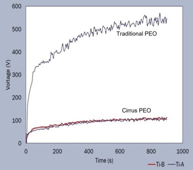
Figure 1 – Voltage-time curves comparing traditional PEO process operation with Cirrus technology.
Figure 1 shows a voltage-time curve for a PEO deposition bath using both the Cirrus technology and a more traditional PEO process. The Cirrus process power consumption is about 10 watts per micron per square decimeter. The graph shown here is from a PEO a process on a titanium substrate, but the voltages are similar for both aluminum and magnesium substrates. However, in each case, slightly different current densities are required. One notable advantage of our PEO process is that it operates in a room temperature bath. Thus, the process energy savings comprise both reduced solution cooling power requirements and the lower intrinsic PEO power.
Anodized surfaces created with this new PEO process proved suitable for the subsequent deposition of adherent metallic surfaces, from sufficiently alkaline plating bath chemistries. Acidic chemistries attacked the magnesium substrate and spalled the PEO surface. However, functional metallic surfaces from acidic chemistries could be plated once an interstitial layer was deposited using an alkaline bath. The finished hybrid surfaces were typically aesthetically pleasing, conductive, had acceptable corrosion resistance, and supported deposition of functional to layers.
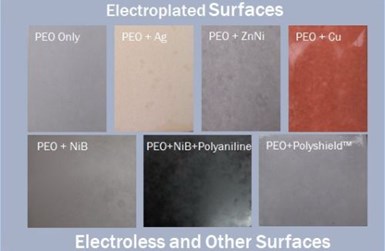
Figure 2 – Examples of hybrid surfaces produced over Cirrus PEO processing.
The images in Fig. 2 show some of the hybrid surfaces developed over the base surface produced by the new PEO technology. On the top right is a ZK60 magnesium substrate with a 10-micron PEO surface. The remaining images are of coatings on either are all ZK60, AZ80 or AZ91. The remaining top row images all have a variety electrodeposited metal surfaces over between 2 and 10 microns of PEO.
We have found that electroless nickel boron works well over the PEO layer and, from the middle bottom image, we have electrodeposited polyaniline over this to create a tough black surface. The electroless process requires a silver nitrate dip after the PEO to activate the surface before the electroless nickel boron. The lower right image is a PEO surface onto which we have deposited Cirrus PolyshieldTM coating. Cirrus PolyshieldTM is a unique surface-initiated polymer that develops a tough high molecular weight and low poly-dispersity index coating. This coating takes advantage of the photocatalytic nature of some PEO surfaces to initiate polymerization.
Suitable alkaline chemistries for initial deposits required a pH of above 9 and included copper, silver and electroless nickel-boron. The PEO surfaces support direct deposition of electrolytic coatings. However, electroless deposits required seeding the surface using a silver nitrate dip prior to immersion in the electroless bath. In all cases the surfaces produced were conductive through to the substrate with an effective resistance of about 20 milli-ohms per square inch at 1.0 A.
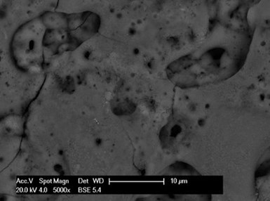
Figure 3 – SEM photo of PEO microporous morphology.
The secret to depositing all these metallic coatings successfully is the micro-structure of the PEO layer. The SEM photo in Fig. 3 shows that the Cirrus PEO surface has a typical basaltic microporous morphology. These surface pores penetrate or partially penetrate the PEO layer allowing the deposition of well interlocked metallic layers.
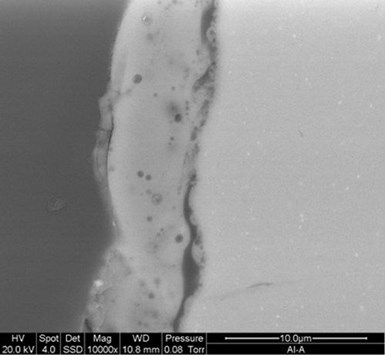
Figure 4 – Cross-sectional SEM image of the Cirrus PEO layer.
The SEM in Fig. 4 shows a cross section of a 6-micron PEO surface deposited in about 8 minutes, demonstrating a build rate of about 1 micron per minute. The image shows the thin oxide barrier layer which is essential to supporting electrodeposition of metallic surfaces. The compact but relatively porous oxide silicate PEO coating can also be seen.
During the last two years, we extended our low voltage PEO technology, creating a single bath chemistry that could deposit PEO coatings on magnesium, aluminum and titanium alloys, referred to as Guardian™ technology.
Aminophenol additives

Figure 5 – Effect of aminophenol additives in the PEO process on Ti, Mg and Al substrates.
One interesting characteristic of the new chemistry is its ability to incorporate nitrides and carbides compounds as nano-domains within the PEO surfaces. The addition of small quantities of aminophenols, or other nitrogen/carbon containing compounds, to the PEO bath develops these hard inclusions. We have experimented with other bath additives, all of which show the ability to integrate novel functional compounds into the developing PEO surface. In general, the bath additives are broken down in the micro arcs and compounded with the metal from the substrate. The series of SEM images in Fig. 5 show comparative surfaces prepared on various substrates using a single bath chemistry. The top row shows titanium, magnesium and aluminum surfaces from the unenhanced bath, while the bottom row shows the surfaces deposited on the same substrates from a bath containing aminophenol additives. While all coatings all exhibit the typical basaltic morphology of PEO surfaces, the surfaces developed from the bath containing aminophenols are much less porous. We understand this to be due, in part, to the surfactant-like nature of the aminophenols, which reduces the size of the arc discharge bubbles, intensifying the plasma temperatures and pressures.
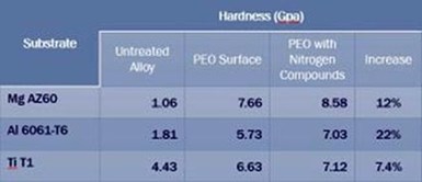
Table 1 - Nanohardness of magnesium, aluminum and titanium PEO surfaces (GPa).
Table 1 shows the nano hardness, in GPa, of magnesium, aluminum and titanium PEO surfaces developed, using the new process, from baths with and without aminophenol additives. As may be observed, a very small quantity of nitrides and carbides incorporated into the coatings from the aminophenol-containing baths engender sometimes significant improvements in coating hardness. The percentage improvement is proportional to the quantity of incorporated carbides and/or nitrides in the PEO surface, a function of arc energy. The bath conductivity and barrier layer breakdown voltage control the minimum voltage for the PEO process, while the current density controls the total arc energy. Here, the Ti and Mg processes operated at a current density of between 1 and 2 A/dm2 while the Al process was operated at 4 A/dm2. Doubling the current density means four times the arc energy and significantly higher carbide and nitride creation.
We have performed extensive analysis of the PEO surfaces to understand the structure and composition including SEM, Raman spectroscopy, XRD and XPS. The resulting data set is far too extensive for inclusion here. However, Figure 6 shows the deconvoluted Raman results for a titanium PEO surface created from a bath with and without aminophenols, and a table identifying the source of a subset of the significant peaks identified.

Figure 6 - Deconvoluted Raman results for a titanium PEO surface created from a bath (a) with and (b) without aminophenols and a table of the significant peaks.
In Fig. 6(b), the Raman Shift peaks for titanium carbide and titanium nitride at 515 and 570, respectively, are shown (inset). While the Raman analysis suggests that these peaks could be either metal oxy-silicates or metal carbides and nitrides, XPS analysis demonstrated the presence of both carbides and nitrides.
It is interesting to note that the presence of these compounds in a titanium PEO surface has the effect of lowering the optical band gap of the surface into the visible blue region offering potential opportunities for these surfaces to enhance the titania photocatalytic activity.
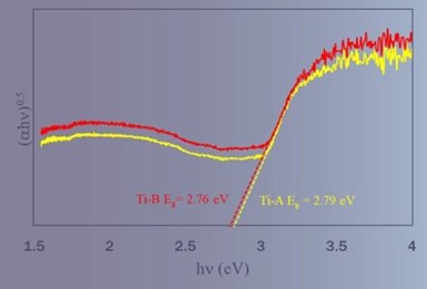
Figure 7 – Tauc plots for determining the optical band gap for PEO coatings deposited from solutions with and without aminophenol compounds.
Figure 7 shows Tauc plots obtained from the measurement of diffused reflectance spectra and analyzed to determine the optical band gap of the coatings deposited from baths with and without aminophenol compounds.
Titania typically exhibits optical bandgaps of between 3.1 and 3.2 eV compared with the ~2.78 EV shown here. While the baths without aminophenols also show reduced bandgap, it is worth noting that these baths contained other nitrogen and carbon bearing organics. We believe both this, and the presence of metal silicates are the reasons for the lower band gap exhibited from the bath without aminophenols.
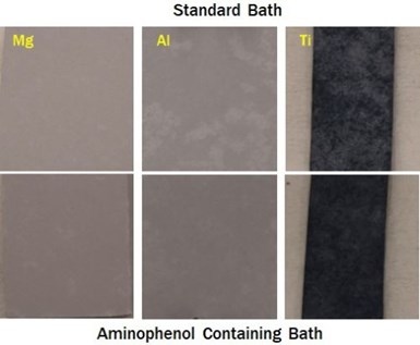
Figure 8 – Images of PEO surfaces deposited on Mg, Al and Ti, from baths with (upper row) and without (lower row) aminophenol.
Figure 8 shows a set of optical images of the PEO surfaces deposited on the various substrates. While overall, the PEO surfaces are smooth and defect-free, the bottom row images, showing coatings deposited from the aminophenol containing baths, appear to be more uniform. Testing of all PEO surfaces demonstrate that they initially exhibit super hydrophilic properties, with water contact angles of between 1 and 3 degrees, indicting the presence of surface nano/microstructures. This attribute enhances their paint ability and simplifies the deposition of further metallic layers, as previously discussed.
Carbon additives
The ability to include carbides and nitrides using a low voltage PEO initiated investigation of other functional materials that the arc process might incorporate into the surface. . The demonstrated ability to develop carbides suggested an exploration of graphene and reduced graphene oxide as bath dopants. Graphene oxide, due to its increased dispersibility in aqueous media, seemed the obvious choice. However, we finally focused our energy on graphene due to its increased availability. Shown in Figs. 9 and 10 are the coating changes engendered by adding graphene materials directly into the bath.
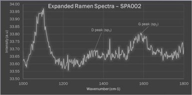
Figure 9 - Enlarged segment of a Raman spectrum of a PEO surface produced on a titanium substrate from a bath containing graphene oxide, identifying the potential sp2 and sp3 peaks.
There were two research question of interest. Firstly, could the low voltage PEO process effectively incorporate significant quantities of graphene into the PEO surface. Secondly, were the PEO arc temperatures and pressures sufficient to convert sufficient sp2 carbon to sp3 and develop surfaces with diamond-like properties.
Figure 9 shows an enlarged segment of a Raman spectrum taken from an early PEO surface produced on a titanium substrate from a bath containing graphene oxide. The plot identifies the potential sp2 and sp3 peaks. While this was a less than stellar result, it provided sufficient impetus to investigate further. Introducing significantly greater quantities of graphene nano platelets into the bath produced an interesting result.
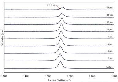
Figure 10 – A series of Raman shift curves of incremental 2-micron ablations thru a 15-μm PEO coating produced in a bath containing well-dispersed graphene.
The Ramen shift curves shown in Fig. 10 were produced by repeatedly making a measurement followed ablating 2 microns from the surface of a 15-micron PEO coating produced in a bath containing well-dispersed graphene. As shown, the graphene is uniformly distributed throughout the coating, albeit without significant conversion for sp2 to sp3 carbon forms.
Figure 11 shows the (a) optical and (b) SEM images of the 15-micron PEO surface on the T1-titanium alloy from which the Raman depth profile data in Figs. 9 and 10 was gathered. The surface is uniform and apparently very smooth to the touch. Our analysis suggests that the darker blue areas are those rich in graphene while the lighter areas are mainly titanium oxides and silicates. Despite the apparent smoothness of the surface the micro/nano structure, seen in the SEM image, the surface exhibits super hydrophilic properties, as suggested in Fig. 11(c) in which a 0.5-mL drop of DI water wicks over the entire sample surface producing a contact angle of much less than 5 degrees.

Figure 11 - (a) optical and (b) SEM images of the 15-micron PEO surface on T1-titanium alloy from the Raman spectra study; (c) hydrophilic properties of the surface.
Corrosion
A principal function of a PEO surface is to protect the underlying substrate from corrosion. We have conducted both electrochemical analysis of these surfaces and salt spray testing of the low voltage PEO surfaces.

Figure 12 – Tafel measurements for (a) raw and PEO treated surfaces on titanium T1 alloy and (b) raw Al-6061 substrate and the PEO surfaces produced without aminophenols (Al-A) and with aminophenols (Al-B).
Figure 12(a) shows Tafel measurement results for raw and PEO treated surfaces on titanium T1 alloy. In this case the 13-micron Ti-A coating was produced from a bath without aminophenols, while the Ti-B coating, produced from a bath containing aminophenols, was slightly thinner, 10 microns. There is a clear trend in the corrosion voltage between the raw substrate the Ti-A and Ti-B surfaces. The different thicknesses of the two PEO surfaces impacted the trend in corrosion current density, however by increasing the thickness of the Ti-B surface a corresponding corrosion current density trend should be obvious.
An identical trend is observed with the corrosion voltages between the raw Al-6061 substrate and the PEO surfaces produced without aminophenols (Al-A) and with aminophenols (Al-B)(Fig. 12(b).***
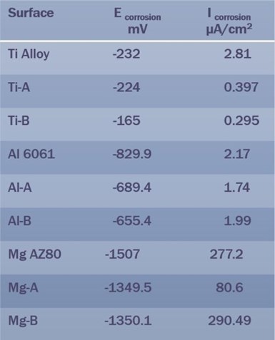
Table 2 – Summary of EIS data for Ti, Al and Mg PEO surface types.
Table 2 summarizes the electrochemical impedance spectroscopy (EIS) data for the three PEO surface types (Ti, Al and Mg). Here the magnesium data requires explanation. The PEO surfaces on which the measurements were made were relatively thin, between 2 and 6 microns, with the surface from the bath containing aminophenols being the thinner surface. Thus, while the corrosion voltages follow the trends seen for titanium and aluminum PEO surfaces, the corrosion current density for the Mg-B surface was higher than expected, due to the thinner coating. This result clearly demonstrates the relationship between coating thickness and corrosion performance, increasing the coating thickness to say 10-microns should significantly improve the corrosion performance. Of course, depositing a surface metallic or polymer layer would also improve the corrosion performance.
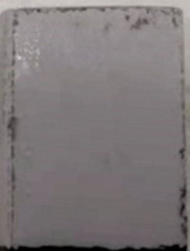
Figure 13 – Optical image of a 4-micron PEO surface on magnesium after deposition of 20-microns of Cirrus PolyshieldTM topcoat.
Figure 13 shows a 4-micron PEO surface on a magnesium substrate with approximately 20-microns of a Cirrus PolyshieldTM as a topcoat. Cirrus PolyshieldTM is a pure polymer surface tightly bonded to the activated PEO surface. The image was taken after more than 400 hours of neutral salt spray testing. The only observable corrosion is around the edges with no polymer deposits.
Cirrus has extensively evaluated the wet and dry adhesion of polymer surfaces on PEO surfaces using both pull of and scribe tests. These tests all demonstrate both outstanding adhesion and straightforward application of these topcoats due to the super hydrophilic surface and micro porous structure.
The PolyshieldTM surface requires hydroxyl radical initiation as it contains no other polymerizing agent. The PEO surface both has a sufficient density of active photocatalytic hydroxyl sites to directly initiate polymerization of the monomer.
Summary
There is an enormous number of applications of the low voltage PEO technology, some of which are represented in Fig. 14. Cirrus is currently focusing of the potential of the low energy PEO process to develop hard and wear-resistant surfaces as a replacement of conversion coatings on light alloy substrates. We have data that shows the process can introduce both corrosion inhibitors into the surface as well as high hardness carbon and nitrogen compounds. This may offer advantages over traditional conversion coatings, not only in reducing energy requirements but also in reducing application times and improving functional performance.

Figure 14 – PEO technology applications.
About the author

Chris Goode is a founder and Chief Technical Officer at Cirrus Materials Science Ltd., in Auckland, New Zealand. Chris holds an honors degree in engineering from the University of Western Australia. He holds over 30 patents and has extensive experience in multiple fields of engineering including telecommunications robotics and chemical engineering.
*Compiled by Dr. James H. Lindsay, Technical Editor - NASF
** Corresponding Author: Chris Goode, CTO, Cirrus Materials Science Limited
9/7 Henry Rose Place
Albany
Auckland 0632 New Zealand
Phone: +64 21 248 8853
Mobile: +64 21 248 8853
E-Mail: chris.goode@cirrusmaterials.com
*** Later development in the PEO process significantly improved the corrosion resistance of both the magnesium and aluminum PEO surfaces. Our most recent processes produce corrosion current densities on Magnesium of <0.25 μA/cm2, while some aluminum surfaces have corrosion current densities an order of magnitude lower than this.
RELATED CONTENT
-
Methods and Formulas to Determine Internal Deposit Stress in Applied Metallic Coatings
Internal stress exists in electroplated and chemically applied metallic coatings. This paper reviews the test procedures for measuring deposit stress and the formulas used to calculate stress values. Many formulas used require modification to obtain actual internal stress values. Errors in this regard are examined and common mistakes are explained.
-
Cyanide Destruction: A New Look at an Age-Old Problem
Cyanide in mining and industrial wastewaters has been around from the beginning, including electroplating processes. This presentation reviews a number of current processes, and in particular, offers new technologies for improvement in cyanide destruction by the most common process, using sodium hypochlorite.
-
A Pulse/Pulse Reverse Electrolytic Approach to Electropolishing and Through-Mask Electroetching
Research at the authors’ laboratories has focused on pulse/pulse reverse electrolysis on cathodic processes, such as hard chromium plating from non-hexavalent chemistries. This papers describes studies into pulse/pulse reverse electrolysis as applied to electrochemical metal removal processes, such as electropolishing and electroetching.


