
Troubleshooting 5 Common Racking Problems for Platers
Being aware of usual issues that might occur during the plating process will prepare platers by helping them know how to avoid them all together or how to fix them if they happen.
#racking
Share
The plating process is a complex operation that is heavily reliant on various factors, ranging from part design to the finishing stage. Paying meticulous attention to every step of the process and possessing a thorough knowledge of different metals and techniques can be instrumental in avoiding issues that may arise. Certain problems may originate from processes that precede plating, such as design, cutting and contamination during manufacturing, while others may occur post-manufacturing.
To circumvent these issues, it is imperative to collaborate with experts who possess a proven track record in the industry. It is essential to ensure that the supplier has an established reputation and expertise. Such a partnership will help avoid potential pitfalls and ensure a smooth plating process.
Featured Content


These five common problems that occur during the plating process have been identified by Engineered Products and Services Inc. (EPSI), as well as the solutions to address each potential cause.
- Contacts Failing Prematurely. One potential cause of contacts failing prematurely is an improper grade of material used in the contacts or the contacts were not designed to carry enough current based on the plating process. Acquiring knowledge of the types of materials and sizes used when designing contacts, including current capacities and chemical resistances, can solve the problem. It is recommended that you apply this knowledge while designing the rack you’ll use for processing your parts. By using the proper bending radius on spring-tempered material, microfractures in the manufacturing process can be eliminated.
- Burning of Parts. Potential causes for burn spots during the plating process include: a part or portion of a part that is too close to the anodes; a part design that includes sharp corners or ends; and too much current flow into the part. One solution is to adjust the part orientation by turning sharp corners on the part that burn toward each other so that they rob from each other. Also, orienting parts so there are no sharp points toward the tank anodes can help. Shaders can also provide a barrier between the anodes in the tank and the part being plated. Robbers can draw plating
toward itself, away from potential over-plated/burned areas of the part. Rack design is another potential solution, with framework material and size enabling more equitable current flow to all parts. Contact material and size can better balance current flow to hard-to-plate areas and away from potential over-plated/burned areas of a part. Finally, parts designed with built-in “break off” robbers (plastic parts only) can also help prevent burn spots.

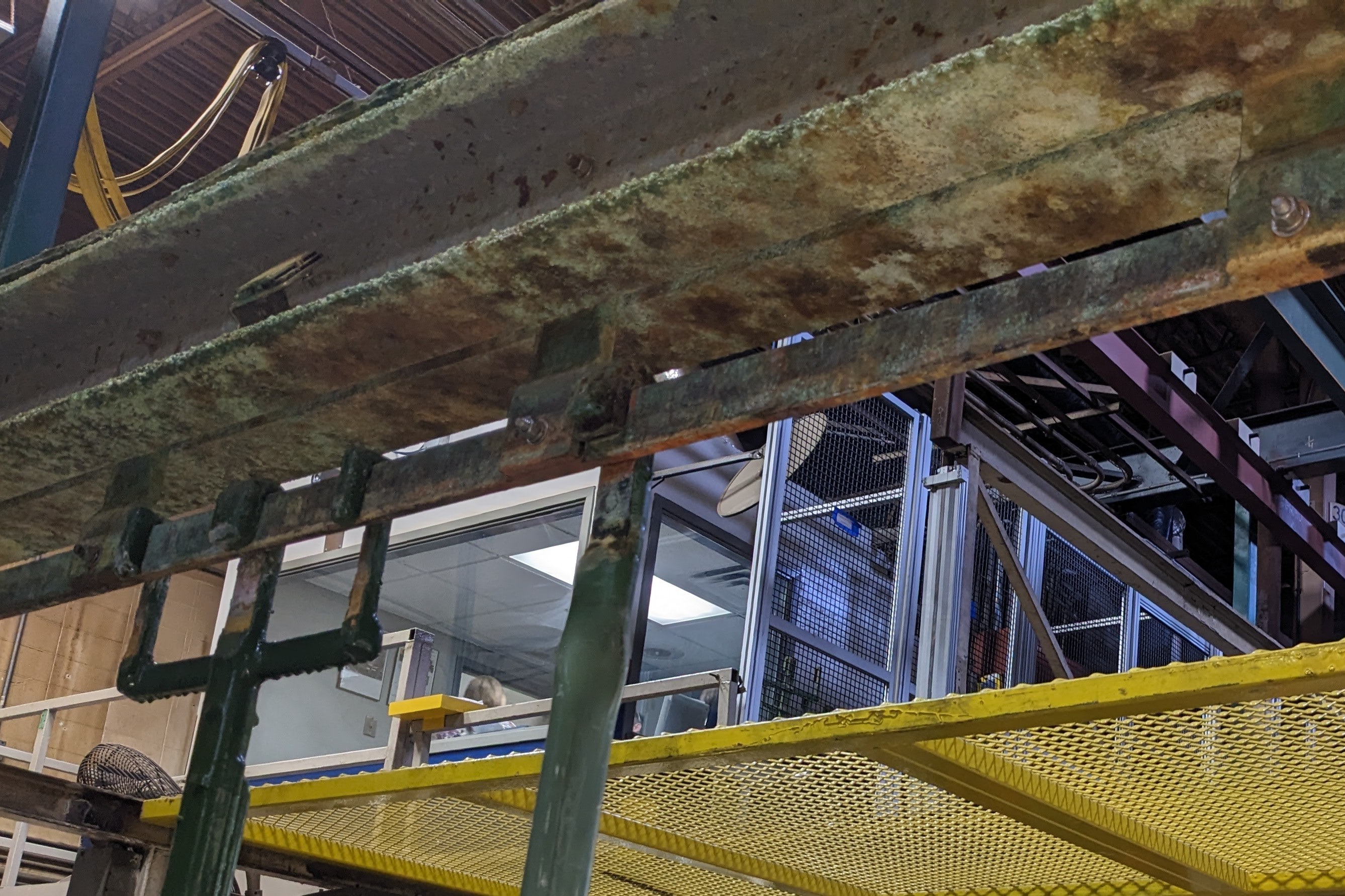
Current flow can be inhibited by unclean current carrying joints such as flight bars or rack heads because of oxidation, oils or dirt. Unclean work areas like this one should be addressed prior to plating to ensure proper plating thickness. Photo Credits: EPSI
- Low Plating Thicknesses on Parts. Some causes that can lead to insufficient current flow to a part include: not enough current supplied to the part; parts being too far from the anodes; low current density areas of the rack; or current flow being inhibited by unclean current carrying joints (such as flight bars or rack heads because of oxidation, oils or dirt). It is important to identify and address these issues to ensure proper plating thickness.
One solution to this problem is to verify that the amps/square footage of parts being run are adequate for the process. Copper mounted as close as possible
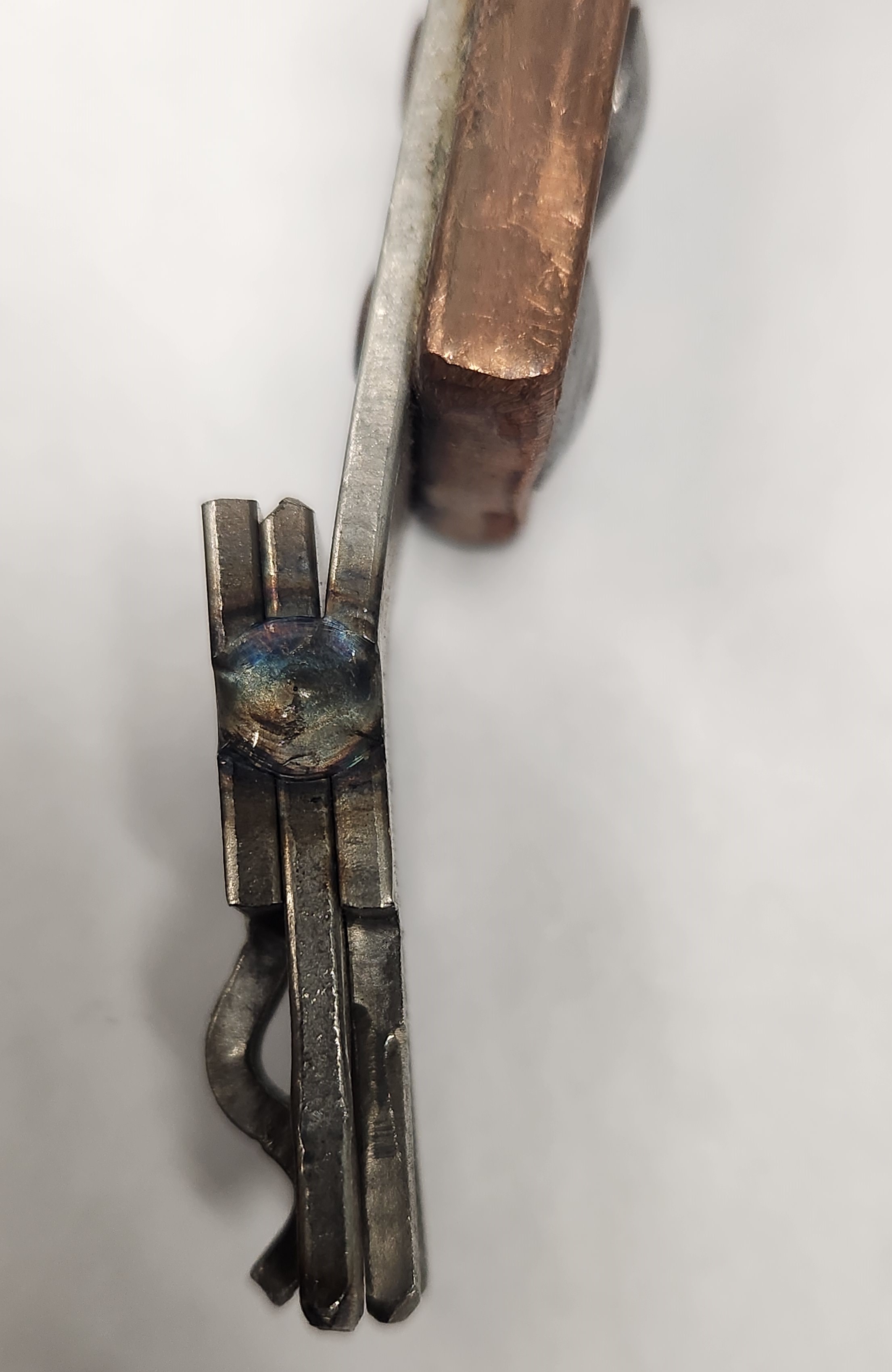
Low plating thickness can be remedied by mounting copper as close as possible to the contact, which can boost current.
to the contact can boost current. Also, it is crucial to ensure there is ample rectification to run the amperage required for the number of parts being run. As part of preventive maintenance, flight bars and rack heads should be cleaned regularly. The framework and contact material and size should also be considered to provide enough amperage to the part. The contact design is also important in order to place parts in the proper location of the tank to optimize plating. Adding auxiliary anodes to enhance plating to the part should be considered. Designing the rack to increase amperage flow to the low current density area of the rack is recommended, as well as designing contacts in the low current density area to position the parts closer to the anodes than the other parts on the rack. Last, it is a good idea to space out the parts more in the low current density area than the other parts on the rack.
- Parts Are Hard to Rack - Take Too Long to Rack - Parts Are Scratched While Loading and Unloading. There are several potential causes for these issues. Parts may have been designed without easy racking methods, which can make loading and unloading more difficult and increase the likelihood of scratches. Also, the geometries of some parts may cause them to nest together, making them more prone to damage during handling. It is also possible that the contacts were not engineered with the ergonomics of the loading and unloading process in mind, which can contribute to the problem.
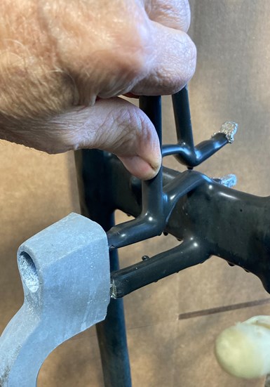
It might be beneficial to design additional components into the contact to release the part, alleviating the ergonomic strain on the loader/unloader.
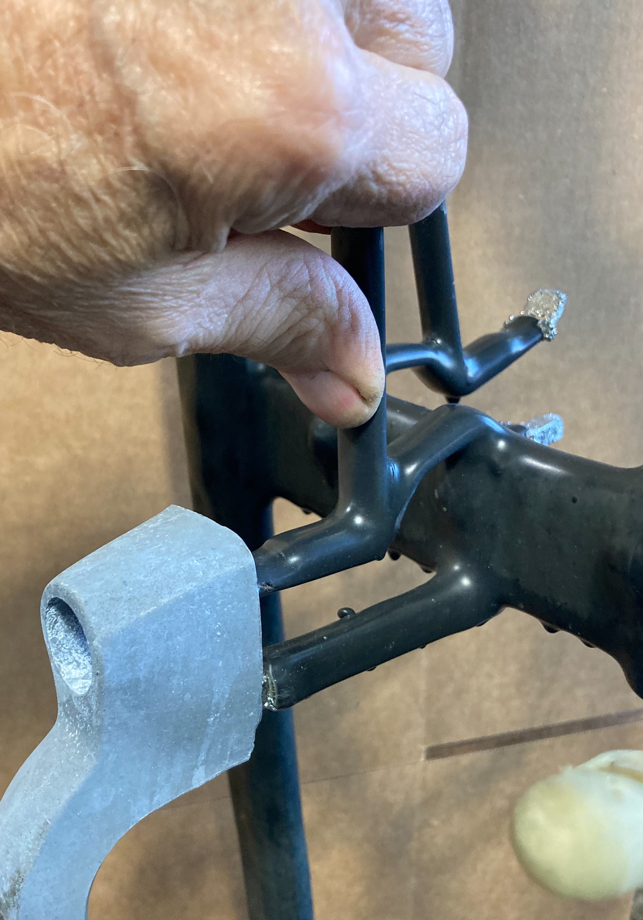
A full redesign of the rack and contacts may be a necessary solution. Creative use of part orientation to blend production needs, plating quality and ergonomic factors can also be solutions. It might be beneficial to design additional components into the contact to release the part, alleviating the ergonomic strain on the loader/unloader.
- Peeling or Cracked Plastisol Coating. One possible cause of this is an under-designed rack in terms of current-carrying capacity, which can lead to resistance and heat buildup. Another potential cause is improper application and/or curing of the plastisol coating, which can result in incomplete fusion of the coating's polymers and/or a more brittle coating. Finally, contact stress areas may be pulling against the plastisol and contributing to the problem.
Proper selection of frame and contact materials and sizes is crucial to ensure the correct current flow. It is critical to understand the application process of plastisol and apply it to coating racks, varying it depending on the materials and sizes in the rack, contact designs, and the process in which the rack will be used. If the coating application is too thin, it can cause problems; if the coating is too thick, it can also cause problems. Similarly, curing plastisol too little or too much can also lead to issues. It is essential to design contacts that stress against fasteners in the rack rather than the plastisol. It is also important to extend the spring portion of the contact away from the framework, where plastisol “webbing” can occur.
The plating process is highly intricate and requires astute attention to detail and a thorough understanding of various metals and techniques. By partnering with an experienced supplier and exercising vigilance throughout the process, you can avoid issues and achieve optimal results.
About the Authors
Kyle Faulman, Technical Racking Sales Specialist, EPSI
Doug Campbell, Senior Racking Engineer, EPSI
Bill Lloyd, Racking Design Engineer, EPSI
Sarah McKenzie, Marketing Specialist, EPSI
Contact: epsi.com
RELATED CONTENT
-
Switching from Hexavalent to Trivalent Chromium Plating
There are advantages and disadvantages of moving from hexavalent to trivalent baths. When considering this choice, gather the facts from this article in order to make a well-educated decision.
-
The Importance of Rack Maintenance
A look at how poor rack maintenance contributes to wasted time, wasted chemicals and wasted materials.
-
Anode Answers for Hard Chrome Plating
While problems continue to rise with using lead anodes for hard chrome plating, some manufacturers are discovering platinized titanium anodes as a much-improved alternative with a long list of advantages.


